Coupled Analysis of Desiccation Cracking in Unsaturated Soils through a Non-Local Mathematical Formulation

Engineering School of Sustainable Infrastructure and Environment, University of Florida, Gainesville, FL 32611, USA
*
Author to whom correspondence should be addressed.
†
These authors contributed equally to this work.
Geosciences 2019, 9(10), 428; https://doi.org/10.3390/geosciences9100428
Submission received: 9 August 2019
/
Revised: 26 September 2019
/
Accepted: 28 September 2019
/
Published: 2 October 2019
(This article belongs to the Special Issue Behavior of Expansive Soils and its Shrinkage Cracking)
Abstract
:The formation of desiccation cracks in unsaturated soils as a discontinuity phenomenon can compromise the integrity of civil infrastructure on unsaturated soils. Because of the singularity at such discontinuities, the mathematical modeling of desiccation cracking is challenging. In this study, we apply a coupled nonlocal peridynamic poroelastic framework to model desiccation cracking in unsaturated soils. The soil skeleton is modeled by a nonlocal peridynamic elastic solid. A peridynamic equivalence of the generalized Darcy’s law is utilized to model unsaturated fluid flow. Cracking is determined by a critical stretch criterion between material points as well as an energy criterion. We present numerical simulations of desiccation cracking in soil bars and thin soil discs for one-dimensional cracking and two-dimensional cracking networks, respectively. The numerical results have demonstrated that the proposed nonlocal mathematical framework is a promising and robust method for modeling desiccation cracking in unsaturated soils.
1. Introduction
Unsaturated soils are three-phase porous media, namely, the solid skeleton, pore water and pore air. Matric suction is the difference between pore air pressure and pore water pressure. Variations of matrix suction can change the effective stress state of unsaturated soils [1,2] and thus have a drastic effect on the mechanical behavior of unsaturated soils [3,4,5] as observed in the phenomenon of desiccation cracking [6,7]. Desiccation cracking is a phenomenon in which surface cracks develop in clayey soils as they shrink when dried [8,9]. The behavior of clay or clayey minerals with varying matric suction is reponsible for such swell/shrink behavior. Desiccation cracks can create natural faults in a soil mass that compromise the integrity of civil infrastructure like roads and pavements [10]. Desiccation cracks can cause an increase in the compressibility of soils and thus considerably affect soil slope stability [11,12]. Studies have shown that the hydraulic conductivity of clayey soils is impacted by desiccation and subsequent cracking [13,14]. Experimental studies indicate that the hydraulic conductivity of desiccated clay liner could be increased by order of two or three because the cracks can act as a preferential pathway for water flow and contaminant transport [15]. Deep cracks in periods of drought can allow liquid infiltration into deeper layers when the drought ends and thus compromise the stability of foundations. Given the significance of desiccation cracking in the integrity of civil infrastructure, it is of vital importance to formulate a robust mathematical framework for modeling the inception and propagation of desiccation cracks in soils. This endeavor has been hindered by the fact that unsaturated soil is a complex, multi-phase mixture whose physical attributes vary drastically with varying mositure and soil particle size [16,17,18]. It has been well recognized that geomaterials are prone to discontinuous material response such as shear bands or cracks that can be triggered by spatial heterogeneities in density [19,20] and matric suction [21] as well as changes in temperature [22]. As water escapes the pore space through evaporation, very high negative pore water pressure (suction) can develop through the formation of water menisci between soil grains [23,24]. The soil stiffness such as bulk and shear moduli as well as the fracture toughness are functions of matric suction in soils. The adhesion at the interfaces between soil grains and pore water also changes with moisture content. These factors have contributed to the lack of any rigorous analytic solution for desiccation cracking. Therefore, most research work on the subject of desiccation cracking is experimental or numerical analyses. Next, we present a comprehensive review of the experimental and numerical analyses of desiccation cracking as well as introduce the nonlocal methodology proposed in this article for modeling desiccation cracking.
Kleppe and Olson [25] conducted laboratory testings of plate-shaped specimens of various compacted clay and sand mixtures to understand their suitability as impermeable liners. Their results showed that compacted clays tend to crack on drying and the shrinkage strain linearly depends on the initial water content. While increasing the sand content of the mixture made it more resistant to crack, it could significantly increase the hydraulic conductivity of the mixture before pre-cracking. Konrad and Ayad [26] conducted a field study in which an excavation with three different levels was exposed to continuous evaporation for 35 days to observe and document the formation of shrinkage cracks in an intact and weathered sensitive marine clay. Miller et al. [6] performed a laboratory study on clayey soils from Detroit, Michigan. In their tests, soil samples were subjected to a testing cycle consisting of three distinct stages, compaction-drying, dry-wetting and wet-drying. Their experimental results showed that crack propagation was most intense for a short duration of the wet-drying stage in which only small changes in matrix suction were observed. Considerable changes of suction occurred later in the drying but had little effect on crack propagation. These results were then corroborated by the laboratory testing results by Yesiller et al. [27] and Peron et al. [28] as well as the field testing by Li and Zhang [7]. Tang et al. [29] conducted laboratory desiccation tests on initially saturated thin clay layers. Their experimental results showed that the volume shrinkage was only derived from vertical subsidence before crack initiation. After crack initiation, the vertical subsidence rate slowed down while the lateral shrinkage strain increased quickly. Most of the cracks and volume shrinkage occurred while the specimen was still saturated. The initial growth direction of new cracks was generally perpendicular to the existing cracks. Moreover, when a crack approached an existing crack, it changed direction to meet the existing cracks perpendicularly. Lu and Kaya [30] proposed a drying cake method for measurement of the suction-stress characteristic curve, soil water retention and hydraulic conductivity under drying conditions. This methodology is faster and simpler than existing methodologies. This drying cake method employed a particle image velocimetry technique to determine the radial displacement, while the moisture content of the specimen was recorded using an electronic balance.
While experimental testing can provide intuitive and phenomenological observations of desiccation cracking, the accurate measurement of parameters can be challenging and the intrinsic mechanism cannot be readily explored by an experimental test. Both theoretical analysis and numerical methods such as the finite element method and the discrete element method have been utilized to study desiccation cracking in soils. Konrad and Ayad [31] developed a simple framework based on the theory of linear elastic fracture mechanics to model the formation of desiccation crack in clayey soils. In this framework, cracks occur when the horizontal stress component is identical to the tensile stress in soils. Ayad et al. [32] validated this model by comparing the predicted and observed results of a field-scale desiccation problem. Asahina et al. [33] developed a hybrid numerical model that combines the finite volume method for multiphase subsurface flow with a rigid body spring network formulation for a lattice-based representation of elasticity and fracture. This model for desiccation cracking was validated against the experimental data of mining waste cracking by Rodriguez et al. [34]. While this model can capture numerical data like the degree of saturation and time of crack initiation, the numerical results showed a distinct over-prediction of crack width as well as a significant discrepancy between the predicted and tested crack patterns for soil samples with a larger thickness. Sanchez et al. [35] presented a numerical technique in which high aspect ratio elements are inserted into a standard finite element mesh to track the relative displacement jump between elements after crack initiation during desiccation cracking. This method can reproduce some aspects of the crack patterns, cell sizes and the dependence of these features on the thickness of the specimen for two-dimensional cases (i.e., a thin-layer specimen). Dong Vo et al. [36] developed a fully coupled, elastic-damage numerical model of desiccation cracking in clayey soils using the cohesive fracture enhancement for the finite element method. Their numerical results demonstrated that desiccation cracks could initiate from the base of the soil specimen and propagate upwards, as observed by Gui et al. [37].
The discrete element method [38] has also been applied to modeling desiccation cracking in soils. Peron et al. [39] presented a discrete element approach for modeling desiccation cracking. Amarasiri et al. [40] developed a discrete element model for modeling desiccation cracking in which the material properties such as stiffness and tensile strength of soil are expressed as approximate functions of moisture content. This model can capture some essential physical aspects of crack evolution in soil samples contained in molds with varying lengths and heights. Amarasiri and Kodikara [41] utilized the cohesive crack method to overcome limitations of numerical models based on linear elastic fracture mechanics (LEFM). The advantage of the cohesive crack method is that it can be applied in situations where no preexisting crack exists. However, the potential crack paths need to be predefined. Sima et al. [42] presented a three-dimensional discrete element approach to predict the initiation and propagation of desiccation cracks in a thin clay layer. In this model, the soil was represented by an assemblage of aggregates linked by mechanical bonds between aggregates. This model was able to qualitatively capture the primary mechanism of desiccation cracking in a thin clay layer due to stress concentration but failed to capture the hierarchical progression of cracking. Gui and Zhao [43] extended the distinct lattice spring model to simulate desiccation cracking by introducing a two-phase bond model that contains spring and water bonds. The water bond was used to represent the role of the suction during desiccation, whereas the spring bond represents the mechanical interaction between soil particles. Hirobe and Oguni [44] performed a coupled analysis of desiccation cracking by using the finite element method for desiccation (described by the diffusion equation) and the particle discretization scheme finite element method (PDS-FEM) for deformation and cracking. PDS-FEM uses a pair of conjugate geometries (Voronoi and Delaunay tessellations) to describe the displacement and strain fields. In this method, cracking is modeled as a loss of interaction between Voronoi blocks and cracks can only propagate along the boundaries between Voronoi cells. Gui et al. [37] proposed a hybrid continuum-discrete element method in which desiccation cracking is simulated by a mix-mode cohesive fracture model. Gui et al. [45] applied this method to simulate the field experimental testing reported by Konrad and Ayad [26]. Their numerical results can only reproduce the general trend of settlement observed in the experimental testing.
The formation of desiccation cracks in unsaturated soils is a discontinuity phenomenon. Because of the singularity at such discontinuities [46,47,48,49], the mathematical modeling of desiccation cracking is challenging. In this article, we formulate nonlocal poroelastic model for modeling desiccation cracking in unsaturated soils through the state-based peridynamics [50,51]. Peridynamics is a nonlocal mathemathical theory of solid mechanics that attempts to unite the mathematical modeling of continuous media, cracks and particles within a single framework [52]. Peridynamics has been applied to modeling fracture in a broad spectrum of materials including metals, fiber-reinforced composites and geomaterials. In peridynamics the governing equations are integral or integro-differential equations. Thus, peridynamics is capable of handling strong discontinuities such as cracks [53]. Ouchi et al. [54] developed poroelastic peridydnamic model to study hydraulic fracturing in reservoir engineering. They utilized a cumulative damage concept to track the broken mechanical bonds for each material point. Oterkus et al. [55] formulated a fully coupled poroelastic framework for fluid flow in fracturing porous media using bond-based peridynamics in which Poisson’s ratio is limited to one quarter. Jabakhanji and Mohtar [56] presented a bond-based peridynamic model for unsaturated fluid flow in soils. Jabakhanji [57] proposed a coupled poroelastic model for modeling cracks in unsaturated soils through bond-based peridynamics. Peridynamics has been also applied to modeling shear band or strain localization in variably saturated geomaterials [3,21] as a discontinuity problem. Song and Khalili [58] formulated and implemented a nonlocal elastoplastic constitutive model for unsaturated soils through the principle of constitutive correspondence of in the state-based peridynamics. As demonstrated by their numerical results, the thickness of the shear band could be characterized naturally by the inherent length scale in the formulation. Song and Menon [59,60] developed a perdynamic model for modeling shear band in unsaturated soils triggered by the coupled chemo-hydro-mechanical processes. Recently, the authors have formulated and implemented a fully coupled nonlocal hydromechanical framework for modeling strain localization in unsaturated soils through state-based hydromechanical peridynamics [61]. In this article, we apply this state-based peridynamic hydromechanical framework to model desiccation cracking in unsaturated soils and gain insights into the mechanisms of desiccation cracking through numerical modeling. In this framework, the soil skeleton is modeled by a nonlocal peridynamic elastic solid. Unsaturated fluid flow is modeled through a peridynamic equivalence of the generalized Darcy’s law. Cracks are determined by a critical stretch criterion between material points as well as an energy criterion. We present numerical simulations of desiccation cracking in soil bars and thin soil discs for one-dimensional cracking and two-dimensional cracking networks, respectively. The numerical results have demonstrated that the proposed nonlocal mathematical framework is a promising and robust method for modeling desiccation cracking in unsaturated soils. The proposed numerical model will be further validated by the modeling of real case studies in future research.
The remaining of this article is structured as follows. Section 2 presents the mathematical formulation of the peridynamic poroelastic model and the constitutive models for the solid skeleton and fluid flow, as well as the damage model. Section 3 presents the numerical examples of desiccation cracking in a one-dimensional bar soil sample and a two-dimensional disk soil sample, respectively, as well as the discussion of the numerical results. Section 4 summarizes the conclusions of this article. For sign convention, the compression stress is negative and pore water pressure is positive with a negative sign denoting negative pore water pressure for soils under unsaturated condition.
2. Mathematical Framework
The proposed mathematical framework for modeling unsaturated soils is an integration of the mixture theory for porous media and peridynamics for solids. In the mixture theory unsaturated soils are assumed as a three-phase mixture which consists of a solid skeleton, pore water and pore air. Peridynamics is a nonlocal reformulation of classical continuum mechanics through integral or integro-differential (in temporal domain) equations instead of partial differential equations. The state-based peridynamics can model continuum media, discrete particles as well as evolving cracks in the same mathematical framework. Peridynamics assumes that a solid body comprises discrete particles or material points. Each material point in a body interacts with other material points within a finite distance of itself. This finite distance is an internal length scale and is termed as ‘horizon’ . The mechanical interaction between any material points is named as a mechanical bond. In the proposed mathematical model, the soil skeleton is characterized by a nonlocal peridynamic elastic solid. Unsaturated fluid flow is modeled through a peridynamic equivalence of the generalized Darcy’s law. Cracks are simulated by a critical stretch criterion between solid material points as well as an energy criterion.
2.1. State-Based Peridynamic Poroelasticity
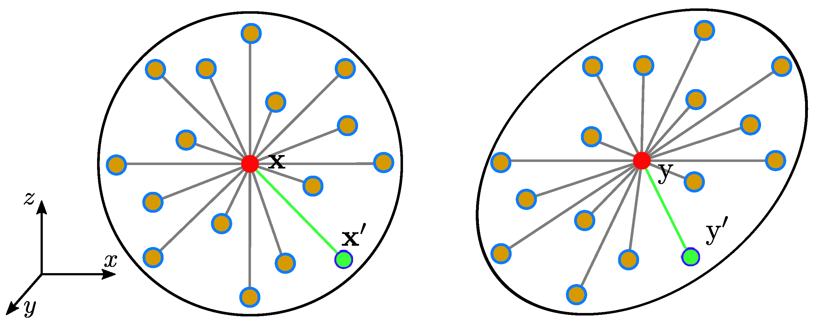
In the state-based peridynamic poroelasticity theory, unsaturated soils are assumed as a combination of solid material points and fluid material points. Assuming a passive atmospheric pressure, the air phase is not considered in the peridynamic poroelastic model. Therefore, the fluid material points are water material points. The interaction between two solid material points is called mechanical bond. Similarly, the interaction between two fluid material points is called hydraulic bond. The interaction between a solid material point and a fluid material point at a specific spatial location is described by the effective force state introduced below. The mechanical or physical response of a material point collectively depends on the deformation or physical properties (e.g., pressure head) of all material points within its horizon. For instance, the state-based peridynamics utilizes mathematical objects such as deformation state and force state to describe the constitutive behavior of solids. A deformation state is defined as a function that maps any mechanical bond onto its image under the deformation. The deformation state at any material point depends collectively on the deformation of all the bonds connected to the point. A force state contains the forces within bonds of all lengths and orientations in a material point’s horizon. Figure 1 sketches the kinematics of the material point and its neighboring material points in the framework of the state-based peridynamic poroelasticity. As shown in Figure 1, the Lagrangian coordinate system is adopted for the solid phase. The Eulerian coordinate system with respect to the initial configuration of the solid phase is utilized to describe the fluid flow in the pore space. Therefore, it is worth noting that the fluid material point overlapped on each solid material point in the current configuration of the solid-fluid mixture is different from the one overlapped on the same solid material point in the initial configuration of the mixture.
In the state-based peridynamic framework, the balance equation of linear momentum for poroelastic solids under quasi-static condition at material point in the current configuration is expressed as
where and are the total force vector states for the material points acting on the mechanical bond and the material point acting on the mechanical bond , respectively, is the volume fraction of the solid phase, is the volume fraction of the fluid phase, is the density of the solid phase, is the density of the fluid phase and is the gravity acceleration constant. The force state at the material point can be expressed through the peridynamic constitutive model as
where is the constitutive material model which builds a relationship between the deformation state and the force state. The variable represents any other internal state variables that contribute to the total force state such as fluid pressure.
The state-based peridynamic formulation of the mass balance equation of poroelastic solids at the material point in the current configuration is written as
where and are the mass flux scalar states at the material points and , respectively and and are mass source and sink terms for the fluid phase at material point , respectively. The mass flux scalar state is determined by a peridynamic approximation of the generalized Darcy’s law for unsaturated fluid flow in unsaturated that will be introduced below.
2.2. Constitutive Models
To complete the peridynamic poroelastic framework, we define two constitutive models in this part. The first constitutive model describes the relationship between the total force state and the deformation state at a material point. The second constitutive model describes the relationship between the fluid flux scalar state and the fluid potential scalar state. The reference position vector state denoted as a bond vector is defined as
where and are the reference position vectors of the material point x and its neighbor material point , respectively. The deformation vector state is defined as
where and are the position vectors of the solid material points at and in the deformed configuration, respectively. The deformation state is a fundamental kinematic quantity in peridynamics that is analogous to the deformation gradient in classical continuum mechanics.
For the special case of an ordinary state-based peridynamic material model the total force state at the material point associated with a bond is expressed as
where the term is the scalar force state that represents the magnitude of the force density in the mechanical bond , is the norm operator and the unit vector term maps this scalar force state onto the deformed mechanical bond between material points and . The scalar force state is determined through the constitutive model. For this study, we extend a peridynamic poroelastic constitutive model for saturated geomaterials [54,62] by incorporating the effective stress principle for unsaturated soils [2]. For unsaturated soils, negative fluid pressure (i.e., suction assuming passive atmospheric pressure) scaled by the degree of saturation of water is taken into account in the constitutive model by integrating it into the isotropic part of the scalar force state as follows.
where is the dilatation state (i.e., the volume change state)
is the reference scalar state defined as
is the stretch state defined as
is the influence function [51], m is the weighted volume,
is the deviator component of the stretch scalar state as
and K and G are the bulk and shear moduli, respectively. The degree of saturation can be determined by soil water characteristic curve. Here we adopt the soil water characteristic curve by van Genuchten [63] as follows.
where and are the minimum and maximum degrees of saturation, respectively, s is the matric suction, is the air-entry value of the suction and n is a fitting parameter and . For the numerical examples below, we assume kPa, , and .
For the fluid phase, the peridynamic pore fluid potential states at material points and operating on the bonds and respectively are defined as
where and are fluid pressures at the material points and in the current configuration, respectively. The mass flux scalar state at the material points and are determined by the peridynamic approximation of the generalized Darcy’s Law as follows,
where is the peridynamic micro-conductivity. The peridynamic micro-conductivity is determined by the following equation for a three-dimensional case
where is the horizon size, is the reference fluid density, is the viscosity of fluid, is the peridynamic bulk permeability. The latter is related to the classical permeability tensor [54] at the material point as
where tr is the trace operator and is the second-order identity tensor.
2.3. Damage Model
In the proposed nonlocal mathematical framework, the progressive formation of cracks is characterized by an energy-based damage model. For the bond-based formulation of peridynamic theory, Silling and Askari [64] proposed a ‘critical stretch’ failure criterion for the breakage of bonds. Cracks are initiated when the stretch of a mechanical bond between two material points and exceeds a critical value. The broken mechanical bond cannot carry any load. For the state-based peridynamics, a similar energy-based fracture criterion was proposed [65], in which a mechanical bond is broken and carries no bond-force when the strain energy density in the mechanical bond exceeds a critical value. The critical energy density in a three-dimensional case can be expressed as
where E is the fracture energy that can be obtained empirically. Both failure criteria are adopted and implemented through the influence function in the constitutive material model,
The contributions from the broken bond are neglected when summing force state over the horizon. The cumulative or progressive failure that occurs at any material point is modeled using a scalar variable called ‘damage’. The ‘damage’ variable is defined as the ratio between broken mechanical bonds and total mechanical bonds in the horizon of the material point as follows
Damage d can take any value ranging from 0 to 1. The former indicates no mechanical bond broken in the horizon. The latter indicates all mechanical bonds broken in the horizon.
3. Numerical Examples
In this part, we present two numerical examples of desiccation cracking in soils under unsaturated conditions through the proposed nonlocal mathematical framework. The first example deals with one-dimensional cracking in linearly restrained soil bar. The second example deals with two-dimensional cracking in a thin plate soil sample. For both numerical examples in this section, the matric suction (i.e., negative pore water pressure) in the soil specimen is assumed to vary uniformly. Thus, the generalized nonlocal Darcy’s law in the mathematical formulation was not used in the numerical examples presented below. In the numerical example, the interaction between the container and the soil sample is characterized by a simple short-range force model introduced by Silling and Askari [64]. The force density between material points at and is defined as
where is a critical cutoff distance beyond which the short range force vanishes and is a material constant. For the following numerical examples, we assume = 0.75 mm and = 2.5 × 10⁸ N/m6 [66].
3.1. One-Dimensional Cracking in a Linearly Restrained Soil Bar
A simple experimental test conducted to study desiccation cracking in soil is the linearly restrained drying of a soil bar. In this experimental test, an optimum wet soil slurry is poured into a long notched metallic bed in the shape of a rectangular bar and then left open to the atmosphere to dry at room temperature. As pore water evaporates, the soil undergoes volume shrinkage and the soil bar collapses on itself. However, the soil’s inward movement is retarded by the presence of the notches which create a restraint along the axis of the soil bed. Thus the soil sample desiccated under linear constraint develop parallel one-dimensional cracks as water escapes the pore space by evaporating.
Figure 2 depicts the numerical model for the linearly constrained desiccation test. The solid model has dimensions 295 mm × 12 mm × 3 mm in the Cartesian coordinate system. In the numerical model, the notched bed is reproduced by placing notches of 3 mm wide at equally spaced locations, as shown in Figure 2. The problem domain is discretized into 2744 material points with an equal volume. The horizon adopted is = 3 mm. The physical testing bed and the sides of the container are rigidly fixed. The soil bed is restricted to in-plane motion only. The contact between the testing bed and the soil sample provides a restraint on the soil sample to generate cracks. Desiccation (i.e., decrease in water saturation) is modeled as an increase in suction (i.e., negative pore pressure) in the soil sample. Because the soil sample is long and thin, it is assumed that the degree of saturation varies simultaneously in the soil sample. As the desiccation process occurs, suction in the soil sample is increased from 0 to 250 kPa over 250 equal load steps (i.e., 1 kPa per load step). The soil is assumed to deform elastically with Young’s modulus E = 50 MPa and Poisson’s ratio = 0.33.
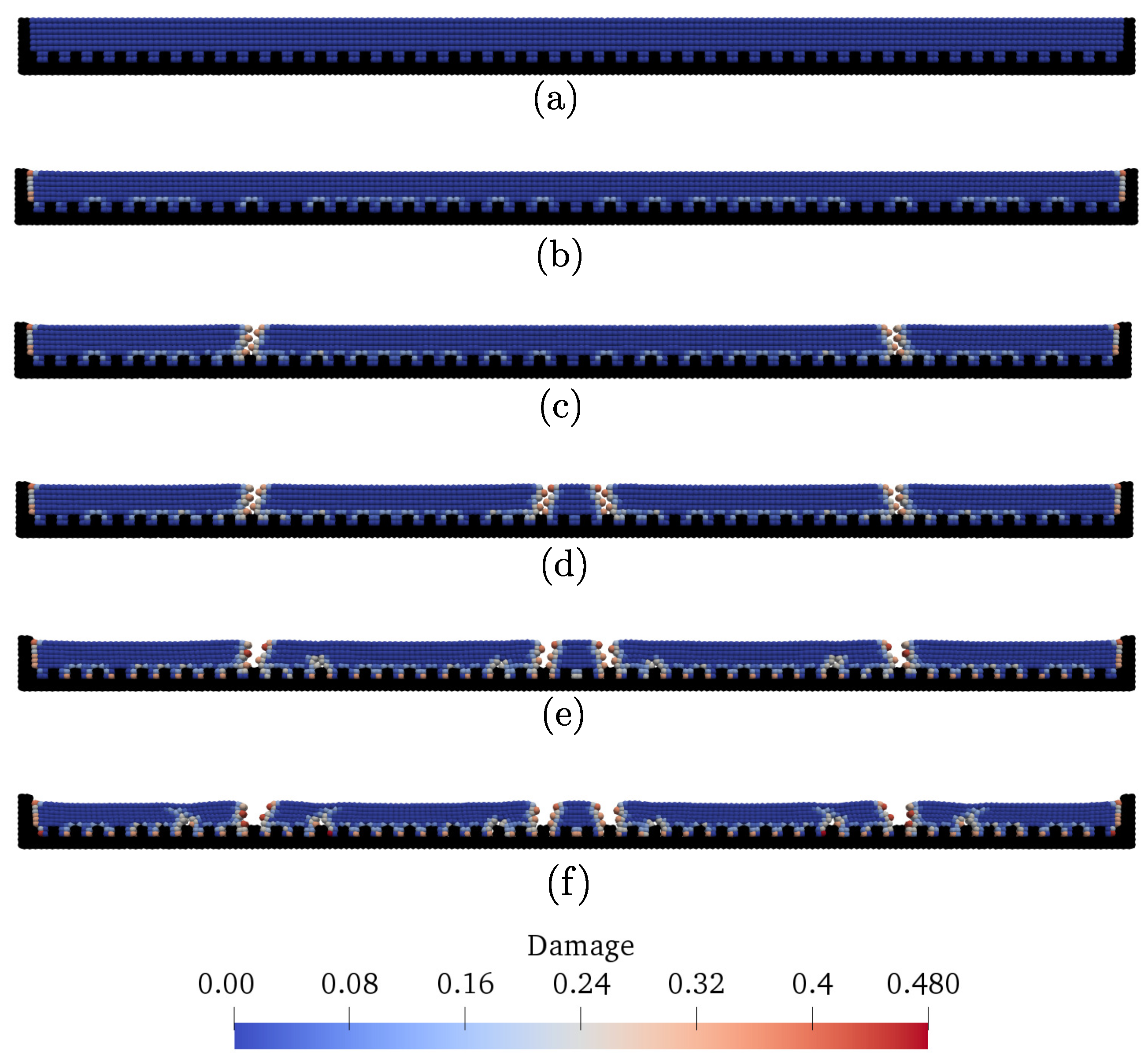
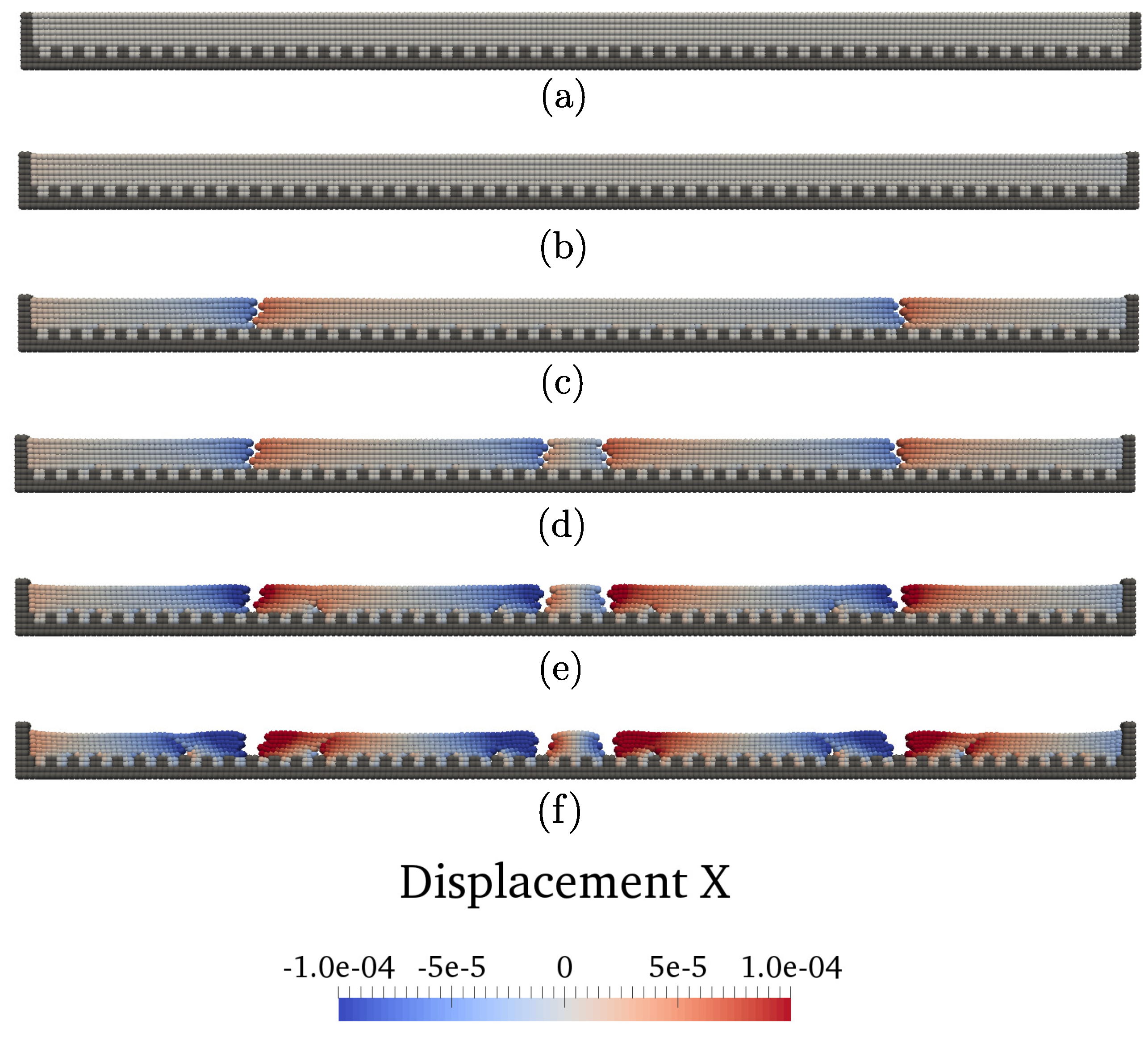
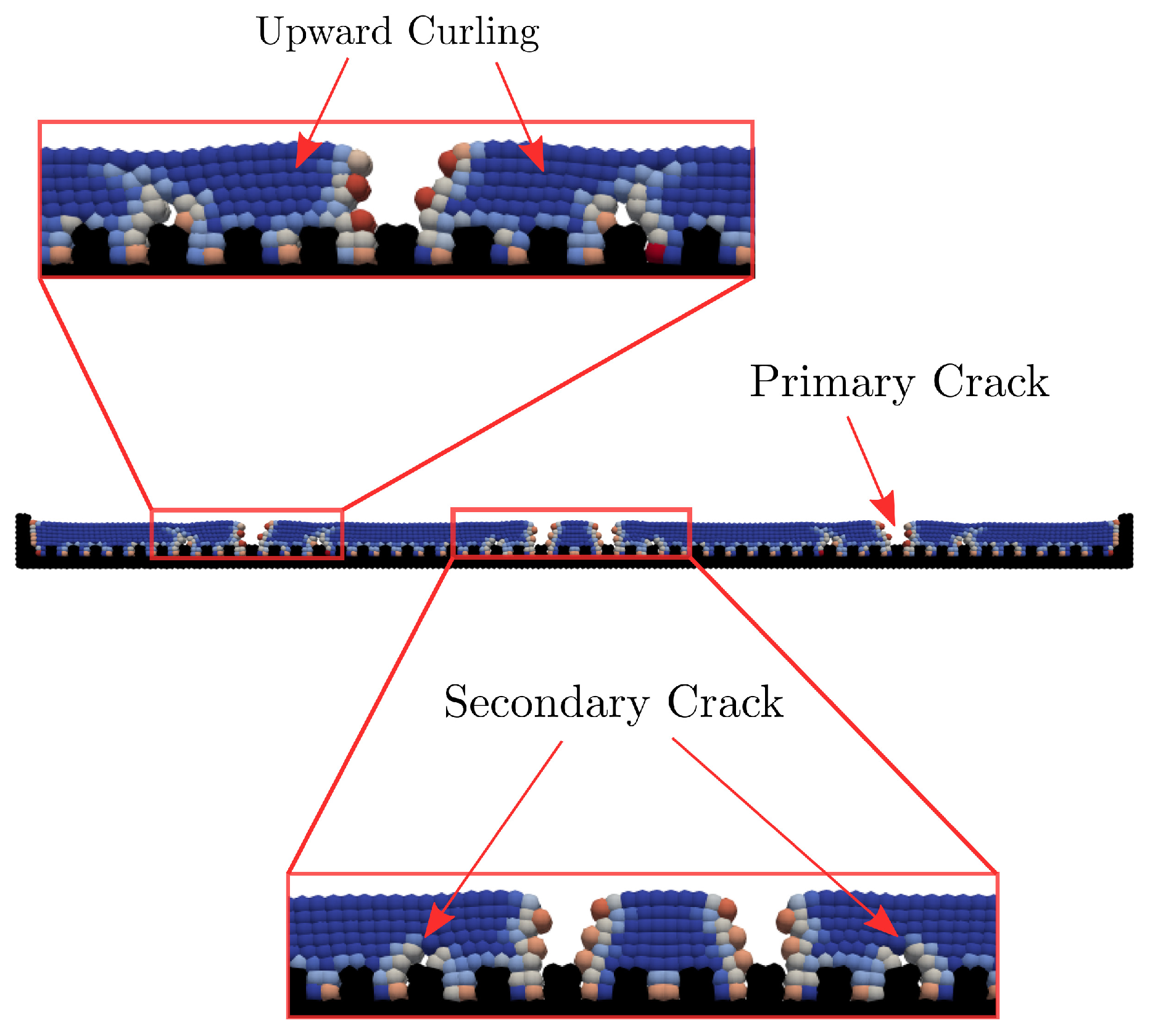
Figure 3 and Figure 4 plot the snapshots of the contours of the damage variable and the displacement superimposed on the deformed configuration at different loading stages, respectively. The deformation has been amplified by a factor of 15 for clarity in both figures. Figure 5 shows a detailed view of the final state of the soil cake with primary cracks in the domain and secondary cracks and upward curling of the soil cake caused by restrained shrinkage. The results in Figure 3 and Figure 4 demonstrate the inception and propagation of cracks in the soil sample. Figure 3b shows that there is an only settlement in the soil sample and no cracking. However, damage occurs at both ends and on the base of the soil sample. This may be explained by the fact that desiccation induced shrinkage has caused the soil to move away from the container walls. Figure 3c shows the occurrence of the first primary cracks (Mode I or opening cracks). These cracks are closer to the ends of the sample. As shown in Figure 3d two more primary cracks have formed at the load step 100, which are closer to the geometric center of the soil sample. As the simulation progresses, the primary cracks have widened as the soil continues to shrink, as shown in Figure 3e. Meanwhile, tiny secondary cracks have occurred near the primary cracks, as shown in Figure 3f. At the end of the simulation, four fully propagated primary cracks have formed with six smaller secondary cracks near the primary ones. Suction (i.e., negative pore water pressure) upon the inception of the first crack is 90 kPa. All the primary cracks occur in the suction ranging from 90–100 kPa. When suction continues to increase, no more primary cracks formed. Instead, the primary cracks became wider and smaller secondary cracks initiated near the primary ones.
All cracks observed in the final configuration are mode I cracks, which may imply that desiccation cracking occurs as a result of recursive tensile strength mobilization [28]. The results in Figure 3 and Figure 4 demonstrate that cracking may initiate at the base of the sample and then propagates upward to the top boundary. Numerical studies through other numerical methods have predicted a similar behavior of desiccation cracking in soils [36,37]. Furthermore, the primary cracks first formed in pairs at locations near the far ends of the sample. As suction continues to increase, further shrinkage caused a pair of cracks at the center of the soil sample in that the soil with cracks near the boundaries can deform freely (less constraint). At the load step 180, smaller secondary cracks open in the vicinity of the primary cracks, causing the soil to curve upwards. In summary, while the initial primary cracks propagate through the thickness rapidly, the smaller secondary cracks propagate as well as their apertures grow slowly over time. These results demonstrate that the proposed mathematical framework is capable of capturing characteristics of desiccation cracks in one-dimensional desiccation cracking tests. The laboratory testing of desiccation cracking suggests cracking initiate at the top boundary where the soil is exposed to the atmosphere and then propagates downward [28]. This discrepancy may be related to the assumption of an uniform saturation variation in the soil sample.
3.2. Two-Dimensional Cracking in a Thin Disc Soil Sample
Laboratory tests of desiccation cracking that have been widely conducted are the drying and cracking of thin disc soil samples enclosed in a testbed. Several such studies were reviewed and discussed in the introduction section of this article. In general, such experimental testing can be outlined as follows. A thin disc of wet soils in a walled container is left open to the atmosphere for drying. Over time, as pore water escapes through evaporation, significant negative pore water pressure (i.e., suction) will develop in the soil sample. The increase in suction will trigger volume shrinkage and subsequently cracking, as the soil adhesion to the container wall retards the displacement of soil grains. In this part, we conduct numerical modeling of a disc soil sample with a diameter of 118 mm and a thickness of 4 mm. As shown in Figure 6, the soil sample is in brown and the ring wall of the container is in blue. The model is discretized into 23,000 material points (e.g., Voronoi cells). The particle radius ranges from 0.5 mm to 1 mm with a median radius of 0.775 mm. The base of the plate and the wall of the container are rigidly fixed. Given that the sample thickness is negligible compared to its diameter, we assume that the matric suction (or the degree of saturation) changes uniformly in the soil sample for simplicity. Thus, the desiccation process is modeled as a uniform increase in suction with a constant rate in the soil sample. As the initial condition, the soil disc is assumed to be fully saturated. Thus the initial suction in the soil sample is zero. As the loading protocol, suction in the domain is increased from 0 to 40 MPa through 200 load steps with a rate of 0.2 MPa per load step. The elastic soil material properties are Young’s modulus E = 30 MPa and Poisson’s ratio = 0.3.
Two horizons adopted for this problem are 2.2 mm and 3.0 mm, respectively. Figure 7 plots the snapshots of the contours of the damage parameter (the fraction of broken bonds in a soil material point’s horizon) superimposed on the deformed configuration at six load steps for the simulation with = 2.2 mm. These load steps correspond to suctions of 0.5, 1, 1.5, 2, 3 and 4 MPa, respectively. The results in Figure 7 show the progressive cracking of the soil discover the simulation time. Figure 7a shows the damage caused by desiccation first occurs inside the soil sample instead of the edges. Figure 7b shows the first cracks are visible on the top surface of the disc. Figure 7c demonstrate that the cracks have propagated to the edges of the sample. The results in Figure 7d show that the crack network grows denser and are interconnected. Figure 7e,f show that the crack network has evolved with wider and deeper cracks in the sample.
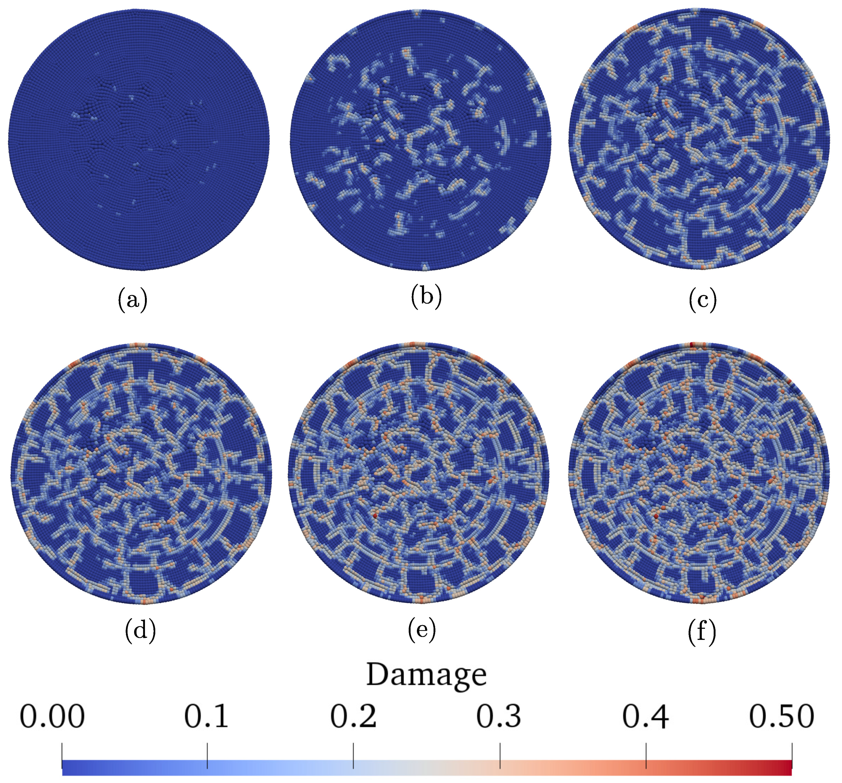
The experimental work [29] showed that the crack growth follows three distinct stages: (i) primary cracks initiate and propagate to form blocks; (ii) small secondary cracks split the blocks between primary cracks; and (iii) the cracking network stabilizes with wider crack apertures and no new crack formation. The results in Figure 7 are consistent with these three distinct stages. For instance, Figure 7c,d represent the results on stages (i) and (ii) and Figure 7e,f represent the results on stage (iii). The results in Figure 7 also demonstrate that primary cracks initiate at the load step 50 (i.e., the suction of 1 MPa) and all major cracks have formed by the loading step 75 (i.e., the suction of 1.5 MPa). Further increase in suction causes smaller branching cracks in the soil disc. The experimental work conducted by Peron et al. [28] confirmed the existence of two distinct domains of cracking. For instance, the crack network divides the problem domain into irregularly shaped polygons. Figure 7 shows that the primary cracks have a distinct tendency to join perpendicular to each other, which is supported by experimental studies [29,34]. Our numerical simulation may over-predict the number and intensity of cracking of a similar soil sample experimentally tested in Reference [29] and numerically modeled in Reference [42]. This over-prediction may be due to the fact that the matric suction is assumed to vary uniformly in the thin soil bar.
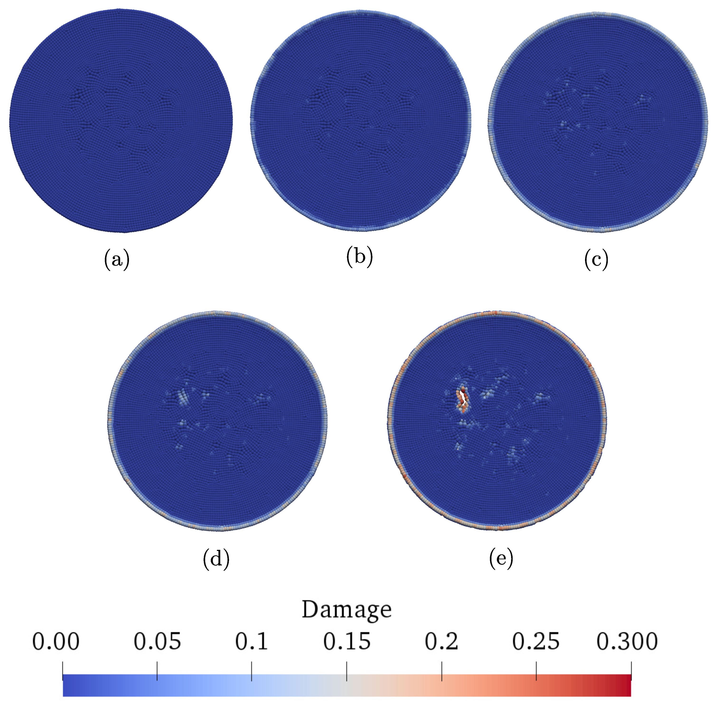
Figure 8 shows the contours of damage in the thin soil disc at five load steps simulated with the horizon of 3 mm and the same loading rate. Figure 8b shows that damage first occurs at the boundary of the soil sample where it touches the wall of the container. This damage may be triggered by the relative motion between the soil and container wall. Figure 8c,d demonstrate the inception and propagation of damage within the soil sample. Figure 8e shows the contour of the damage at the load step of 50. The results show the crack has fully developed. As shown in Figure 8, the first crack occurs randomly in the soil sample, which agrees with both numerical and experimental observations of desiccation cracking [29,42]. Comparison of results with two different horizons demonstrates that the intrinsic length scale can be perturbed to simulate the desiccation cracking observed in the laboratory experiment tests. In summary, the proposed mathematical framework can be applied to simulate the formation of desiccation cracks in soils without any add-on modification of the framework, such as the predefined propagation path of cracks.
4. Conclusions
In this study, we apply a coupled nonlocal mathematical framework to model desiccation cracking in unsaturated soils. The soil skeleton is modeled by a nonlocal peridynamic elastic solid. A peridynamic equivalence of the generalized Darcy’s law is utilized to model unsaturated fluid flow. Cracking is determined by a critical stretch between material points as well as an energy criterion. We present numerical simulations of desiccation cracking in soil bars and thin soil discs for one-dimensional cracks and two-dimensional crack networks, respectively. The numerical results have demonstrated that the proposed nonlocal mathematical framework is a promising and robust method for modeling desiccation cracking in unsaturated soils. For instance, the numerical simulations with the proposed mathematical framework can reproduce experimentally observed characteristics of desiccation cracking such as the existence of two distinct domains of cracking and the tendency of cracks to occur rapidly in a narrow range of suction. Future work will focus on elastoplastic damage with spatial variation of the degree of saturation as well as the incorporation of basic soil expansive characteristics. The numerical experiments performed in this article are a preliminary test of the proposed numerical methodology for modeling desiccation cracking. The numerical framework will be further validated by the modeling of real case studies in future research.
Author Contributions
Both authors contributed equally to this study.
Funding
This financial support of this research was provided by the US National Science Foundation under contract number CMMI-1659932.
Conflicts of Interest
The authors declare no conflict of interest.
References
- Lu, N.; Asce, M.; Likos, W.J. Suction Stress Characteristic Curve for Unsaturated Soil; American Society of Civil Engineers: Reston, VA, USA, 2006. [Google Scholar] [CrossRef]
- Lu, N.; Godt, J.W.; Wu, D.T. A closed-form equation for effective stress in unsaturated soil. Water Resour. Res. 2010, 46. [Google Scholar] [CrossRef]
- Song, X.; Borja, R.I. Mathematical framework for unsaturated flow in the finite deformation range. Int. J. Numer. Methods Eng. 2014, 97, 658–682. [Google Scholar] [CrossRef]
- Song, X. Transient bifurcation condition of partially saturated porous media at finite strain. Int. J. Numer. Anal. Methods Geomech. 2017, 41, 135–156. [Google Scholar] [CrossRef]
- Likos, W.J.; Song, X.; Xiao, M.; Cerato, A.; Lu, N. Fundamental Challenges in Unsaturated Soil Mechanics. In Geotechnical Fundamentals for Addressing New World Challenges; Springer: Berlin/Heidelberg, Germany, 2019; pp. 209–236. [Google Scholar]
- Miller, C.J.; Mi, H.; Yesiller, N. Experimental analysis of desiccation crack propagation in clay liners. J. Am. Water Resour. Assoc. 1998, 34, 677–686. [Google Scholar] [CrossRef]
- Li, J.H.; Zhang, L.M. Study of desiccation crack initiation and development at ground surface. Eng. Geol. 2011, 123, 347–358. [Google Scholar] [CrossRef]
- Puppala, A.J.; Katha, B.; Hoyos, L.R. Volumetric Shrinkage Strain Measurements in Expansive Soils Using Digital Imaging Technology; Technical Report 6; ASTM: West Conshohocken, PA, USA, 2004. [Google Scholar]
- Puppala, A.J.; Pedarla, A.; Hoyos, L.R.; Zapata, C.; Bheemasetti, T.V. A semi-empirical swell prediction model formulated from ‘clay mineralogy and unsaturated soil’ properties. Eng. Geol. 2016, 200, 114–121. [Google Scholar] [CrossRef]
- Puppala, A.J.; Manosuthkij, T.; Nazarian, S.; Hoyos, L.R. Threshold moisture content and matric suction potentials in expansive clays prior to initiation of cracking in pavements. Can. Geotech. J. 2011, 48, 519–531. [Google Scholar] [CrossRef]
- Bagge, G. Tension cracks in saturated clay cuttings. In Proceedings of the 11th International Conference on Soil Mechanics and Foundation Engineering, San Francisco, CA, USA, 12–16 August 1985; pp. 393–395. [Google Scholar]
- Silvestri, V.; Sarkis, G.; Bekkouche, N.; Soulié, M. Evapotranspiration, trees and damage to foundations in sensitive clays. Can. Geotech. Conf. 1992, 2, 533–538. [Google Scholar]
- Boynton, S.S.; Daniel, D.E. Hydraulic conductivity tests on compacted clay. J. Geotech. Eng. 1985, 111, 465–478. [Google Scholar] [CrossRef]
- Miller, C.J.; Mishra, M. Modeling of leakage through cracked clay liners - I: State of the art 1. J. Am. Water Resour. Assoc. 1989, 25, 551–556. [Google Scholar] [CrossRef]
- Albrecht, B.A.; Benson, C.H. Effect of desiccation on compacted natural clays. Geotech. Geoenviron. Eng. 2001, 127, 67–75. [Google Scholar] [CrossRef]
- Hoyos, L.R.; Arduino, P. Implicit Algorithm for Modeling Unsaturated Soil Response in Three-Invariant Stress Space. Int. J. Geomech. 2008, 8, 266–273. [Google Scholar] [CrossRef]
- Cao, J.; Jung, J.; Song, X.; Bate, B. On the soil water characteristic curves of poorly graded granular materials in aqueous polymer solutions. Acta Geotech. 2018, 13, 103–116. [Google Scholar] [CrossRef]
- Niu, W.J.; Ye, W.M.; Song, X. Unsaturated permeability of Gaomiaozi bentonite under partially free-swelling conditions. Acta Geotech. 2019, 1–30. [Google Scholar] [CrossRef]
- Borja, R.I.; Song, X.; Wu, W. Critical state plasticity. Part VII: Triggering a shear band in variably saturated porous media. Comput. Methods Appl. Mech. Eng. 2013, 261–262, 66–82. [Google Scholar] [CrossRef]
- Song, X.; Borja, R.I. Finite Deformation and Fluid Flow in Unsaturated Soils with Random Heterogeneity. Vadose Zone J. 2014, 13. [Google Scholar] [CrossRef]
- Song, X.; Wang, K.; Ye, M. Localized failure in unsaturated soils under non-isothermal conditions. Acta Geotech. 2018, 13, 73–85. [Google Scholar] [CrossRef]
- Song, X.; Wang, K.; Bate, B. A hierarchical thermo-hydro-plastic constitutive model for unsaturated soils and its numerical implementation. Int. J. Numer. Anal. Methods Geomech. 2018, 42, 1785–1805. [Google Scholar] [CrossRef]
- Song, X.; Wang, M.C.; Zhang, K. Molecular dynamics modeling of unsaturated clay-water systems at elevated temperature. In Proceedings of the 7th International Conference on Unsaturated Soils 2018 (UNSAT2018), Hong Kong, China, 3–5 August 2018. [Google Scholar]
- Song, X.; Wang, M.C. Molecular dynamics modeling of a partially saturated clay-water system at finite temperature. Int. J. Numer. Anal. Methods Geomech. 2019, 43, 2129–2146. [Google Scholar] [CrossRef]
- Kleppe, J.H.; Olson, R.E. Desiccation cracking of soil barriers. In Hydraulic Barriers in Soil and Rock; ASTM International: West Conshohocken, PA, USA, 1985. [Google Scholar]
- Konrad, J.M.; Ayad, R. Desiccation of a sensitive clay: Field experimental observations. Can. Geotech. J. 1997, 34, 929–942. [Google Scholar] [CrossRef]
- Yesiller, N.; Miller, C.; Inci, G.; Yaldo, K. Desiccation and cracking behavior of three compacted landfill liner soils. Eng. Geol. 2000, 57, 105–121. [Google Scholar] [CrossRef] [Green Version]
- Peron, H.; Laloui, L.; Hueckel, T.; Hu, L.B. Desiccation cracking of soils. Eur. J. Environ. Civ. Eng. 2009, 13, 869–888. [Google Scholar] [CrossRef]
- Tang, C.S.; Shi, B.; Liu, C.; Suo, W.B.; Gao, L. Experimental characterization of shrinkage and desiccation cracking in thin clay layer. Appl. Clay Sci. 2011, 52, 69–77. [Google Scholar] [CrossRef]
- Lu, N.; Kaya, M. A Drying Cake Method for Measuring Suction-Stress Characteristic Curve, Soil-Water-Retention Curve, and Hydraulic Conductivity Function A Drying Cake Method for Measuring Suction-Stress Characteristic Curve, Soil-Water-Retention Curve, and Hydraulic Conductivity Function. Geotech. Test. J. 2013, 36, 1–19. [Google Scholar] [CrossRef]
- Konrad, J.M.; Ayad, R. An idealized framework for the analysis of cohesive soils undergoing desiccation. Can. Geotech. J. 1997, 34, 477–488. [Google Scholar] [CrossRef]
- Ayad, R.; Konrad, J.M.; Soulié, M. Desiccation of a sensitive clay: Application of the model CRACK. Can. Geotech. J. 1997, 34, 943–951. [Google Scholar] [CrossRef]
- Asahina, D.; Houseworth, J.; Birkholzer, J.; Rutqvist, J.; Bolander, J. Hydro-mechanical model for wetting/drying and fracture development in geomaterials. Comput. Geosci. 2014, 65, 13–23. [Google Scholar] [CrossRef] [Green Version]
- Rodríguez, R.; Sánchez, M.; Ledesma, A.; Lloret, A. Experimental and numerical analysis of desiccation of a mining waste. Can. Geotech. J. 2007, 44, 644–658. [Google Scholar] [CrossRef]
- Sánchez, M.; Manzoli, O.L.; Guimarães, L.J. Modeling 3-D desiccation soil crack networks using a mesh fragmentation technique. Comput. Geotech. 2014, 62, 27–39. [Google Scholar] [CrossRef]
- Vo, T.D.; Pouya, A.; Hemmati, S.; Tang, A.M. Numerical modelling of desiccation cracking of clayey soil using a cohesive fracture method. Comput. Geotech. 2017, 85, 15–27. [Google Scholar] [CrossRef]
- Gui, Y.; Zhao, Z.; Kodikara, J.; Bui, H.H.; Yang, S. Numerical modelling of laboratory soil desiccation cracking using UDEC with a mix-mode cohesive fracture model. Eng. Geol. 2016, 202, 14–23. [Google Scholar] [CrossRef]
- Cundall, P.A.; Strack, O.D. A discrete numerical model for granular assemblies. Geotechnique 1979, 29, 47–65. [Google Scholar] [CrossRef]
- Peron, H.; Delenne, J.; Laloui, L.; El Youssoufi, M. Discrete element modelling of drying shrinkage and cracking of soils. Comput. Geotech. 2009, 36, 61–69. [Google Scholar] [CrossRef]
- Amarasiri, A.L.; Kodikara, J.K.; Costa, S. Numerical modelling of desiccation cracking. Int. J. Numer. Anal. Methods Geomech. 2011, 35, 82–96. [Google Scholar] [CrossRef]
- Amarasiri, A.L.; Kodikara, J.K. Numerical Modeling of Desiccation Cracking Using the Cohesive Crack Method. Int. J. Geomech. 2013, 13, 213–221. [Google Scholar] [CrossRef]
- Sima, J.; Jiang, M.; Zhou, C. Numerical simulation of desiccation cracking in a thin clay layer using 3D discrete element modeling. Comput. Geotech. 2014, 56, 168–180. [Google Scholar] [CrossRef]
- Gui, Y.; Zhao, G.F. Modelling of laboratory soil desiccation cracking using DLSM with a two-phase bond model. Comput. Geotech. 2015, 69, 578–587. [Google Scholar] [CrossRef]
- Hirobe, S.; Oguni, K. Coupling analysis of pattern formation in desiccation cracks. Comput. Methods Appl. Mech. Eng. 2016, 307, 470–488. [Google Scholar] [CrossRef]
- Gui, Y.L.; Hu, W.; Zhao, Z.Y.; Zhu, X. Numerical modelling of a field soil desiccation test using a cohesive fracture model with Voronoi tessellations. Acta Geotech. 2018, 13, 87–102. [Google Scholar] [CrossRef]
- Schrefler, B.; Zhang, H.; Sanavia, L. Interaction between different internal length scales in strain localization analysis of fully and partially saturated porous media—The 1-D case. Int. J. Numer. Anal. Methods Geomech. 2006, 30, 45–70. [Google Scholar] [CrossRef]
- Lazari, M.; Sanavia, L.; Schrefler, B. Local and non-local elasto-viscoplasticity in strain localization analysis of multiphase geomaterials. Int. J. Numer. Anal. Methods Geomech. 2015, 39, 1570–1592. [Google Scholar] [CrossRef]
- Oka, F.; Shahbodagh, B.; Kimoto, S. A computational model for dynamic strain localization in unsaturated elasto-viscoplastic soils. Int. J. Numer. Anal. Methods Geomech. 2019, 43, 138–165. [Google Scholar] [CrossRef]
- Hu, L.B.; Péron, H.; Hueckel, T.; Laloui, L. Desiccation shrinkage of non-clayey soils: Multiphysics mechanisms and a microstructural model. Int. J. Numer. Anal. Methods Geomech. 2013, 37, 1761–1781. [Google Scholar] [CrossRef]
- Silling, S. Reformulation of elasticity theory for discontinuities and long-range forces. J. Mech. Phys. Solids 2000, 48, 175–209. [Google Scholar] [CrossRef] [Green Version]
- Silling, S.A.; Epton, M.; Weckner, O.; Xu, J.; Askari, E. Peridynamic states and constitutive modeling. J. Elast. 2007, 88, 151–184. [Google Scholar] [CrossRef]
- Silling, S.A.; Lehoucq, R. Peridynamic theory of solid mechanics. Adv. Appl. Mech. 2010, 44, 73–168. [Google Scholar]
- Silling, S. Dynamic fracture modeling with a meshfree peridynamic code. In Computational Fluid and Solid Mechanics 2003; Elsevier: Amsterdam, The Netherlands, 2003; pp. 641–644. [Google Scholar]
- Ouchi, H.; Katiyar, A.; York, J.; Foster, J.T.; Sharma, M.M. A fully coupled porous flow and geomechanics model for fluid driven cracks: A peridynamics approach. Comput. Mech. 2015, 55, 561–576. [Google Scholar] [CrossRef]
- Oterkus, S.; Madenci, E.; Oterkus, E. Fully coupled poroelastic peridynamic formulation for fluid-filled fractures. Eng. Geol. 2017, 225, 19–28. [Google Scholar] [CrossRef] [Green Version]
- Jabakhanji, R.; Mohtar, R.H. A peridynamic model of flow in porous media. Adv. Water Resour. 2015, 78, 22–35. [Google Scholar] [CrossRef]
- Jabakhanji, R. Peridynamic Modeling of Coupled Mechanical Deformations and Transient Flow in Unsaturated Soils. Ph.D. Thesis, Purdue University, West Lafayette, India, 2013. [Google Scholar]
- Song, X.; Khalili, N. A peridynamics model for strain localization analysis of geomaterials. Int. J. Numer. Anal. Methods Geomech. 2019, 43, 77–96. [Google Scholar] [CrossRef]
- Song, X.; Menon, S. Modeling of chemo-hydromechanical behavior of unsaturated porous media: A nonlocal approach based on integral equations. Acta Geotech. 2018, 14, 1–21. [Google Scholar] [CrossRef]
- Song, X.; Menon, S. Modeling strain localization of unsaturated porous media with chemical effect through a novel non-local method. In Proceedings of the ISSMGE TC105 International Symposium IS-Atlanta 2018 on Geo-Mechanics from Micro to Macro in Research and Practice, Atlanta, GA, USA, 10–12 September 2018. [Google Scholar]
- Menon, S.; Song, X. A fully coupled state-based peri-hydromechanical model for geomaterials. In Proceedings of the First International Symposium on Computational & Geoenvironemental Geomechanics for Underground and Subsurface Structures, Nancy, France, 12–14 February 2019. [Google Scholar]
- Turner, D.Z. A non-local model for fluid-structure interaction with applications in hydraulic fracturing. Int. J. Comput. Methods Eng. Sci. Mech. 2013, 14, 391–400. [Google Scholar] [CrossRef]
- Van Genuchten, M.T. A closed-form equation for predicting the hydraulic conductivity of unsaturated soils 1. Soil Sci. Soc. Am. J. 1980, 44, 892–898. [Google Scholar] [CrossRef]
- Silling, S.A.; Askari, E. A meshfree method based on the peridynamic model of solid mechanics. Comput. Struct. 2005, 83, 1526–1535. [Google Scholar] [CrossRef]
- Foster, J.T.; Silling, S.A.; Chen, W. An energy based failure criterion for use with peridynamic states. Int. J. Multiscale Comput. Eng. 2011, 9, 675–688. [Google Scholar] [CrossRef]
- Silling, S.; Demmie, P.; Cole, R.; Taylor, P. EMU User’s Manual; Sandia National Laboratories: Albuquerque, NM, USA, 2006. [Google Scholar]
Figure 1.
Kinematics of peridynamic poroelastic framework of a material point and its neighboring material points: (left) the initial configuration and (right) the current configuration of the solid-fluid mixture. The red dots represent solid material points and the blue circles represent water material points.

Figure 2.
Numerical model that mimics the experimental desiccation test of soil. Note: the notches are in red.
Figure 2.
Numerical model that mimics the experimental desiccation test of soil. Note: the notches are in red.

Figure 3.
Snapshots of contours of the damage variable superimposed on the deformed configuration at 6 load steps: (a) Step 1; (b) Step 50; (c) Step 90; (d) Step 100; (e) Step 180; (f) Step 250. Note: The deformation is amplified by a factor of 15 to highlight the formation of cracks.
Figure 3.
Snapshots of contours of the damage variable superimposed on the deformed configuration at 6 load steps: (a) Step 1; (b) Step 50; (c) Step 90; (d) Step 100; (e) Step 180; (f) Step 250. Note: The deformation is amplified by a factor of 15 to highlight the formation of cracks.

Figure 4.
Snapshots of contours of displacement superimposed on the deformed configuration at 6 load steps: (a) Step 1; (b) Step 50; (c) Step 90; (d) Step 100; (e) Step 180; (f) Step 250. Note: The deformation is amplified by a factor of 15 to highlight the formation of cracks.
Figure 4.
Snapshots of contours of displacement superimposed on the deformed configuration at 6 load steps: (a) Step 1; (b) Step 50; (c) Step 90; (d) Step 100; (e) Step 180; (f) Step 250. Note: The deformation is amplified by a factor of 15 to highlight the formation of cracks.

Figure 5.
Zoom-in view of the cracks. Note: The deformation is amplified by a factor of 20 for clarity.
Figure 5.
Zoom-in view of the cracks. Note: The deformation is amplified by a factor of 20 for clarity.

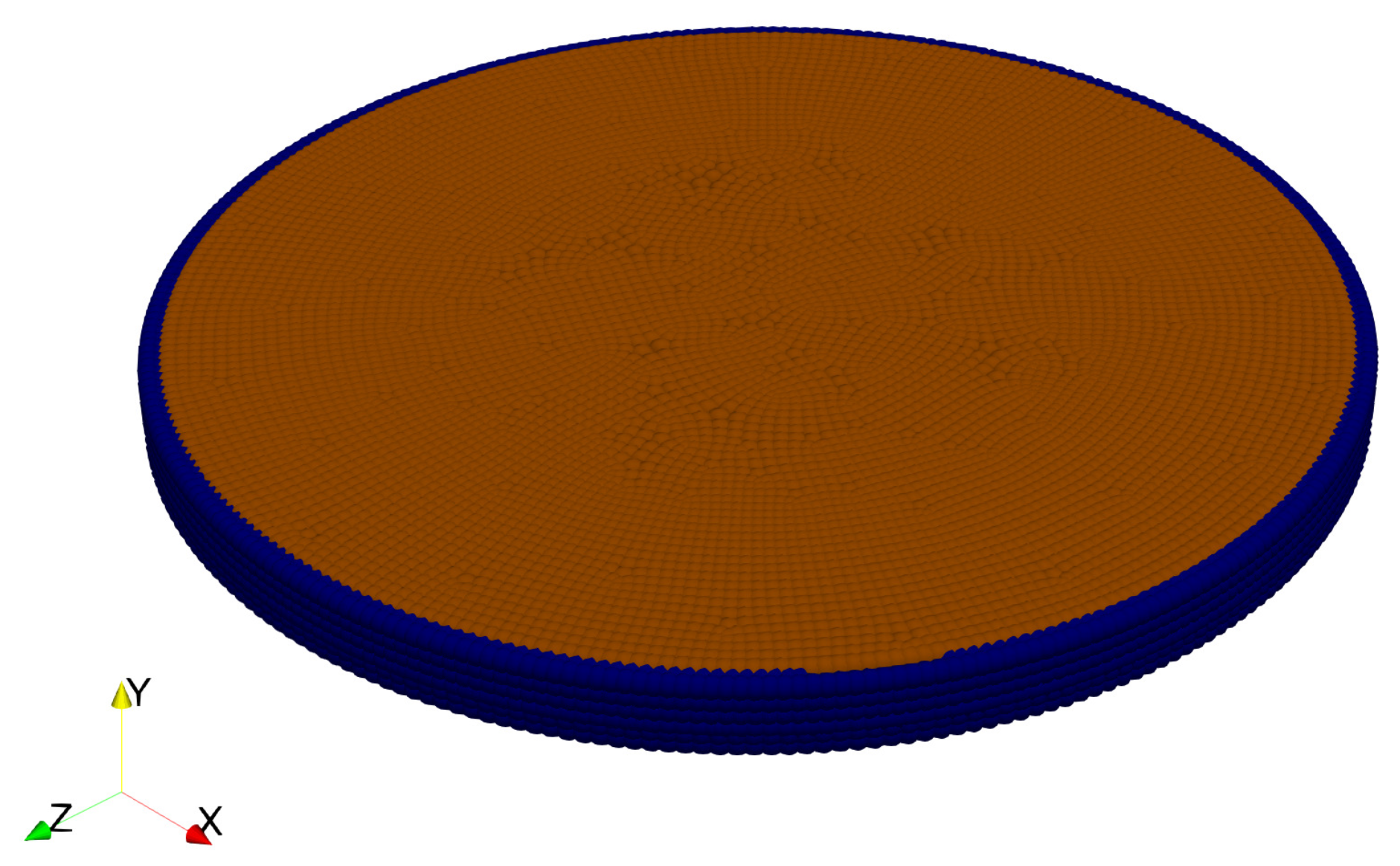
Figure 6.
Disc soil model for two-dimensional desiccation cracking simulation.

Figure 7.
Snapshots of the contours of damage in the soil sample at 6 load steps (a) Step 25; (b) Step 50; (c) Step 75; (d) Step 100; (e) Step 150; (f) Step 200, for = 2.2 mm. Note: The deformation is amplified by a factor of 5 for clarity.
Figure 7.
Snapshots of the contours of damage in the soil sample at 6 load steps (a) Step 25; (b) Step 50; (c) Step 75; (d) Step 100; (e) Step 150; (f) Step 200, for = 2.2 mm. Note: The deformation is amplified by a factor of 5 for clarity.

Figure 8.
Snapshots of the contours of damage in the soil sample at 5 load steps: (a) Step 1; (b) Step 20; (c) Step 30; (d) Step 40; (e) Step 50, for = 3 mm. Note: The deformation is amplified by a factor of 20 for clarity.
Figure 8.
Snapshots of the contours of damage in the soil sample at 5 load steps: (a) Step 1; (b) Step 20; (c) Step 30; (d) Step 40; (e) Step 50, for = 3 mm. Note: The deformation is amplified by a factor of 20 for clarity.

© 2019 by the authors. Licensee MDPI, Basel, Switzerland. This article is an open access article distributed under the terms and conditions of the Creative Commons Attribution (CC BY) license (http://creativecommons.org/licenses/by/4.0/).
Share and Cite
MDPI and ACS Style
Menon, S.; Song, X. Coupled Analysis of Desiccation Cracking in Unsaturated Soils through a Non-Local Mathematical Formulation. Geosciences 2019, 9, 428. https://doi.org/10.3390/geosciences9100428
AMA Style
Menon S, Song X. Coupled Analysis of Desiccation Cracking in Unsaturated Soils through a Non-Local Mathematical Formulation. Geosciences. 2019; 9(10):428. https://doi.org/10.3390/geosciences9100428
Chicago/Turabian StyleMenon, Shashank, and Xiaoyu Song. 2019. "Coupled Analysis of Desiccation Cracking in Unsaturated Soils through a Non-Local Mathematical Formulation" Geosciences 9, no. 10: 428. https://doi.org/10.3390/geosciences9100428
Note that from the first issue of 2016, this journal uses article numbers instead of page numbers. See further details here.