Fully Digital Workflow for Planning Static Guided Implant Surgery: A Prospective Accuracy Study

Abstract
:1. Introduction
2. Materials and Methods
2.1. Patient Enrolment
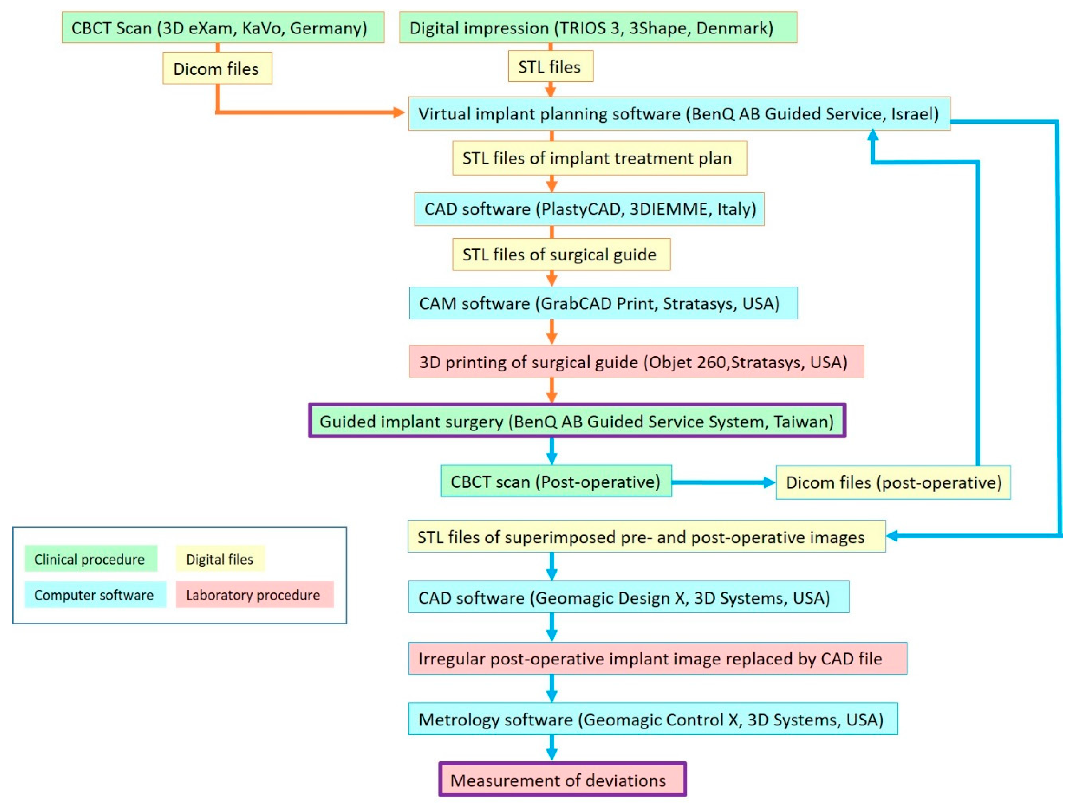
2.2. Alignment of CBCT Scan and Intraoral Scan
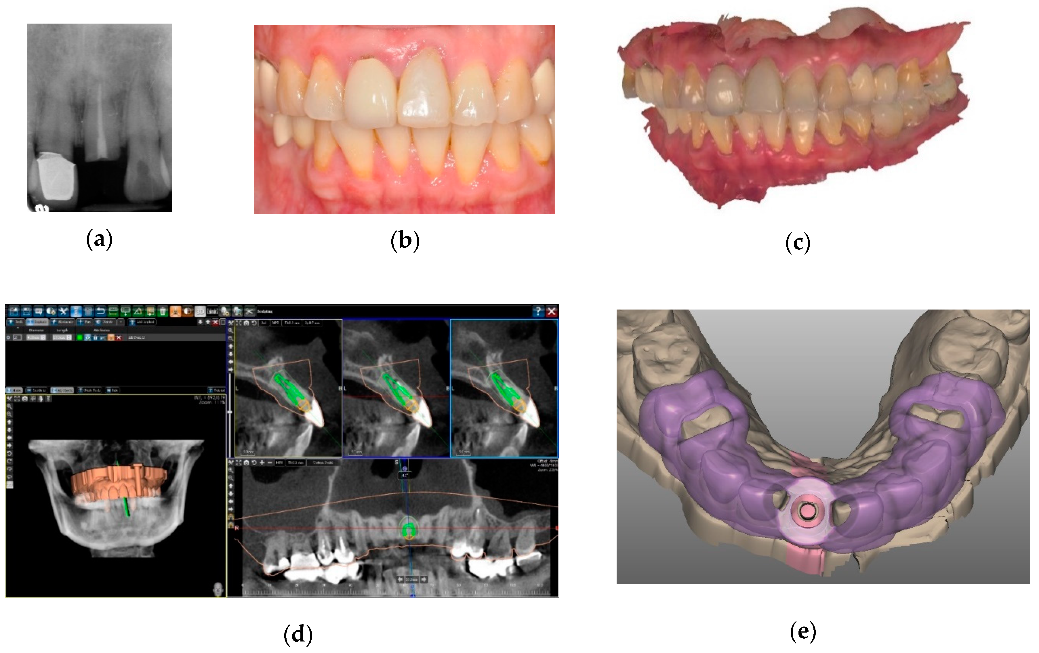
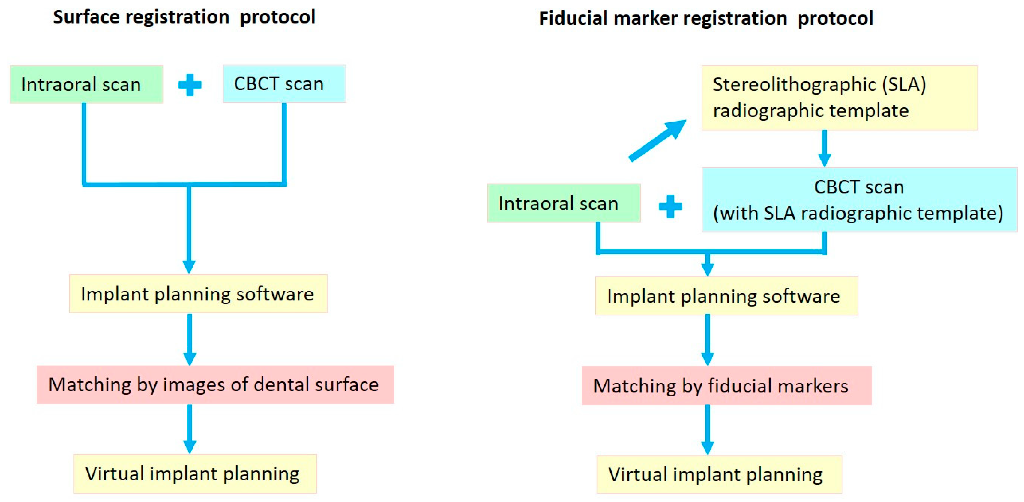
2.2.1. Surface Registration Protocol
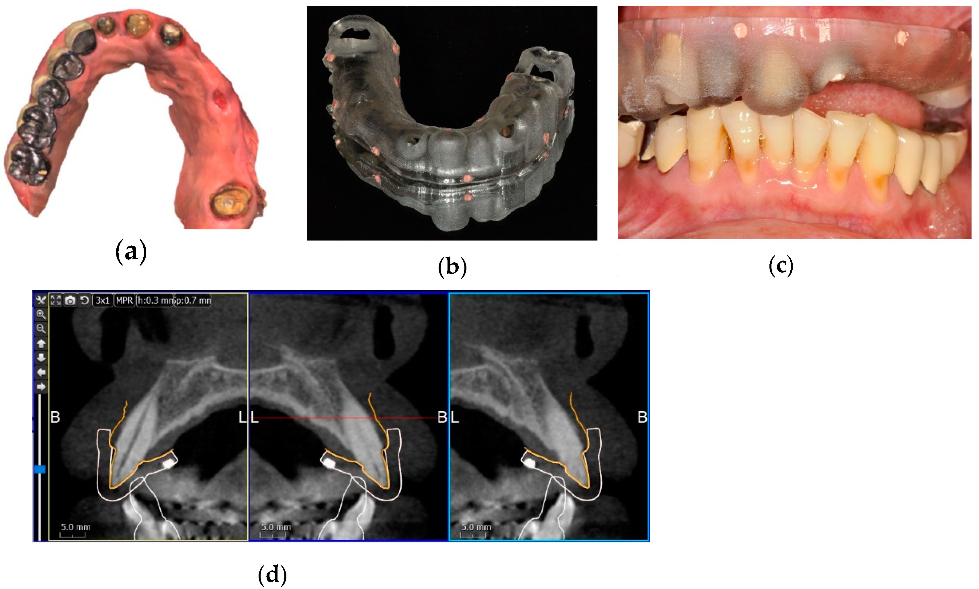
2.2.2. Fiducial Marker Registration Protocol
2.3. Implant Planning and Surgical Guide Fabrication
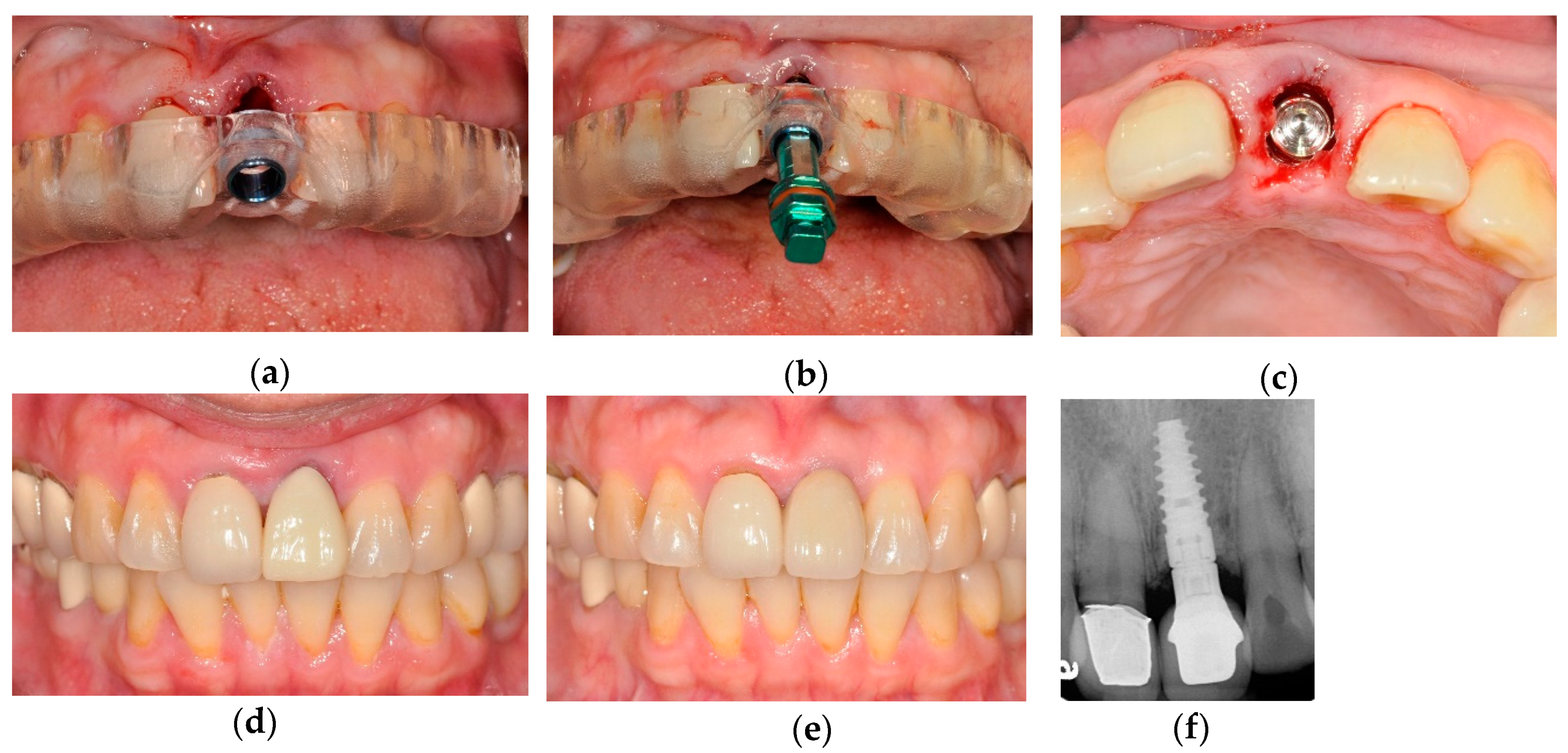
2.4. Surgical Procedure
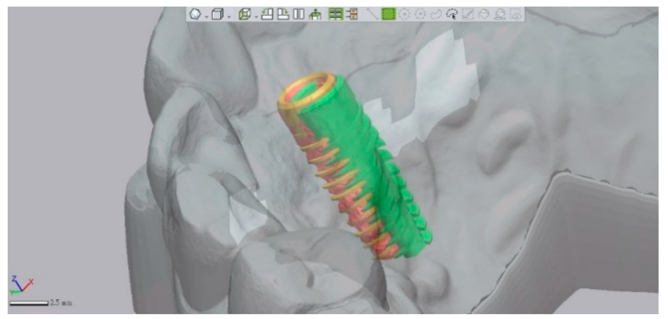
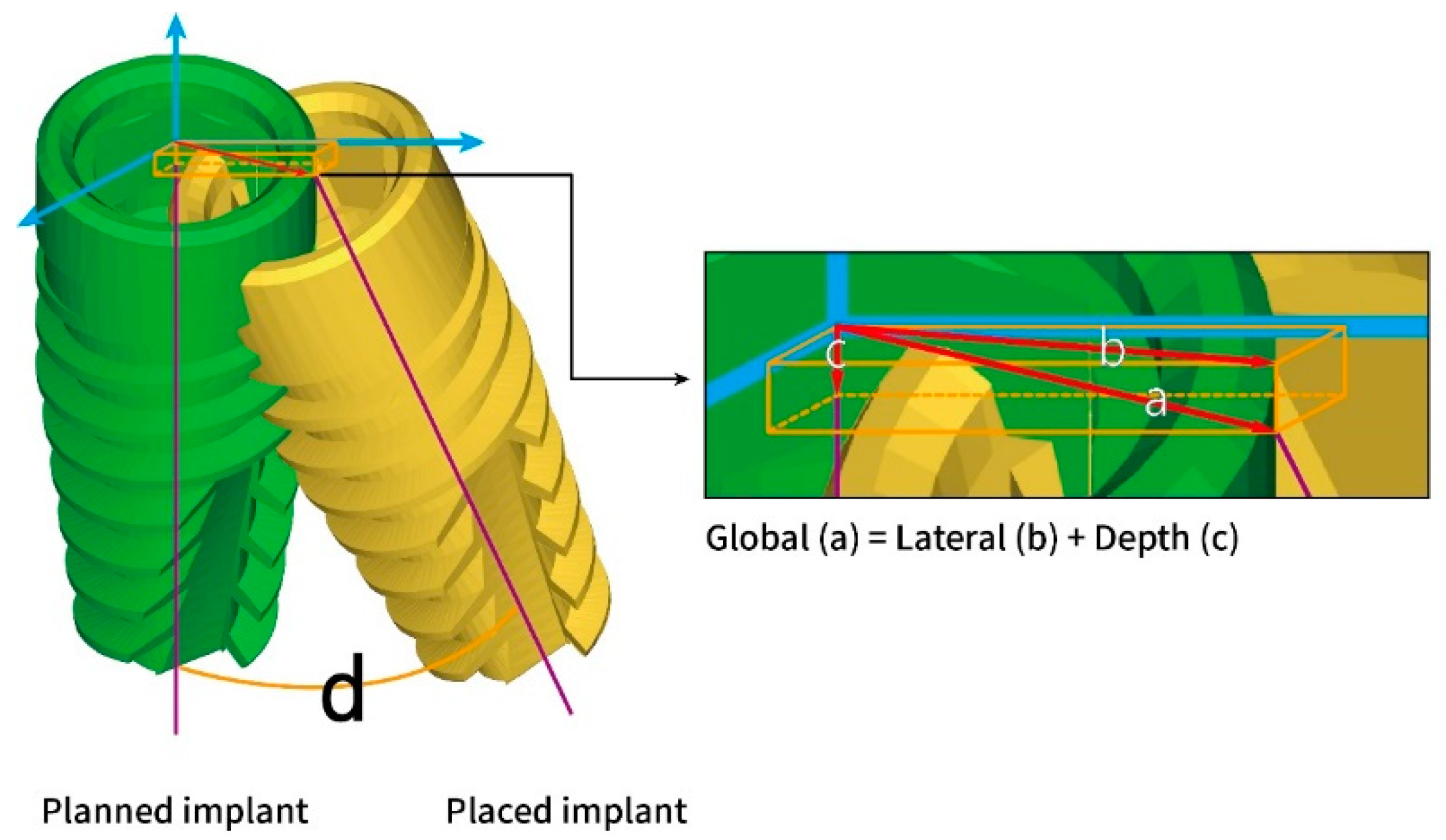
2.5. Deviation Measurement
2.6. Statistical Analysis
3. Results
4. Discussion
5. Conclusions
Author Contributions
Funding
Acknowledgments
Conflicts of Interest
References
- D’Haese, J.; Ackhurst, J.; Wismeijer, D.; De Bruyn, H.; Tahmaseb, A. Current state of the art of computer-guided implant surgery. Periodontol. 2000 2017, 73, 121–133. [Google Scholar] [CrossRef]
- Vercruyssen, M.; Laleman, I.; Jacobs, R.; Quirynen, M. Computer-supported implant planning and guided surgery: A narrative review. Clin. Oral Implant. Res. 2015, 26 (Suppl. S11), 69–76. [Google Scholar] [CrossRef] [PubMed]
- Pyo, S.W.; Lim, Y.J.; Koo, K.T.; Lee, J. Methods Used to Assess the 3D Accuracy of Dental Implant Positions in Computer-Guided Implant Placement: A Review. J. Clin. Med. 2019, 8, 54. [Google Scholar] [CrossRef] [PubMed] [Green Version]
- Vercruyssen, M.; Fortin, T.; Widmann, G.; Jacobs, R.; Quirynen, M. Different techniques of static/dynamic guided implant surgery: Modalities and indications. Periodontol. 2000 2014, 66, 214–227. [Google Scholar] [CrossRef] [PubMed]
- Vercruyssen, M.; Hultin, M.; Van Assche, N.; Svensson, K.; Naert, I.; Quirynen, M. Guided surgery: Accuracy and efficacy. Periodontol. 2000 2014, 66, 228–246. [Google Scholar] [CrossRef]
- Widmann, G.; Berggren, J.P.; Fischer, B.; Pichler-Dennhardt, A.R.; Schullian, P.; Bale, R.; Puelacher, W. Accuracy of Image-Fusion Stereolithographic Guides: Mapping CT Data with Three-Dimensional Optical Surface Scanning. Clin. Implant Dent Relat. Res. 2015, 17 (Suppl. S2), e736–e744. [Google Scholar] [CrossRef]
- Dada, K.; Pariente, L.; Daas, M. Strategic extraction protocol: Use of an image-fusion stereolithographic guide for immediate implant placement. J. Prosthet. Dent. 2016, 116, 652–656. [Google Scholar] [CrossRef]
- De Vico, G.; Ferraris, F.; Arcuri, L.; Guzzo, F.; Spinelli, D. A novel workflow for computer guided implant surgery matching digital dental casts and CBCT scan. Oral Implantol. (Rome) 2016, 9, 33–48. [Google Scholar] [CrossRef]
- Dolcini, G.A.; Colombo, M.; Mangano, C. From Guided Surgery to Final Prosthesis with a Fully Digital Procedure: A Prospective Clinical Study on 15 Partially Edentulous Patients. Int. J. Dent. 2016, 2016, 7358423. [Google Scholar] [CrossRef] [Green Version]
- Stapleton, B.M.; Lin, W.S.; Ntounis, A.; Harris, B.T.; Morton, D. Application of digital diagnostic impression, virtual planning, and computer-guided implant surgery for a CAD/CAM-fabricated, implant-supported fixed dental prosthesis: A clinical report. J. Prosthet. Dent. 2014, 112, 402–408. [Google Scholar] [CrossRef]
- Lanis, A.; Alvarez Del Canto, O. The combination of digital surface scanners and cone beam computed tomography technology for guided implant surgery using 3Shape implant studio software: A case history report. Int. J. Prosthodont. 2015, 28, 169–178. [Google Scholar] [CrossRef] [PubMed]
- Joda, T.; Gallucci, G.O. The virtual patient in dental medicine. Clin. Oral Implant. Res. 2015, 26, 725–726. [Google Scholar] [CrossRef] [PubMed]
- Arunyanak, S.P.; Harris, B.T.; Grant, G.T.; Morton, D.; Lin, W.S. Digital approach to planning computer-guided surgery and immediate provisionalization in a partially edentulous patient. J. Prosthet. Dent. 2016, 116, 8–14. [Google Scholar] [CrossRef] [PubMed]
- Jamjoom, F.Z.; Kim, D.G.; McGlumphy, E.A.; Lee, D.J.; Yilmaz, B. Positional accuracy of a prosthetic treatment plan incorporated into a cone-beam computed tomography scan using surface scan registration. J. Prosthet. Dent. 2018. [Google Scholar] [CrossRef] [PubMed]
- Pagano, S.; Moretti, M.; Marsili, R.; Ricci, A.; Barraco, G.; Cianetti, S. Evaluation of the Accuracy of Four Digital Methods by Linear and Volumetric Analysis of Dental Impressions. Materials (Basel) 2019, 12, 1958. [Google Scholar] [CrossRef] [Green Version]
- Marliere, D.A.A.; Demetrio, M.S.; Picinini, L.S.; De Oliveira, R.G.; Chaves Netto, H.D.M. Accuracy of computer-guided surgery for dental implant placement in fully edentulous patients: A systematic review. Eur. J. Dent. 2018, 12, 153–160. [Google Scholar] [CrossRef]
- Raico Gallardo, Y.N.; da Silva-Olivio, I.R.T.; Mukai, E.; Morimoto, S.; Sesma, N.; Cordaro, L. Accuracy comparison of guided surgery for dental implants according to the tissue of support: A systematic review and meta-analysis. Clin. Oral Implant. Res. 2017, 28, 602–612. [Google Scholar] [CrossRef]
- Zhou, W.; Liu, Z.; Song, L.; Kuo, C.L.; Shafer, D.M. Clinical Factors Affecting the Accuracy of Guided Implant Surgery-A Systematic Review and Meta-analysis. J. Evid. Based Dent Pract. 2018, 18, 28–40. [Google Scholar] [CrossRef]
- Bover-Ramos, F.; Vina-Almunia, J.; Cervera-Ballester, J.; Penarrocha-Diago, M.; Garcia-Mira, B. Accuracy of Implant Placement with Computer-Guided Surgery: A Systematic Review and Meta-Analysis Comparing Cadaver, Clinical, and In Vitro Studies. Int. J. Oral Maxillofac. Implant. 2018, 33, 101–115. [Google Scholar] [CrossRef]
- Tahmaseb, A.; Wismeijer, D.; Coucke, W.; Derksen, W. Computer technology applications in surgical implant dentistry: A systematic review. Int. J. Oral Maxillofac. Implant. 2014, 29, 25–42. [Google Scholar] [CrossRef] [Green Version]
- Schneider, D.; Marquardt, P.; Zwahlen, M.; Jung, R.E. A systematic review on the accuracy and the clinical outcome of computer-guided template-based implant dentistry. Clin. Oral Implant. Res. 2009, 20 (Suppl. S4), 73–86. [Google Scholar] [CrossRef] [Green Version]
- Skjerven, H.; Riis, U.H.; Herlofsson, B.B.; Ellingsen, J.E. In Vivo Accuracy of Implant Placement Using a Full Digital Planning Modality and Stereolithographic Guides. Int. J. Oral Maxillofac. Implant. 2019, 34, 124–132. [Google Scholar] [CrossRef] [PubMed]
- Rekow, E.D. Digital dentistry: The new state of the art - Is it disruptive or destructive? Dent. Mater. 2020, 36, 9–24. [Google Scholar] [CrossRef] [PubMed]
- Sulaiman, T.A. Materials in digital dentistry-A review. J. Esthet. Restor. Dent. 2020, 32, 171–181. [Google Scholar] [CrossRef]
- Gimenez, B.; Ozcan, M.; Martinez-Rus, F.; Pradies, G. Accuracy of a digital impression system based on active wavefront sampling technology for implants considering operator experience, implant angulation, and depth. Clin. Implant Dent Relat. Res. 2015, 17 (Suppl. S1), e54–e64. [Google Scholar] [CrossRef]
- Mangano, F.; Gandolfi, A.; Luongo, G.; Logozzo, S. Intraoral scanners in dentistry: A review of the current literature. BMC Oral Health 2017, 17, 149. [Google Scholar] [CrossRef] [Green Version]
- Lancellotta, V.; Pagano, S.; Tagliaferri, L.; Piergentini, M.; Ricci, A.; Montecchiani, S.; Saldi, S.; Chierchini, S.; Cianetti, S.; Valentini, V.; et al. Individual 3-dimensional printed mold for treating hard palate carcinoma with brachytherapy: A clinical report. J. Prosthet. Dent. 2019, 121, 690–693. [Google Scholar] [CrossRef]
- Van Assche, N.; Vercruyssen, M.; Coucke, W.; Teughels, W.; Jacobs, R.; Quirynen, M. Accuracy of computer-aided implant placement. Clin. Oral Implant. Res. 2012, 23 (Suppl. S6), 112–123. [Google Scholar] [CrossRef] [PubMed]
- Vasak, C.; Watzak, G.; Gahleitner, A.; Strbac, G.; Schemper, M.; Zechner, W. Computed tomography-based evaluation of template (NobelGuide)-guided implant positions: A prospective radiological study. Clin. Oral Implant. Res. 2011, 22, 1157–1163. [Google Scholar] [CrossRef] [PubMed]
- Stubinger, S.; Buitrago-Tellez, C.; Cantelmi, G. Deviations between placed and planned implant positions: An accuracy pilot study of skeletally supported stereolithographic surgical templates. Clin. Implant Dent. Relat. Res. 2014, 16, 540–551. [Google Scholar] [CrossRef] [PubMed]
- D’Haese, J.; Van De Velde, T.; Elaut, L.; De Bruyn, H. A prospective study on the accuracy of mucosally supported stereolithographic surgical guides in fully edentulous maxillae. Clin. Implant Dent Relat. Res. 2012, 14, 293–303. [Google Scholar] [CrossRef] [PubMed]
- Sun, Y.; Luebbers, H.T.; Agbaje, J.O.; Schepers, S.; Politis, C.; Van Slycke, S.; Vrielinck, L. Accuracy of Dental Implant Placement Using CBCT-Derived Mucosa-Supported Stereolithographic Template. Clin. Implant Dent Relat. Res. 2015, 17, 862–870. [Google Scholar] [CrossRef] [PubMed]
- Kim, B.C.; Lee, C.E.; Park, W.; Kang, S.H.; Zhengguo, P.; Yi, C.K.; Lee, S.H. Integration accuracy of digital dental models and 3-dimensional computerized tomography images by sequential point- and surface-based markerless registration. Oral Surg. Oral Med. Oral Pathol. Oral Radiol. Endodontol. 2010, 110, 370–378. [Google Scholar] [CrossRef] [PubMed]
- Kim, J.E.; Park, Y.B.; Shim, J.S.; Moon, H.S. The Impact of Metal Artifacts Within Cone Beam Computed Tomography Data on the Accuracy of Computer-Based Implant Surgery: An In Vitro Study. Int. J. Oral Maxillofac. Implant. 2019, 34, 585–594. [Google Scholar] [CrossRef]
- Vasak, C.; Strbac, G.D.; Huber, C.D.; Lettner, S.; Gahleitner, A.; Zechner, W. Evaluation of three different validation procedures regarding the accuracy of template-guided implant placement: An in vitro study. Clin. Implant. Dent. Relat. Res. 2015, 17, 142–149. [Google Scholar] [CrossRef]
- Behneke, A.; Burwinkel, M.; Knierim, K.; Behneke, N. Accuracy assessment of cone beam computed tomography-derived laboratory-based surgical templates on partially edentulous patients. Clin. Oral Implant. Res. 2012, 23, 137–143. [Google Scholar] [CrossRef]
- Beretta, M.; Poli, P.P.; Maiorana, C. Accuracy of computer-aided template-guided oral implant placement: A prospective clinical study. J. Periodontal Implant Sci. 2014, 44, 184–193. [Google Scholar] [CrossRef] [Green Version]
- Schnutenhaus, S.; Groller, S.; Luthardt, R.G.; Rudolph, H. Accuracy of the match between cone beam computed tomography and model scan data in template-guided implant planning: A prospective controlled clinical study. Clin. Implant Dent. Relat. Res. 2018. [Google Scholar] [CrossRef]
- Flugge, T.; Derksen, W.; Te Poel, J.; Hassan, B.; Nelson, K.; Wismeijer, D. Registration of cone beam computed tomography data and intraoral surface scans—A prerequisite for guided implant surgery with CAD/CAM drilling guides. Clin. Oral Implant. Res. 2017, 28, 1113–1118. [Google Scholar] [CrossRef]
- Reyes, A.; Turkyilmaz, I.; Prihoda, T.J. Accuracy of surgical guides made from conventional and a combination of digital scanning and rapid prototyping techniques. J. Prosthet. Dent. 2015, 113, 295–303. [Google Scholar] [CrossRef]
- Pozzi, A.; Polizzi, G.; Moy, P.K. Guided surgery with tooth-supported templates for single missing teeth: A critical review. Eur. J. Oral Implantol. 2016, 9 (Suppl. S1), S135–S153. [Google Scholar] [PubMed]
- Brandt, J.; Brenner, M.; Lauer, H.C.; Brandt, S. Accuracy of a Template-Guided Implant Surgery System with a CAD/CAM-Based Measurement Method: An In Vitro Study. Int. J. Oral Maxillofac. Implant. 2018, 33, 328–334. [Google Scholar] [CrossRef] [PubMed] [Green Version]


| Variables | Implant Number | Deviations at Implant Platform | Deviations at Implant Apex | Depth Deviation (mm) | Angular Deviation (Degree) | ||
|---|---|---|---|---|---|---|---|
| Global (mm) | Lateral (mm) | Global (mm) | Lateral (mm) | ||||
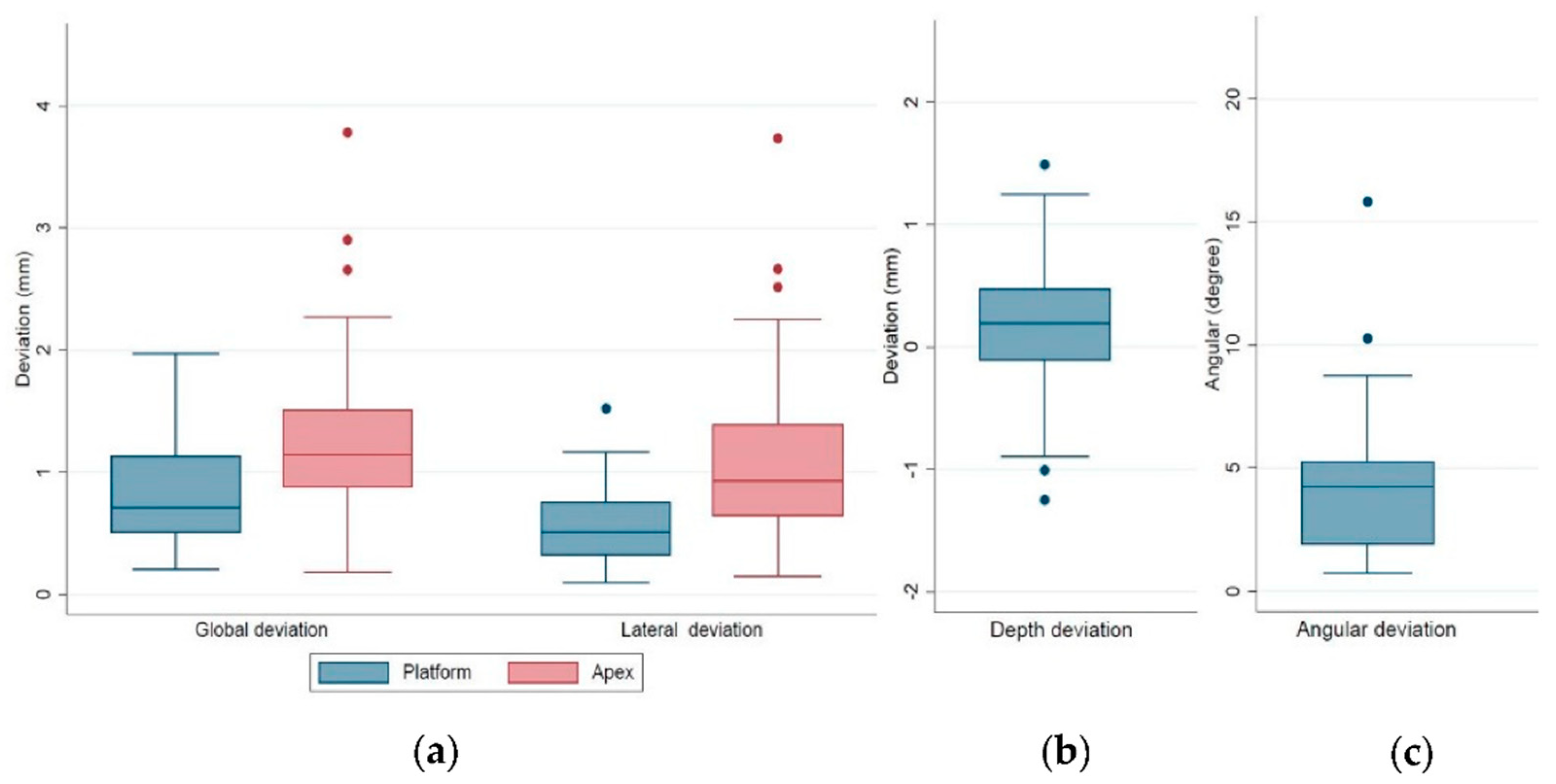
| Total | 43 | 0.78 ± 0.39 | 0.57 ± 0.33 | 1.28 ± 0.72 | 1.14 ± 0.72 | 0.46 ± 0.36 | 4.30 ± 2.87 |
| (range) | (0.20–1.97) | (0.09–1.52) | (0.18–3.78) | (0.15–3.73) | (0.02–1.49) | (0.73–15.83) | |
| Registration protocol | |||||||
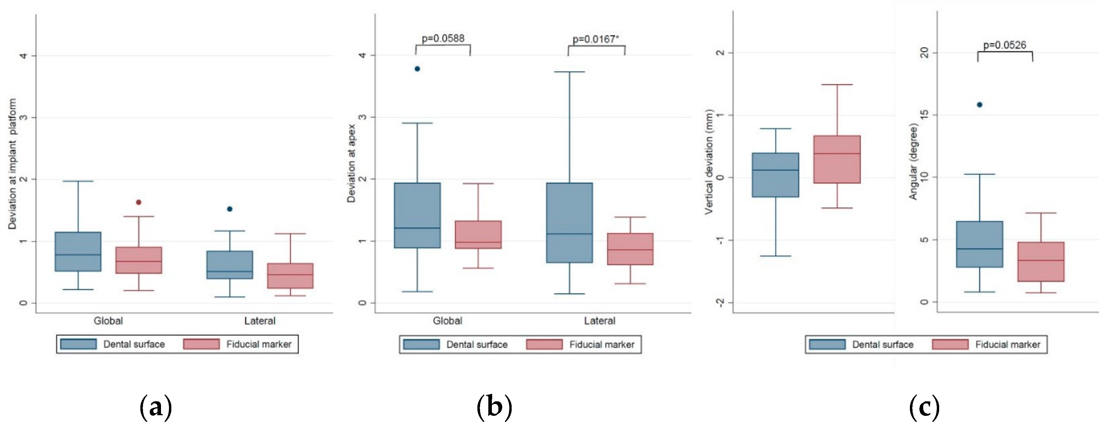
| Dental surface | 25 | 0.81 ± 0.41 | 0.64 ± 0.36 | 1.44 ± 0.87 | 1.34 ± 0.86 | 0.43 ± 0.33 | 4.96 ± 3.32 |
| Fiducial marker | 18 | 0.74 ± 0.38 | 0.47 ± 0.26 | 1.07 ± 0.34 | 0.87 ± 0.30 | 0.50 ± 0.39 | 3.38 ± 1.81 |
| p Value | 0.5620 | 0.1074 | 0.0588 | 0.0167 * | 0.5384 | 0.0526 | |
| Variables | Implant Number | Deviations at Implant Platform | Deviations at Implant Apex | Depth Deviation (mm) | Angular Deviation (Degree) | ||
|---|---|---|---|---|---|---|---|
| Global (mm) | Lateral (mm) | Global (mm) | Lateral (mm) | ||||
| Implant site | |||||||
| Incisor/canine | 9 | 0.58 ± 0.29 | 0.53 ± 0.28 | 1.38 ± 1.08 | 1.35 ± 1.07 | 0.20 ± 0.15 | 4.67 ± 4.42 |
| Premolar | 12 | 0.84 ± 0.35 | 0.61 ± 0.28 | 1.32 ± 0.45 | 1.13 ± 0.52 | 0.53 ± 0.33 | 4.00 ± 2.10 |
| Molar | 22 | 0.83 ± 0.44 | 0.56 ± 0.37 | 1.23 ± 0.69 | 1.07 ± 0.65 | 0.52 ± 0.39 | 4.32 ± 2.57 |
| p Value | 0.2325 | 0.8715 | 0.8506 | 0.6141 | 0.0512 | 0.8750 | |
| Jaw position | |||||||
| Mandible | 25 | 0.85 ± 0.42 | 0.60 ± 0.36 | 1.26 ± 0.67 | 1.10 ± 0.65 | 0.52 ± 0.38 | 4.38 ± 2.56 |
| Maxilla | 18 | 0.68 ± 0.33 | 0.52 ± 0.26 | 1.32 ± 0.79 | 1.20 ± 0.82 | 0.37 ± 0.32 | 4.20 ± 3.33 |
| p Value | 0.1683 | 0.4175 | 0.7685 | 0.6358 | 0.1805 | 0.8481 | |
| Bone quality | |||||||
| Type II | 6 | 0.72 ± 0.30 | 0.58 ± 0.29 | 1.18 ± 0.64 | 1.09 ± 0.64 | 0.36 ± 0.28 | 4.05 ± 2.15 |
| Type III | 29 | 0.80 ± 0.38 | 0.61 ± 0.35 | 1.37 ± 0.79 | 1.25 ± 0.80 | 0.45 ± 0.31 | 4.66 ± 3.25 |
| Type IV | 8 | 0.75 ± 0.52 | 0.42 ± 0.23 | 1.04 ± 0.44 | 0.78 ± 0.22 | 0.57 ± 0.55 | 3.20 ± 1.42 |
| p Value | 0.8841 | 0.3385 | 0.4911 | 0.2564 | 0.5358 | 0.4445 | |
| Implant length | |||||||
| 8/10 mm | 23 | 0.85 ± 0.43 | 0.59 ± 0.35 | 1.27 ± 0.69 | 1.11 ± 0.65 | 0.54 ± 0.39 | 4.62 ± 2.49 |
| 11.5 mm | 11 | 0.76 ± 0.35 | 0.53 ± 0.32 | 1.20 ± 0.47 | 1.02 ± 0.55 | 0.42 ± 0.38 | 3.48 ± 2.06 |
| 13/16 mm | 9 | 0.63 ± 0.31 | 0.55 ± 0.30 | 1.41 ± 1.05 | 1.37 ± 1.05 | 0.28 ± 0.16 | 4.49 ± 4.43 |
| p Value | 0.3496 | 0.8518 | 0.7990 | 0.5464 | 0.1524 | 0.5552 | |
| Implant diameter | |||||||
| 3.5 mm | 3 | 0.52 ± 0.12 | 0.46 ± 0.20 | 0.84 ± 0.21 | 0.81 ± 0.19 | 0.16 ± 0.14 | 2.85 ± 1.28 |
| 3.75 mm | 10 | 0.73 ± 0.32 | 0.57 ± 0.32 | 1.21 ± 0.52 | 1.11 ± 0.56 | 0.36 ± 0.30 | 3.97 ± 1.84 |
| 4.2 mm | 30 | 0.82 ± 0.42 | 0.58 ± 0.34 | 1.35 ± 0.79 | 1.19 ± 0.80 | 0.52 ± 0.37 | 4.56 ± 3.23 |
| p Value | 0.4145 | 0.8514 | 0.4743 | 0.6913 | 0.1544 | 0.5742 | |
| Guide support | |||||||
| Bilaterally | 19 | 0.72 ± 0.37 | 0.57 ± 0.31 | 1.39 ± 0.84 | 1.27 ± 0.86 | 0.37 ± 0.32 | 4.22 ± 3.28 |
| Unilaterally | 24 | 0.83 ± 0.41 | 0.57 ± 0.34 | 1.21 ± 0.63 | 1.06 ± 0.62 | 0.53 ± 0.37 | 4.36 ± 2.57 |
| p Value | 0.3591 | 0.8737 | 0.4388 | 0.3467 | 0.1326 | 0.6510 | |
| Technique | |||||||
| Open flap | 16 | 0.80 ± 0.38 | 0.59 ± 0.25 | 1.41 ± 0.84 | 1.27 ± 0.82 | 0.46 ± 0.41 | 4.75 ± 3.82 |
| Flapless | 27 | 0.77 ± 0.41 | 0.55 ± 0.37 | 1.21 ± 0.64 | 1.06 ± 0.65 | 0.45 ± 0.33 | 4.03 ± 2.17 |
| p Value | 0.7900 | 0.7159 | 0.3979 | 0.3580 | 0.9517 | 0.4970 | |
© 2020 by the authors. Licensee MDPI, Basel, Switzerland. This article is an open access article distributed under the terms and conditions of the Creative Commons Attribution (CC BY) license (http://creativecommons.org/licenses/by/4.0/).
Share and Cite
Lin, C.-C.; Wu, C.-Z.; Huang, M.-S.; Huang, C.-F.; Cheng, H.-C.; Wang, D.P. Fully Digital Workflow for Planning Static Guided Implant Surgery: A Prospective Accuracy Study. J. Clin. Med. 2020, 9, 980. https://doi.org/10.3390/jcm9040980
Lin C-C, Wu C-Z, Huang M-S, Huang C-F, Cheng H-C, Wang DP. Fully Digital Workflow for Planning Static Guided Implant Surgery: A Prospective Accuracy Study. Journal of Clinical Medicine. 2020; 9(4):980. https://doi.org/10.3390/jcm9040980
Chicago/Turabian StyleLin, Chia-Cheng, Ching-Zong Wu, Mao-Suan Huang, Chiung-Fang Huang, Hsin-Chung Cheng, and Dayen Peter Wang. 2020. "Fully Digital Workflow for Planning Static Guided Implant Surgery: A Prospective Accuracy Study" Journal of Clinical Medicine 9, no. 4: 980. https://doi.org/10.3390/jcm9040980