Article

Experimental and Numerical Investigation of the Influence of Process Parameters in Incremental Sheet Metal Forming on Residual Stresses

Chair of Mechanical Design and Manufacturing, Brandenburg University of Technology Cottbus—Senftenberg, Konrad—Wachsmann—Allee 17, Cottbus D-03046, Germany
*
Author to whom correspondence should be addressed.
J. Manuf. Mater. Process. 2019, 3(2), 31; https://doi.org/10.3390/jmmp3020031
Submission received: 15 March 2019 / Revised: 5 April 2019 / Accepted: 8 April 2019 / Published: 10 April 2019
(This article belongs to the Special Issue Analysis and Modeling of Sheet Metal Forming Processes)

Abstract

:
The aim of this study is to analyze the co-relation between the geometrical accuracy of parts formed by single-point incremental forming (SPIF) and the resulting distribution of the residual stresses induced in the material as a function of the different process parameters of the SPIF process. The study was performed for a pyramidal frustum manufactured by varying the process parameters of SPIF, i.e., tool diameter, tool step-down, and wall-angle. The hole-drilling strain gage method was used to determine the residual stresses in the manufactured pyramids. Further, small strips were laser cut from the pyramids, and the curvature of the strips was measured. The curvature of the strips is a result of the intensity and distribution of the residual stresses, which in turn depends on the selected values of the process parameters. A validated numerical model of SPIF was used to determine the residual stresses parallel and perpendicular to the direction of tool motion at the center of a strip cut from the numerical model in clamped, unclamped, and trimmed states. Further, the change in the bending moment of a strip that occurred upon unclamping and trimming was calculated. Experimental and numerical investigations reveal that the most significant parameter in residual stress build-up and the reduction of geometrical accuracy is the wall angle. Upon unclamping, the highest change in the residual stresses and bending moment occurred with the largest tool step-down and tool diameter. Upon trimming, the magnitude of the residual stresses and bending moment changed the most with the largest tool step-down in both directions, whereas the change was highest with the smallest tool diameter in the transverse direction of the tool motion. Furthermore, upon trimming, the geometric deviations were highest with the large wall angles in the transverse direction of the tool motion. Overall, the effect of changing process parameters on the residual stress state and geometrical accuracy was more pronounced in the transverse direction of the tool motion.

1. Introduction

The single point incremental forming (SPIF) process is an advanced flexible manufacturing process, in which a clamped sheet is formed into the desired shape by the movement of a hemispherical tool. The movement of the tool, i.e., the tool path, is controlled by a CNC machine to create the desired shape. The sheet is then locally deformed along the tool path, which covers the part geometry. The sum of these local deformations constitutes the final formed shape of the part [1]. The localized deformation mechanism of SPIF allows the sheet to be stretched well beyond the conventional forming limit curves (FLC) [2]. Hence, due to high deformations, the process is likely to induce high residual stress levels in the formed components. These residual stresses often cause a substantial deviation from the desired target geometry as soon as the parts are unclamped from the blank holder and trimmed to the final shape [3]. The low geometrical accuracy of SPIF is a limiting factor for a wider industrial application of the process [4]. Hence, a better understanding of the residual stresses is necessary to increase the geometrical accuracy of the SPIF.
On the other hand, residual stresses are defined as the internal stresses in a material, present in the absence of external loading. The residual stresses are mainly caused due to local yielding of the material as a consequence of deformation and/or thermal gradients, solid state transformations, as well as volumetric changes occurring during solidification [5]. In the current study, residual stresses are generated due to plastic deformation of the material. The lifetime and integrity of the components are highly affected by the state and intensity of residual stresses. For example, a combination of tensile residual stresses with service stresses adversely affects the fatigue life of the components, whereas compressive residual stresses are beneficial for improving the fatigue life of formed components [6,7]. Furthermore, depending on the nature of the residual stresses, they can cause an early onset of the plastic deformation or postpone yielding [8]. They are also a source of geometric deviations for the plastically formed components [9]. Hence, a better understanding of the induced residual stresses in the material is necessary to overcome these issues and it can further assist in benefitting from these stresses.
A brief review of the literature dealing with SPIF and residual stresses is presented. In this regard, Tanaka et al. [10] analyzed the generation of residual stresses in parts manufactured by SPIF. They used numerical simulations to study the effect of tool diameter and feed rate on the residual stresses. Residual stresses were found to decrease by increasing the tool diameter, whereas the tool feed rate had no significant effect on the residual stresses. Furthermore, they concluded that the state of the residual stresses in SPIF is such that it creates a residual moment that causes negative springback; i.e., upper layers contain tensile residual stresses, and the lower layers have compressive residual stresses. Radu et al. [11] analyzed the residual stresses in double frustums of a cone and a pyramid, which were manufactured from A1050 pure aluminum sheets using varying process parameters. The hole drilling method was used to experimentally analyze the magnitude of the residual stresses. In another study, Radu et al. [12] developed a cause–effect relationship between the process parameters, residual stresses, and the geometrical accuracy. They concluded that the residual stresses decrease by increasing the tool diameter and spindle speed, whereas the residual stresses increase by increasing the tool step-down and feed rate. The nature of the stresses was shown to be varying from compression to tension throughout the thickness of the sheet. In a recent study by Jimenez et al. [13], X-ray diffraction was used to measure the residual stresses on the inner and outer surfaces of the side walls of a pyramidal frustum with a continuously varying wall angle. The nature of the residual stresses was found to be like that of previous studies, i.e., tensile stresses on the upper contact layers and compressive stresses on the non-contact bottom layers. They also calculated the magnitude of the bending stress analytically. The magnitude was found to be in the range of the yield stress of the material, which was attributed as a factor for the occurrence of a crack on the outer surface of the part. Furthermore, the driving force for the grain boundary migration was found to be of the same magnitude as that of the residual stresses. Contrary to the tension-compression nature of the residual stresses in SPIF, the nature of the residual stresses was found to be compressive in deformation machining, i.e., a combination of thin wall machining followed with SPIF by Singh et al. [14]. Further, most recently, Shi et al. [15] studied the residual stresses in incrementally formed Cu/steel bonded laminates using the hole-drilling method. The nature of the residual stresses was completely compressive, with magnitude decreasing from one end to the other end along the thickness section (i.e., from the tool contact side to the non-contact side). The most significant process parameters were tool diameter and wall angle, while the tool rotation was the least significant process parameter in terms of the effects on the residual stresses.
In SPIF, because of the tension-compression nature of the residual stresses, a significant amount of distortion occurs upon unclamping and trimming. In this regard, various approaches have been presented in the literature to increase the geometrical accuracy by reducing the intensity of the residual stresses. For example, Behera and Ou (2015) [16] showed that the geometrical accuracy and surface finish for the incrementally formed parts from grade 1 titanium sheets increases by using heat treatment. Further, authors have presented strategies to improve the geometrical accuracy using stress-relief annealing [3,17]. A significant improvement in the geometric profile was observed. Mohammadi et al. [18] used laser-assisted annealing on incrementally formed parts. A finite element model was used for the determination of the optimal annealing parameters, i.e., laser power, scanning speed, and beam spot size. They showed that the geometrical accuracy can be increased, and the intensity of the residual stresses can be decreased by using laser-assisted annealing.
The residual stresses have a significant effect on the geometrical accuracy in SPIF. Different strategies have been discussed from the literature that analyze the intensity of the residual stresses and its effects on the geometrical accuracy. It is important to consider that all these strategies only analyze the final state of the residual stresses, i.e., an unclamped or a trimmed state. The effect of the process parameters on the residual stresses have also been analyzed in the same way; i.e., only the final stress state has been taken into consideration. The analysis of the residual stresses only in the final state is not sufficient because the change in the residual stresses occur threefold in the SPIF process, i.e., during the actual process, upon unclamping, and upon trimming. Hence, to better understand the role of the residual stresses on the geometric deviations, insight into the development of the residual stresses during the entire SPIF process is necessary. Until now, this information has been missing in the literature. The current study bridges this knowledge gap in the literature and analyzes the state of residual stresses during the entire SPIF process, i.e., before and after unclamping and in the final trimmed state. Similarly, the effect of the process parameters on the residual stresses has also been studied for the entire SPIF process. Further, literature on the SPIF suggests that the geometrical accuracy can be increased by using smaller tool diameter, a smaller tool step-down, and thicker sheets [19,20]. An explanation of these conclusions in the scope of the state of the residual stresses is missing.
The first objective of the current study is to determine the effects of the major process parameters, i.e., tool diameter, tool step-down, and wall angle, on the state, i.e., the intensity and distribution of the residual stress. The second objective is to analyze the deviations of the incrementally formed parts under different combinations of the process parameters and explain these geometric deviations in terms of the residual stresses. To achieve these objectives, a new methodology is introduced. A direct measure of the residual stresses in the formed pyramids is obtained by cutting small strips from these pyramids. The bending of the cut strips occurs due to the magnitude of the residual stresses, and the curvatures of the strips cut from the pyramids, which are manufactured by varying the process parameters, are compared to determine the intensity of the residual stresses. Further, numerical simulations are used to analyze the cut strips for the intensity of the residual stresses and the geometrical accuracy. These strips are cut similar to the experimental approach, and the residual stress analysis is carried out at the center of the strips. All numerical results are validated by the experiments. Hence, the second objective of the current study is achieved.

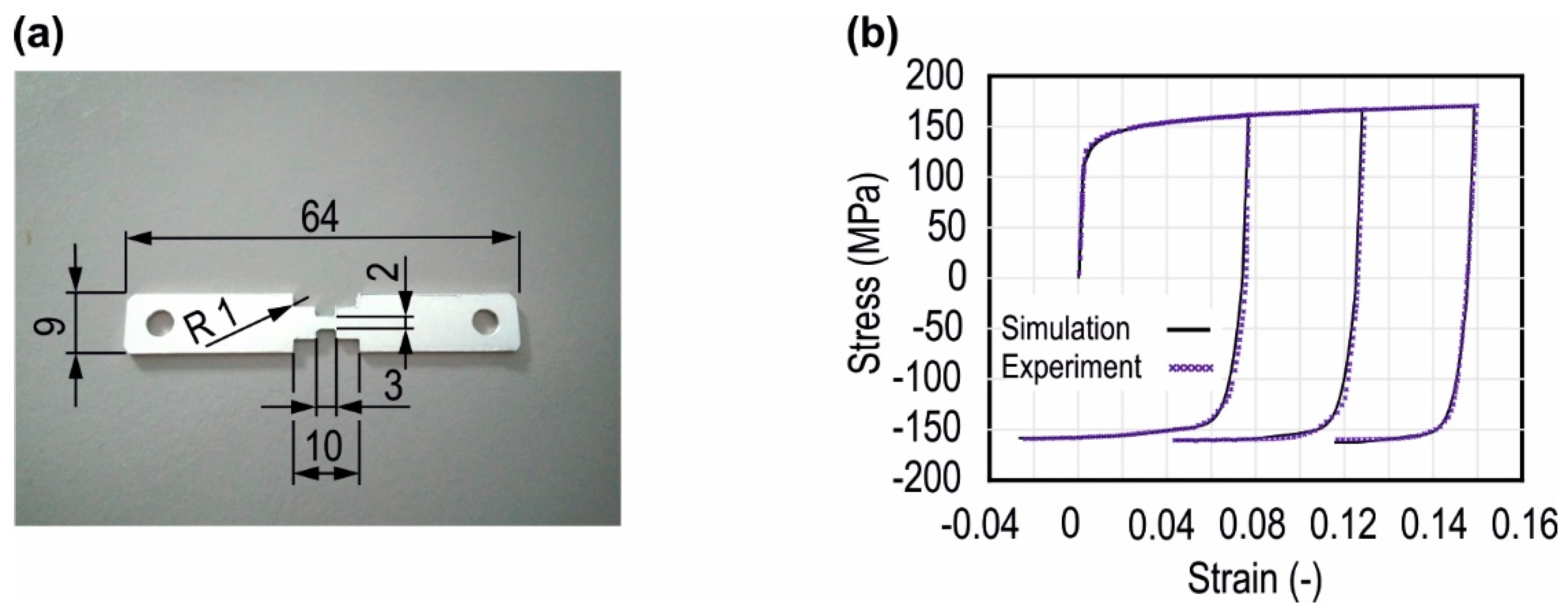
2. Materials and Method

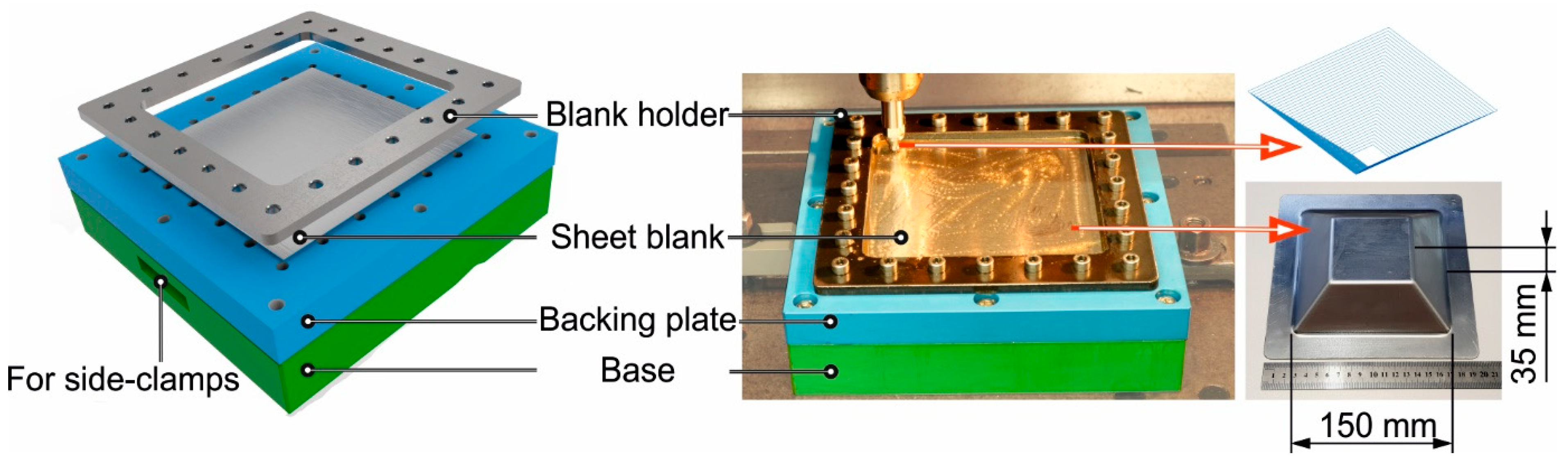
2.1. Experimental Set-Up of SPIF

The pyramidal parts were manufactured from the sheets of aluminum alloy EN-AW-5005 having a thickness of 1.5 mm and a size of 200 × 200 mm. The SPIF process was carried out on a 3-axis CNC milling machine. The experimental set-up is presented in Figure 1. The SPIF experimental set-up consists of a blank holder, a backing plate to increase the geometrical accuracy, and a low cost base manufactured from A Sika® block. The sheet blanks are clamped between the blank holder and the backing plate. The hemispherical tool follows a sequence of square paths to manufacture the pyramidal frustum. The dimension of the manufactured pyramids is 150 × 150 × 35 mm (Figure 1). Pyramidal parts are manufactured by systematically varying process parameters. The varied parameters are tool diameter, tool step-down, and the wall angle. The design of experiments (DoE) is presented in Table 1. For three different values of the three process parameters, a total of 7 experiments are required to analyze the effect of each value of the process parameter.
To analyze the geometry of the formed parts after forming, a circular pattern was etched on the outer surface of the original sheet blanks. The pattern was in the form of circular grids placed at a distance of 2 mm and having a size of 1 mm. The sequence of the digitization and measurement of the strains is presented in Figure 2. A 3D forming analysis system ARGUS® by GOM GmbH, was used to digitize and analyze the respective principle strains.
The deviations upon trimming the final form of the part are due to the residual stresses. A quick measure of the intensity of the residual stress in the pyramidal parts under the influence of changing process parameters can be determined by cutting small strips from the side walls of the pyramids. The curvature appearing in the strips will be directly proportional to the intensity of the residual stresses. The higher the curvature is, the more intense the residual stresses are. Strips were cut in both directions of the tool motion using a 3D laser cutting center. After trimming, these strips exhibited a curvature that depends on the magnitude of the residual stresses in the individually cut strips. Hence, by measuring the curvature of these strips, the interdependence between the process parameters of SPIF, the resulting residual stresses, and the geometrical accuracy can be determined. One of the cut strips is presented in Figure 3b. The dimensions of the strips cut along the tool motion direction are 60 × 17 mm, and those of the strips cut for the strips cut in the transverse direction are 30 × 10 mm. The center of the strips and the center of the side walls of the pyramids are always identical (Figure 3a). It is important to mention that laser cutting influences the mechanical properties of the material, but these effects are concentrated around the edges of the strips being cut, and the thermal gradients drops sharply with the distance from the cutting edge [21]. Considering the dimensions of the analyzed strips, which are large enough to minimize the effect of thermal gradients created due to laser-cutting, the curvature that appears is due to residual stresses in the entire strip. There will be stress relief due to laser cutting that is concentrated along the edges of the strip, with a minimal effect on this curvature. The curvature was measured using a Home-Etamic T8000 contour measurement system. The system uses a measuring stylus connected to the machine head for measuring the curvature on the strips (Figure 3c).

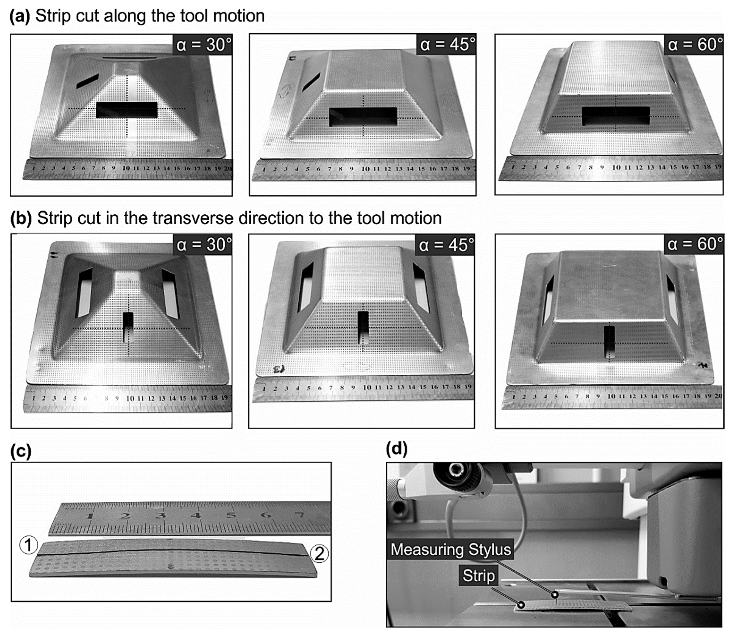
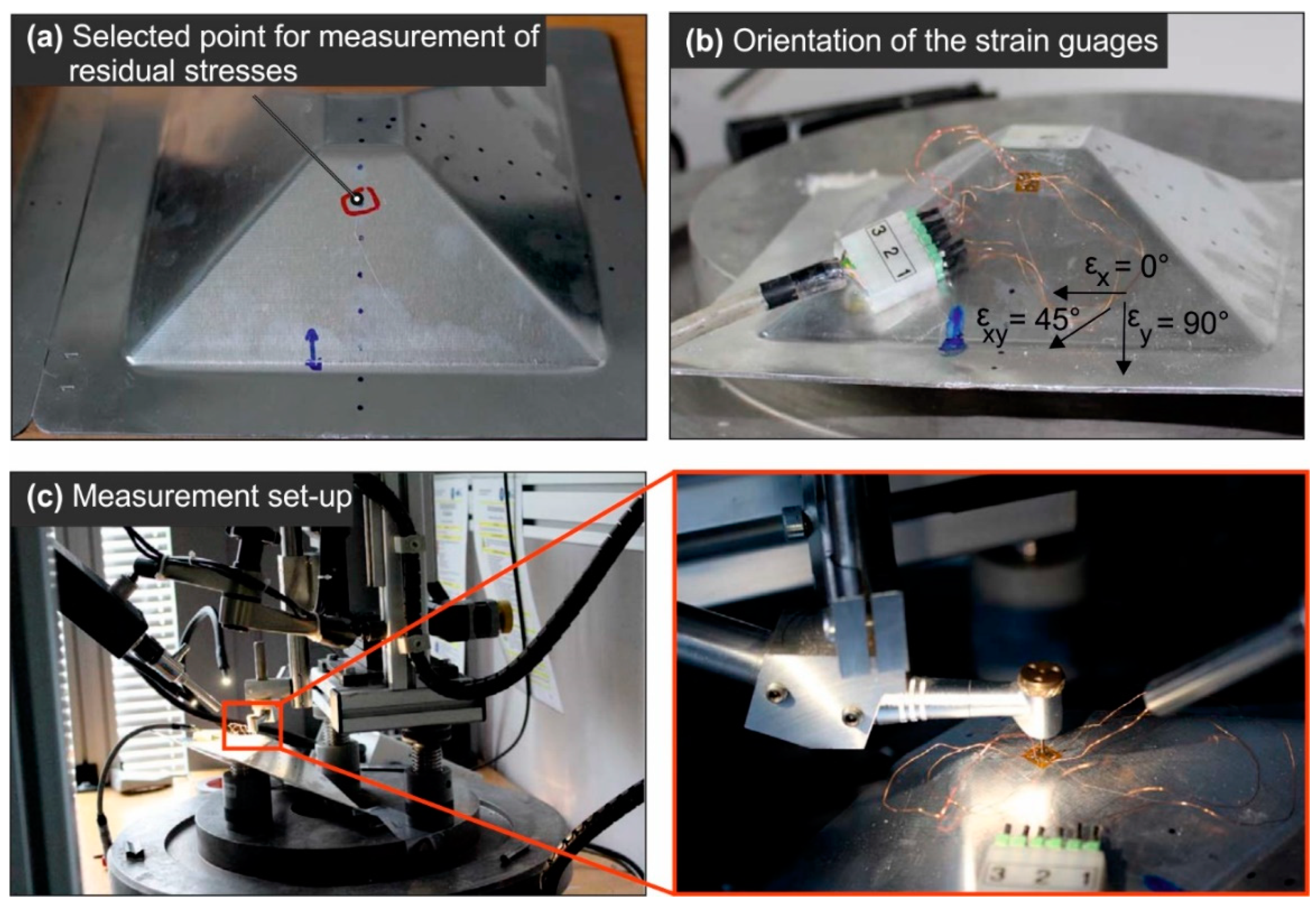
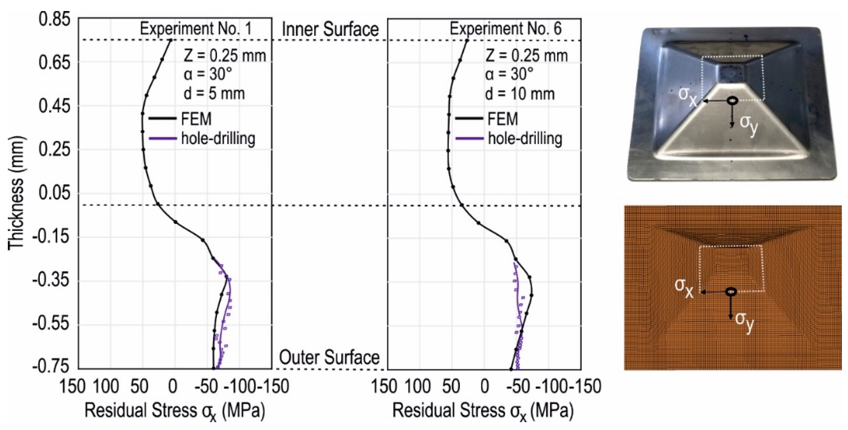
2.2. Hole-Drilling-Method

The hole-drilling method is a conventional technique used to determine residual stresses in different materials [22]. The residual stresses in the manufactured pyramids are measured using this method. The method consists of incrementally drilling a small hole into the specimen and recording the respective relief of the strain using a strain-rosette. For the current study, the residual stress analyzer system from the company MTU® was used. A drill head of 0.8 mm rotating at 200,000 rpm was used to determine the residual stresses at the specified location (Figure 4a), containing an attached strain-rosette (Figure 4b). The high rotations of the drill head suppressed the creation of the supplementary stresses. The calculation steps for the residual stress values were automatically adjusted along the depth of the drilled hole. The stresses are calculated from the measured strain by using the relation [23]
σ x , y =   E { ε x +   ε y 4 A ±   1 4 B ( ε x ε y ) 2   +   [ 2 ε x y ( ε x + ε y ) ] 2   }
where E   represents elastic modulus, and A , B   are constant, and their values are provided by the manufacturer of the residual stress analysis system. ε x ,     ε y , and ε x y are strains along and in the transverse direction of the tool motion and at 45° (Figure 3b). σ x   and σ y are the stresses corresponding to ε x and ε y strains, respectively. The in-plane shear stress can be further calculated using the following relation
σ x y = ( σ x   σ y ) / 2 .
The out of plane residual stresses, i.e., stresses through the thickness direction, along the z-axis cannot be measured by this method and hence are neglected. This is also a common simplification for most of the sheet forming processes, where the thickness of the sheet is normally less than 3 mm.

2.3. The Finite Element (FE) Model of the SPIF Process

The major disadvantage associated with the hole-drilling method is that it provides the values of the residual stresses locally and is extremely time-intensive, from setting up the experiment to post-processing. Hence, an FE model of SPIF was first validated in terms of the residual stresses and then employed to examine the distribution of the residual stresses in the whole model.
An element size of 1 mm was selected for the numerical model. The model is discretized using shell elements. An important aspect for the FE model of the SPIF process is an accurate description of the tool trajectories. A displacement-based tool trajectory can induce artificial energy jumps in the numerical model, e.g., when the tool changes its direction. To overcome this issue, a MATLAB script is used to convert the time-displacement curves to time–velocity curves [24]. The original G-code used for the manufacturing of each pyramid from the experiments (Table 1) was used to generate these curves for each simulation. Further, the blank holder and the tool are modeled as rigid bodies.
In terms of the accuracy of the FE model, a key factor is the choice of the hardening model. In the current study, a combined hardening model according to the work of Chaboch-Roussilier [25] is employed. This material model accurately predicts the behavior of the material in terms of thickness reduction, forming forces, and residual stresses [26,27]. The evolution equation for this hardening model is
α ˙ i j = C ( γ   S i j σ e f f α i j ) ε ˙ p
where α i j is the back stress component, S i j is the deviatoric stress, σ e f f is the effective stress, and ε p ˙ is the effective plastic strain rate. The hardening model has two parameters. The parameter C and γ describes and controls the rate of kinematic hardening modulus.
These material constants were determined using an inverse FE-approach. In this regard, tension-compression tests were carried out on a deformation dilatometer. The geometry of the specimen used is represented in Figure 5a. The dimensions of the specimen are kept small to avoid buckling. The tests were carried out at three different strain levels. The resulting cyclic curves are used as target curves to determine the material constants. The optimization for the material constant is done in LS-OPT and by using LS-Dyna as a solver. The simulation model consists of a single element model with eight nodes. Using a full numerical model of the tension-compression test sample for optimization is computationally not feasible.
Response surface methodology (RSM) is used in the optimization procedure for the determination of the material parameters. A curve mapping algorithm reduces the respective area between the experimental and numerical stress–strain curves, until a good match is found between both curves. A comparison of the experimental and optimized numerical cyclic stress–strain curves is presented in Figure 5. An optimized value of C = 320   MPa and γ = 70 was found.

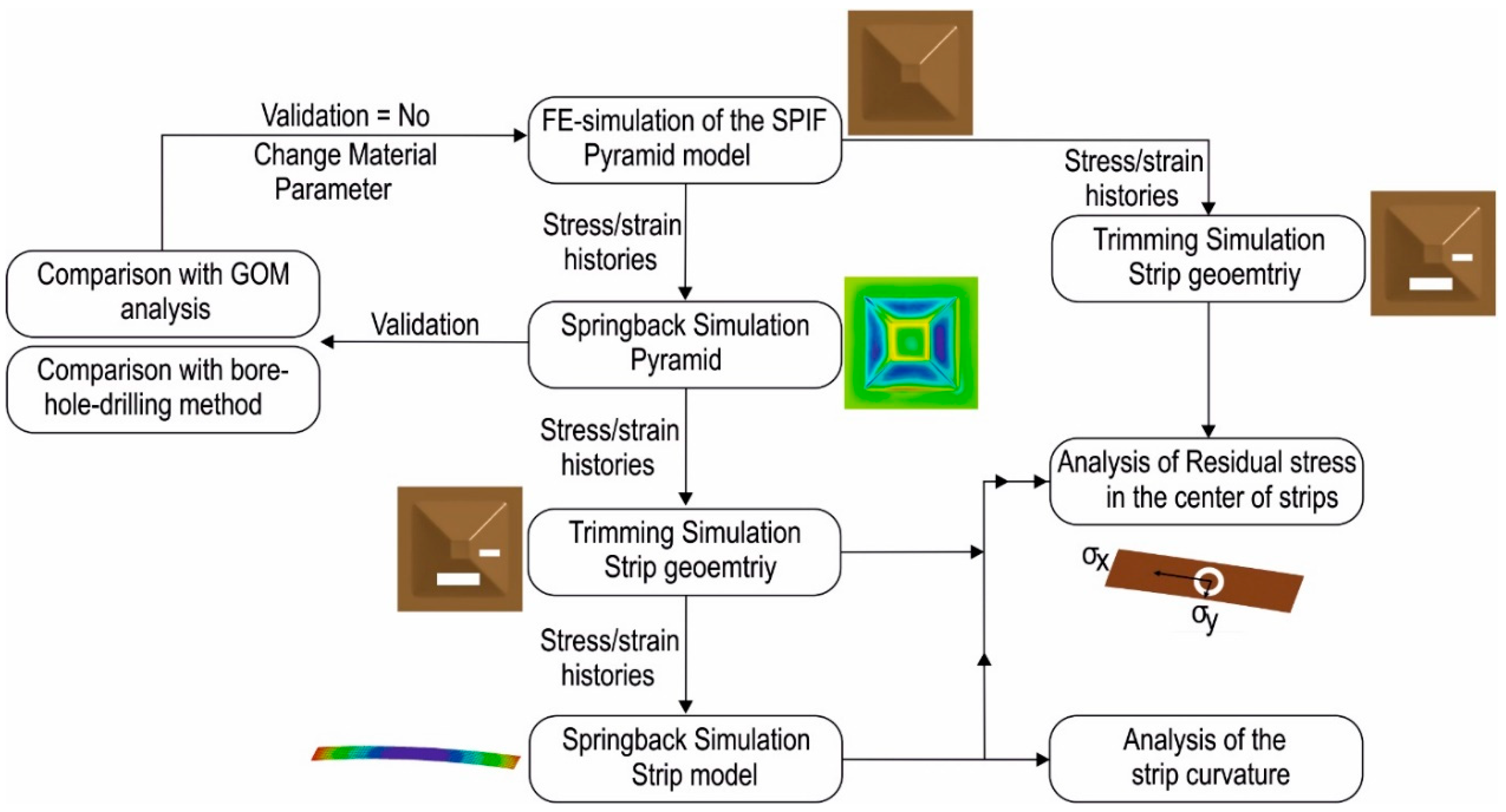
2.4. Solution Procedure

This section details the procedure that was developed to combine the experimental data obtained from the previous sections (Section 2.1 and Section 2.2) with the numerical simulations (Section 2.3) to achieve the objectives of the current study. The step by step procedure to analyze the residua stresses is presented as a flow chart in Figure 6. After the completion of the numerical simulation, an input file is created from the simulation of the each pyramid that contains the complete stress–strain history at all integration points for all elements. A trimming simulation is set up using this input file, where a strip with dimensions corresponding to the experimentally cut strip (Section 2.1) is trimmed from the pyramid. During the trimming simulation, new elements are created along the edges of the strip. An adaptivity algorithm is used to map the results, i.e., stress–strain histories of the newly created elements. The resulting distribution of the residual stresses in the center of the strips is analyzed for each simulation. This is equivalent to analyzing the residual stresses in the clamped model.
The next step is the verification of the numerical model described in Section 2.3. The verification is carried out two-fold. The stress–strain histories from the numerical model of the pyramid at the last time step are exported to set up a springback simulation. After the springback simulation, the numerical results are compared with the data obtained after digitizing the formed geometry of the pyramids (Section 2.1). Furthermore, the residual stresses measured at a specific point with the hole-drilling method (Section 2.2) are compared with a point at the same location from the numerical simulations. In case of a no match between the experimental and numerical values, the model parameters like friction and contact definitions are changed and the model is run again. This is repeated until a good match is found between the experiment and numerical simulations.
After validation, springback simulations are carried out for all the experiments (Table 1). Further, a trimming simulation similar to the first step is set-up using the respective stress–strain histories from the springback model. The trimming simulation is used to cut a strip from the numerical model of the pyramid. The dimensions of the numerically cut strip are similar to those of the experimentally cut strips from Section 2.1. The resulting residual stresses are analyzed in the center of the strip. This is equivalent to analyzing the residual stresses in the unclamped model. In the last step, the springback simulation is carried out for the strips trimmed from the springback model. Again the resulting distributions of the residual stresses are analyzed in the center of the strips. This is equivalent to analyzing the residual stresses after trimming the final formed part.
The magnitude and distribution of the residual stresses for each process parameter in the strips cut in clamped, unclamped, and trimmed states are analyzed and compared. The geometric deviation is dependent on the change in the bending moment at the unclamping and trimming stage. Therefore, the change in the bending moment is calculated for the strip cut in the transverse direction to better clarify the results of the residual stresses. Finally, the target geometry and the final formed geometries of the pyramids obtained from the optical strain measurement system are used to determine whether the geometrical accuracy in the unclamped state increases or decreases by increasing or decreasing the values of the selected parameters, i.e., tool diameter, tool step-down, and wall angle. The next sections detail the results and conclusions obtained from the current study.

3. Results and Discussions

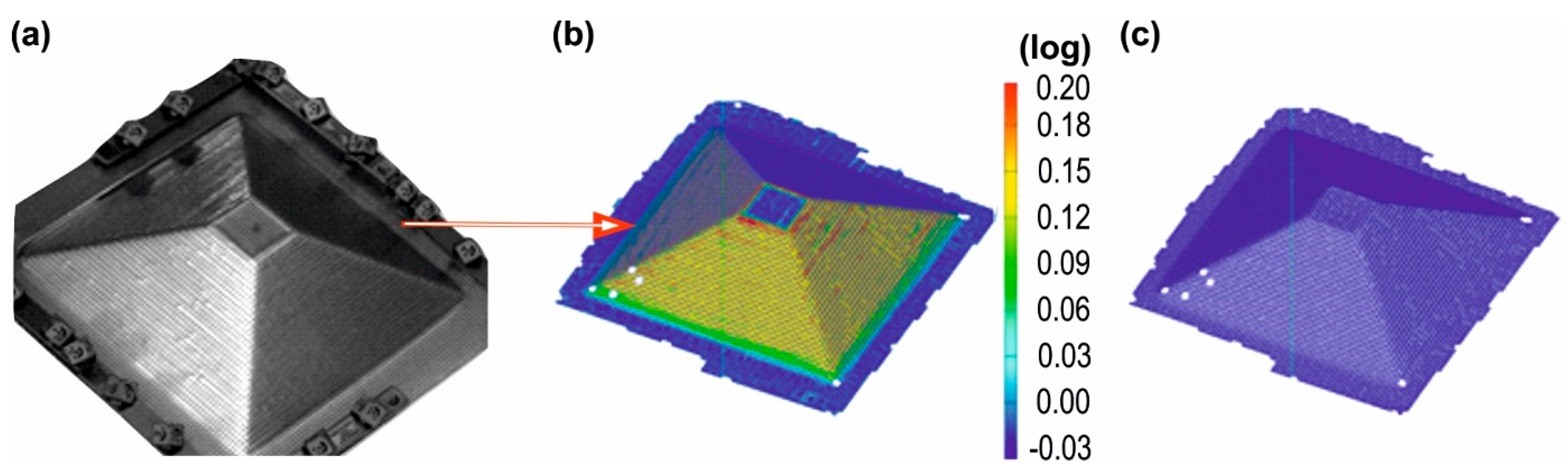
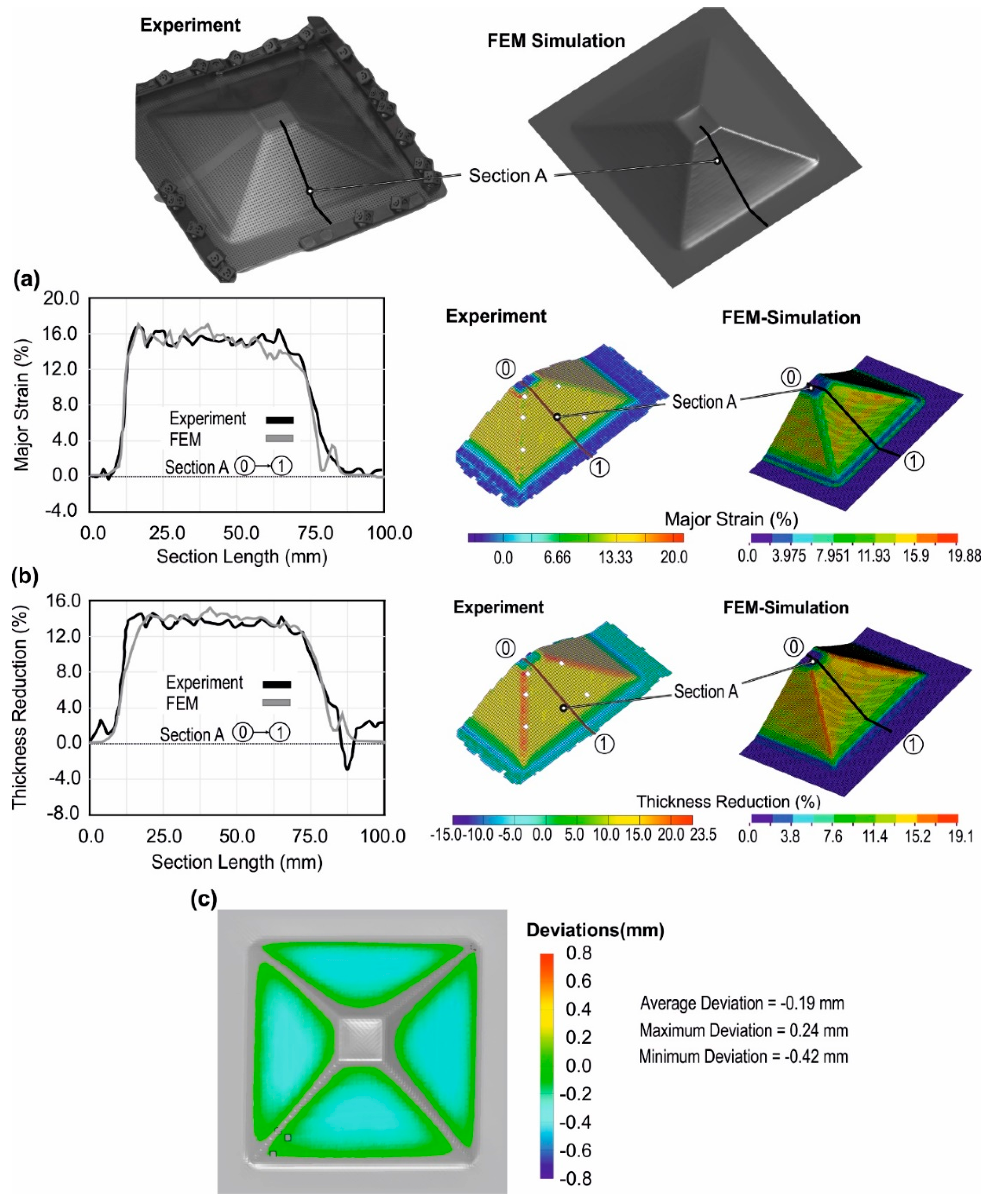
3.1. Validation of the Numerical Simulation

The numerical model of the SPIF process was validated using the experimental data obtained from the optical strain analysis. The results obtained from digitizing the pyramidal parts are major and minor principle strain, thickness reduction, and the formed surface that can be exported from the software ARGUS®. The final formed geometry was exported as a triangular mesh and can be further converted into common formats of CAD geometry i.e., iges or step data. As a basis of comparison, the major principle strains, thickness reduction, and the formed geometry of the part were considered. The results of the major principle strain and the thickness reduction from the experiment and simulation were compared along a section on the part, whereas the side walls of the pyramids were used to compare the experimental and numerical geometry. This is due to the fact that the geometric deviations along the corners and edges of the pyramids are negligible and are most pronounced in the side wall region.
The respective results are output from the numerical model of the pyramids after the springback simulation. The resulting comparison is presented in Figure 7. The comparison was carried out for all experiments, i.e., 7 parts in total. A good comparison was found between the two quantities from the experiment and numerical simulations. The results of the comparison are presented in Figure 7 for Experiment 1. A similar trend, i.e., a good match, was found between the experiments and simulation for all other experiments.
A comparison of the residual stress values between experiments and numerical simulations was carried out at the location used for extracting the experimental residual stress values using the hole-drilling method. This was to identify whether the numerical model is capable of providing an accurate description of the residual stresses. The numerical residual stresses were plotted at all 19 integration points for a single point along with the experimental residual stress values. The comparison of the residual stresses in Figure 8 indicates that the numerical model provides a good representation of the residual stresses.
The numerical model of the pyramid was validated by comparison of the FEA and borehole method. There is a good match between the experimental and numerical data. The state of the residual stresses obtained from the numerical simulation and experimental study validates the findings of previous studies [10,11]. The nature of the residual stresses changes through thickness from the tension on the tool contact side to the compression on the non-contact side. The respective magnitude of the residual stresses is higher in compression as compared to the tension.

3.2. Influence of Process Parameters on Residual Stresses

After the validation of the numerical model in terms of the residual stress, the next step is to analyze the behavior of the residual stresses under changing process parameters. In this regard, numerical simulations corresponding to all the experiments were carried out. Strips containing the respective stress–strain histories of the elements at each of the 19 integration points were cut before and after the springback simulations. Springback simulations were further performed for the strips that were cut from the springback model of the pyramid. The procedure is represented as a flow chart presented in Section 2.4. The respective through thickness distribution of the residual stresses at the center of the strips and at 19 integration points was plotted for both directions of the tool movement, i.e., σ x and σ y . The upper surface was in contact with the forming tool, and the lower surface was the non-contact surface.
It is important to mention that the changes in the stress state occurred at two stages in the manufacturing of the pyramids, i.e., upon unclamping and trimming. The material changed its equilibrium state and caused a change in the state of the residual stresses [20]. In both cases, the respective boundary conditions were changed, which was followed by a change in a stress state that further caused a change in the geometry of the part. In a previous publication [28], the authors pointed out that the geometric deviation is dependent on the contribution of the bending deformation mode. The higher the change in the bending moment between stages, the higher the geometric deviations will be. Hence, in order to better understand the residual stress and the impact on the geometrical accuracy, the respective change in the bending moment at these two stages was determined. Stage 1 is defined as the change in the bending moment between the clamped and unclamped state. Stage 2 is the change in bending moment between unclamping and trimming stage. The values were plotted along a section on a strip cut in the transverse direction of the tool motion.

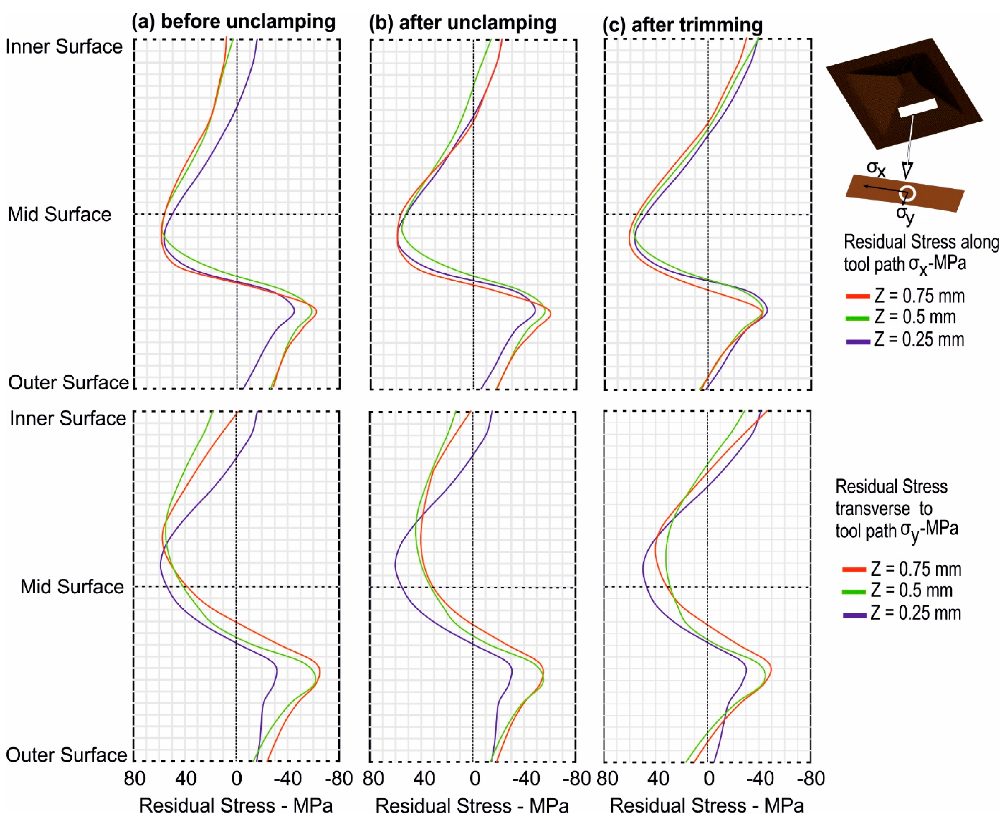
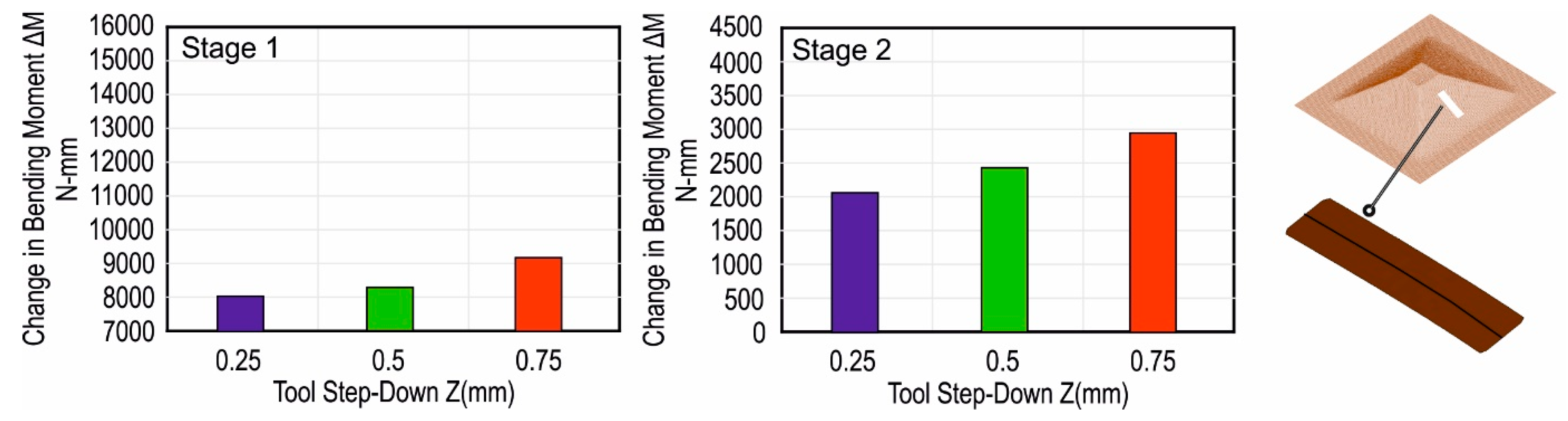
3.2.1. Tool Step-Down

The distribution of the residual stresses along the thickness and in the center of the strips is presented for tool diameters in Figure 9. Important observations from Figure 9 are as follows:
  • By increasing the tool step-down, the magnitude of the compressive residual stresses on the non-contact surface increased more compared to tensile stresses on the tool contact side as indicated by the ‘before unclamping’ state.
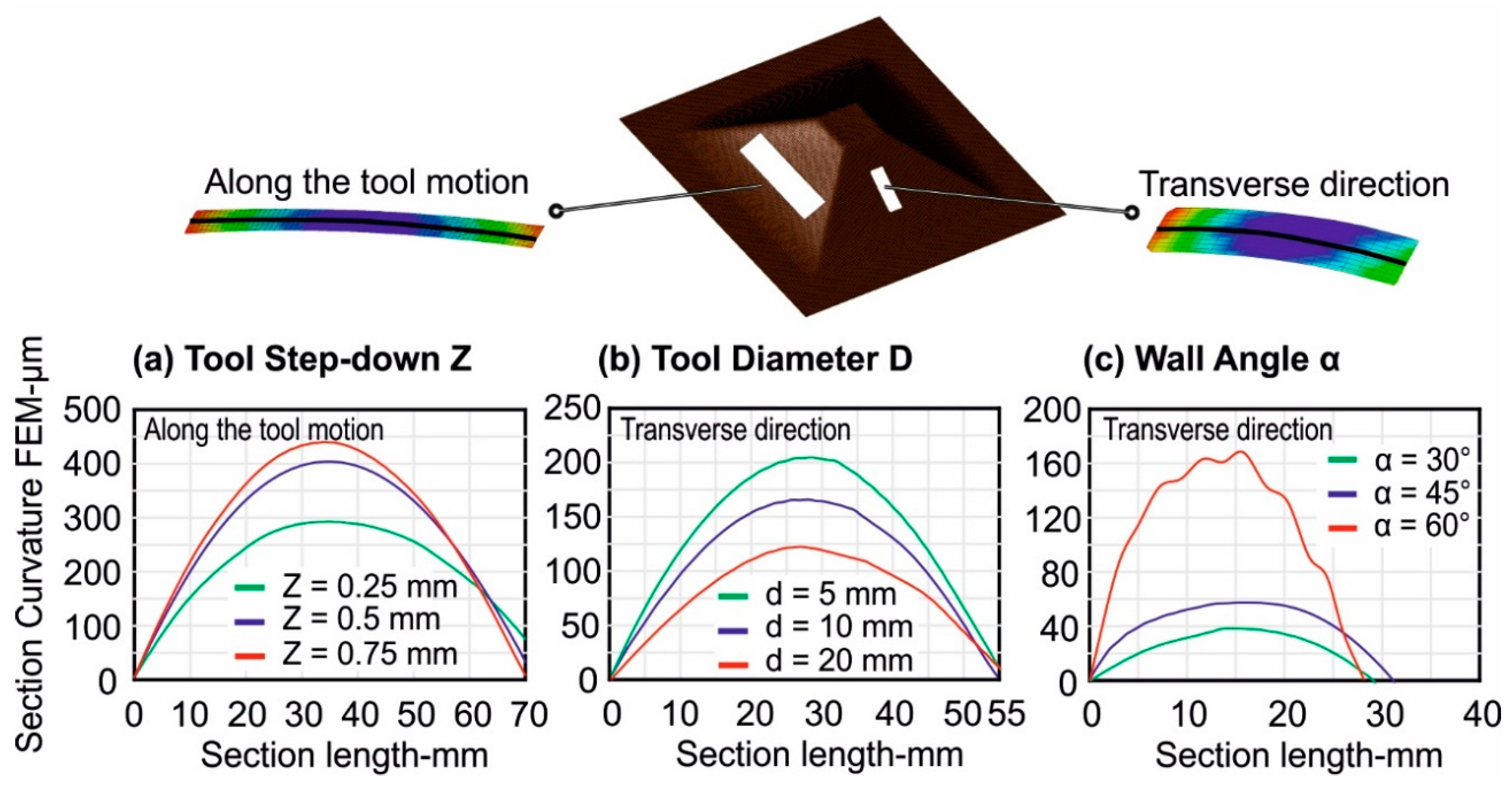
  • For larger tool step-down values, the magnitude of the residual stresses changed more upon unclamping in the transverse direction of the tool motion.
  • The change in the magnitude of the residual stresses was greater upon trimming compared to unclamping. There was also a significant change in the magnitude of the residual stresses for outer and inner surfaces. The final state of the residual stress after trimming for the inner surface was compression, similar to the initial unclamped state, i.e., before unclamping and vice-versa for the outer surface.
Further, the change in the bending moment occurring upon unclamping and trimming is presented in Figure 10. An important observation is as follows:
  • The bending moment change was highest with the largest tool step-down and vice-versa. Therefore, the geometric deviations will be highest with the largest tool step-down.
The highest change in the magnitude and state of the residual stresses upon unclamping and trimming occurred with the largest tool step-down values and vice-versa. This was validated by plotting the respective changes in the bending moment. The change in the bending moment is proportional to the change in the residual stresses. Hence, the largest geometric deviations, i.e., the largest curvature, should be obtained with the largest tool step-down. The final stress state of the strip after trimming is such that the inner face that is in contact with the tool will be under compression and the outer face will be under tension. These observations are validated in the next section based on the curvature of the laser-cut strips from Section 2.2.

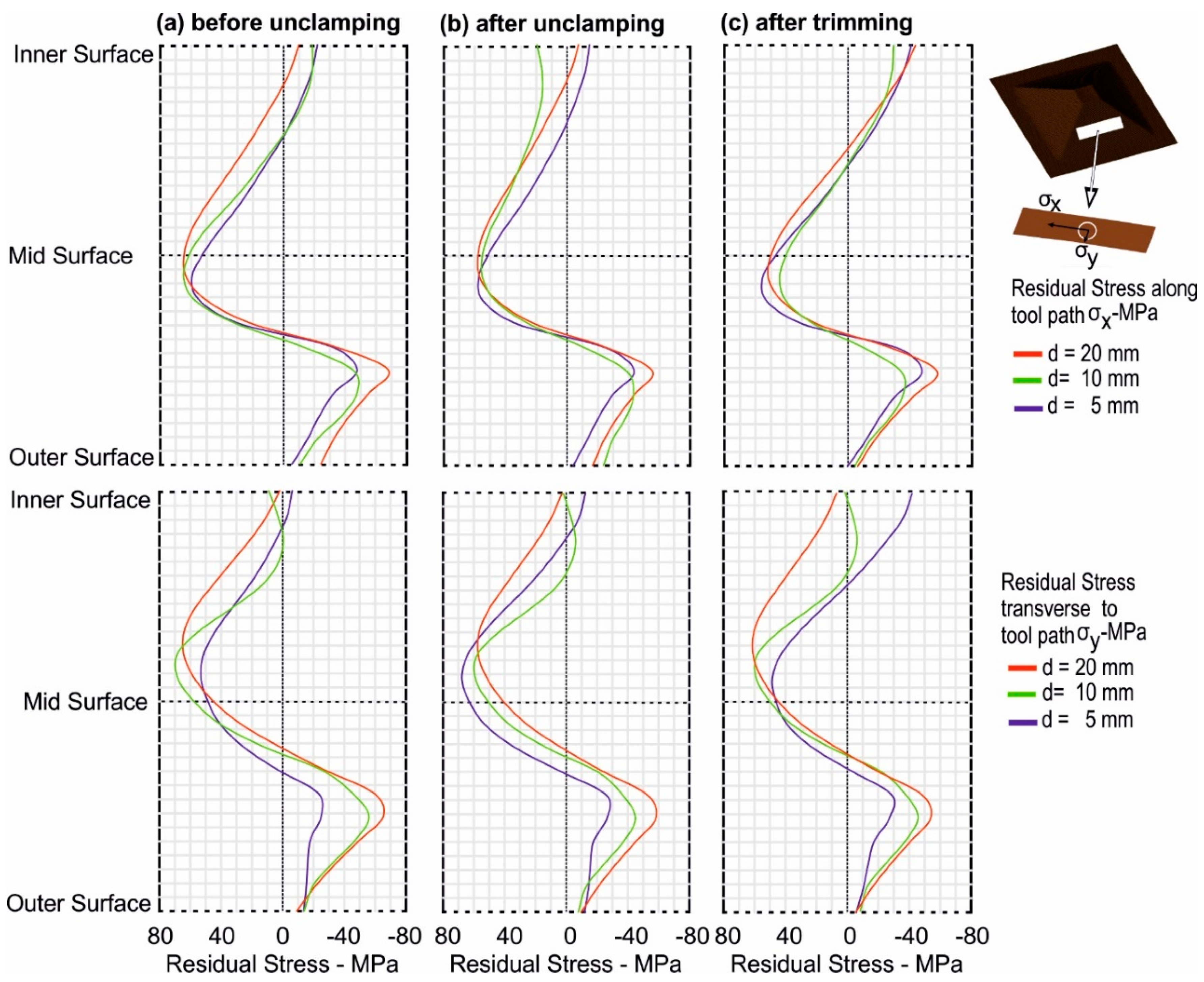
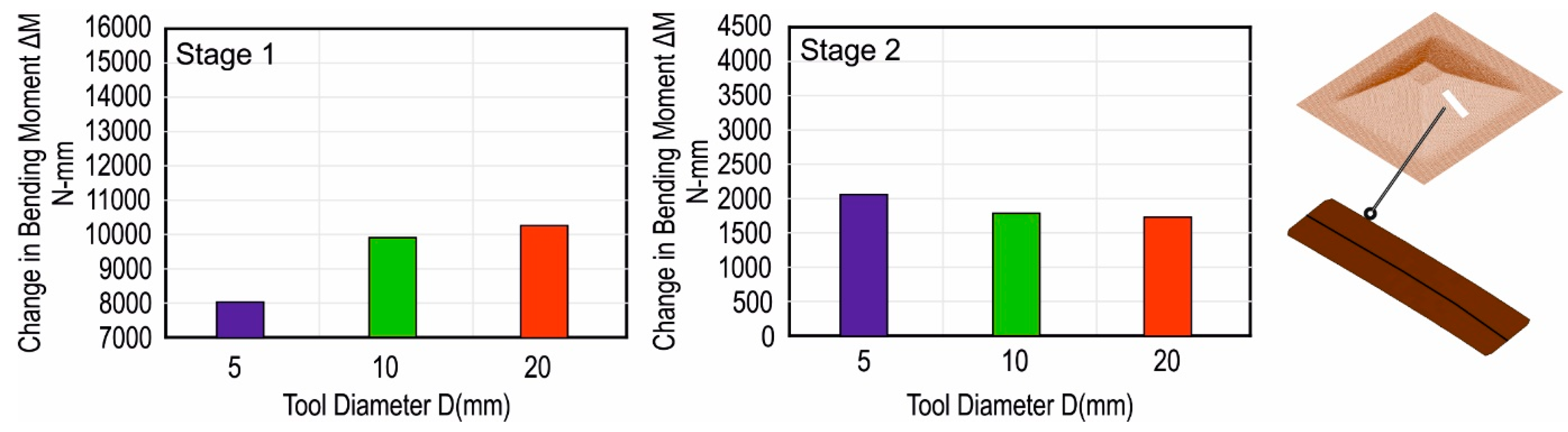
3.2.2. Tool Diameter

The distribution of the residual stresses along the thickness and in the center of the strips is presented for tool diameters in Figure 11. Important observations from Figure 11 are as follows:
  • In the initial clamped state, the magnitude of the residual stresses, by increasing the tool diameter, increased both in tension and compression.
  • The ‘before unclamping’ state indicates that the residual stress, by increasing the tool diameter, increased more pronouncedly in the transverse direction of the tool motion.
  • A notable change in the transverse direction in the magnitude and state of the residual stresses occurred upon unclamping, represented by ‘after unclamping’ in Figure 11, and this change was largest with the largest tool diameter.
  • Upon trimming, the respective change in the magnitude of the residual stresses was slightly larger with the smallest tool diameter.
Further, the change in the bending moment occurring upon unclamping and trimming is presented in Figure 12. Important observations are as follows:
  • The change in the bending moment was highest with the largest tool diameter upon unclamping in the transverse direction.
  • The change in the bending moment was highest with the smallest tool diameter upon trimming in the transverse direction.
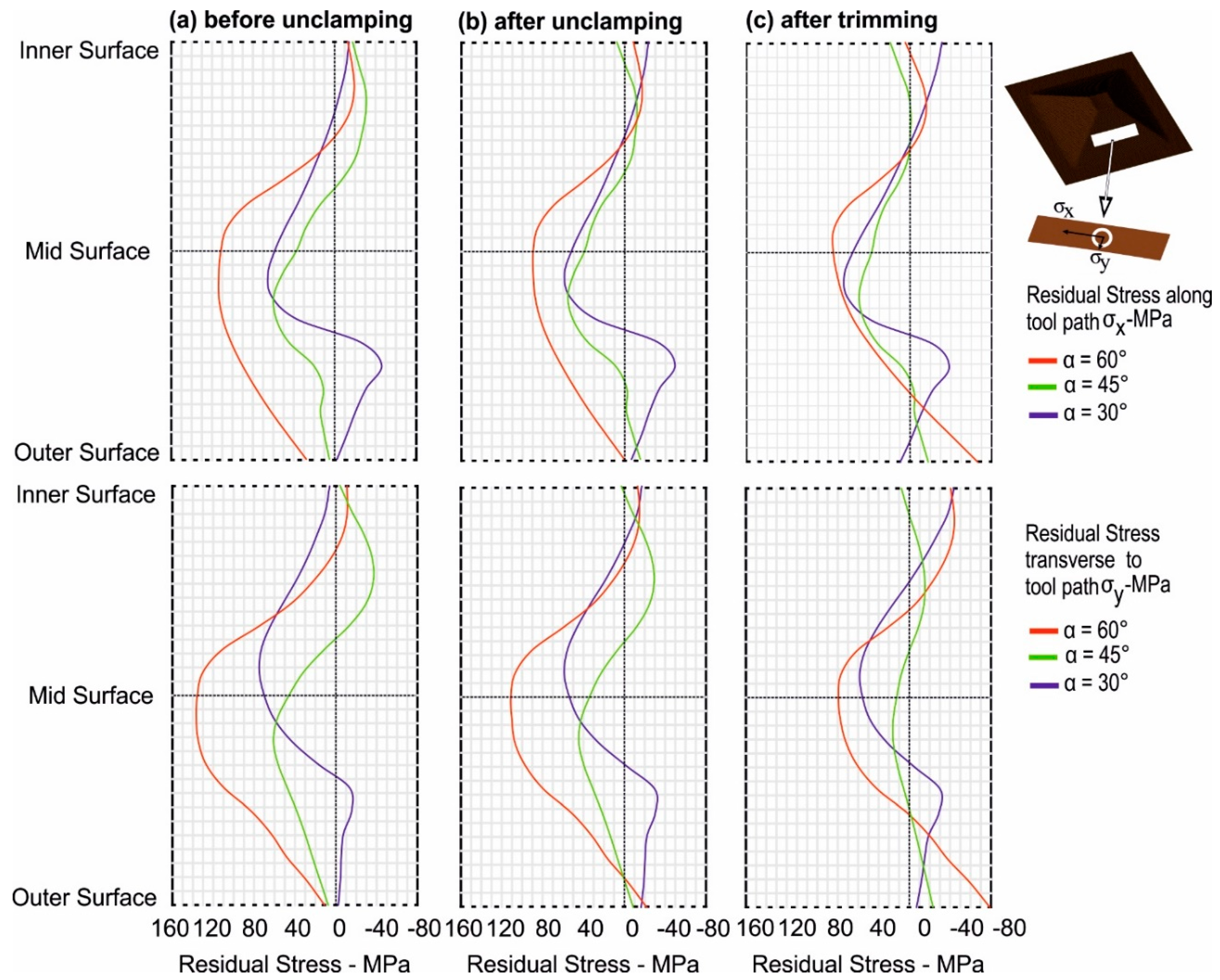
It can be concluded that the highest change in the magnitude of the residual stresses upon unclamping occurred with the largest tool diameter. This is validated by the change in the bending moment in Figure 12. The change in the bending moment upon unclamping was highest with the largest tool diameter. Therefore, the unclamped accuracy of a part formed by SPIF should increase when decreasing the tool diameter. A different observation was made after trimming the strips. The respective change in the magnitude of residual stress and bending moments was slightly larger with the smallest tool diameter, as compared to the largest tool diameter. Hence, upon trimming, the respective geometric deviation, i.e., the strip curvature, will be slightly larger for smaller tools than for larger ones. This observation is further validated in the next section by comparing the resultant displacements of the strips that occur upon trimming (Section 3.3).

3.2.3. Wall Angle

A different behavior of residual stresses as compared to the tool diameter and tool step-down was found by increasing wall angle values. The resulting distribution of the residual stresses for three different states and for three different wall angles is presented in Figure 13. Important observations from Figure 13 are as follows:
  • In contrast to tool diameter and tool step-down, by increasing the wall angle, the through thickness distribution of the residual stresses changed to tension.
  • The magnitude of the residual stresses was higher in the transverse direction.
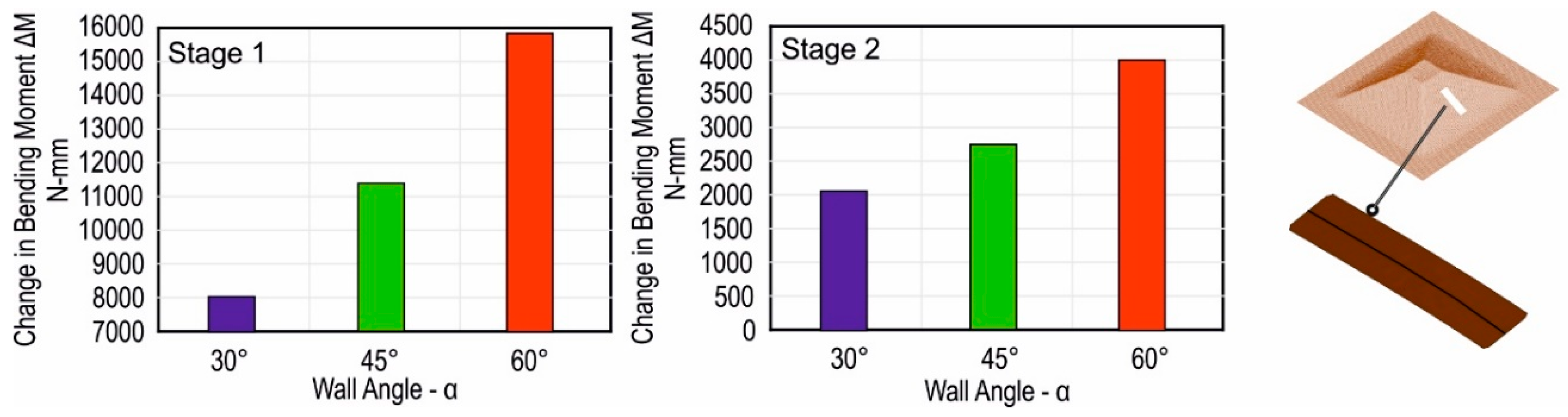
  • A significant change in the magnitude of the residual stress occurred upon trimming, and this was highest with the largest wall angle.
Further, the change in the bending moment occurring upon unclamping and trimming is presented in Figure 14. Important observation is as follows:
  • The change in the bending moment was highest with the largest wall angle, and this change is significant as compared to the other process parameters, i.e., tool diameter and wall angle.
It can be concluded that the highest change in the magnitude and the state of the residual stresses as well as the bending moment occurred with the largest wall angle. Hence, the largest geometric deviations, i.e., the largest curvature, should be with the largest wall angle. These observations are validated in the next section based on the curvature of the laser-cut strips from Section 2.2.

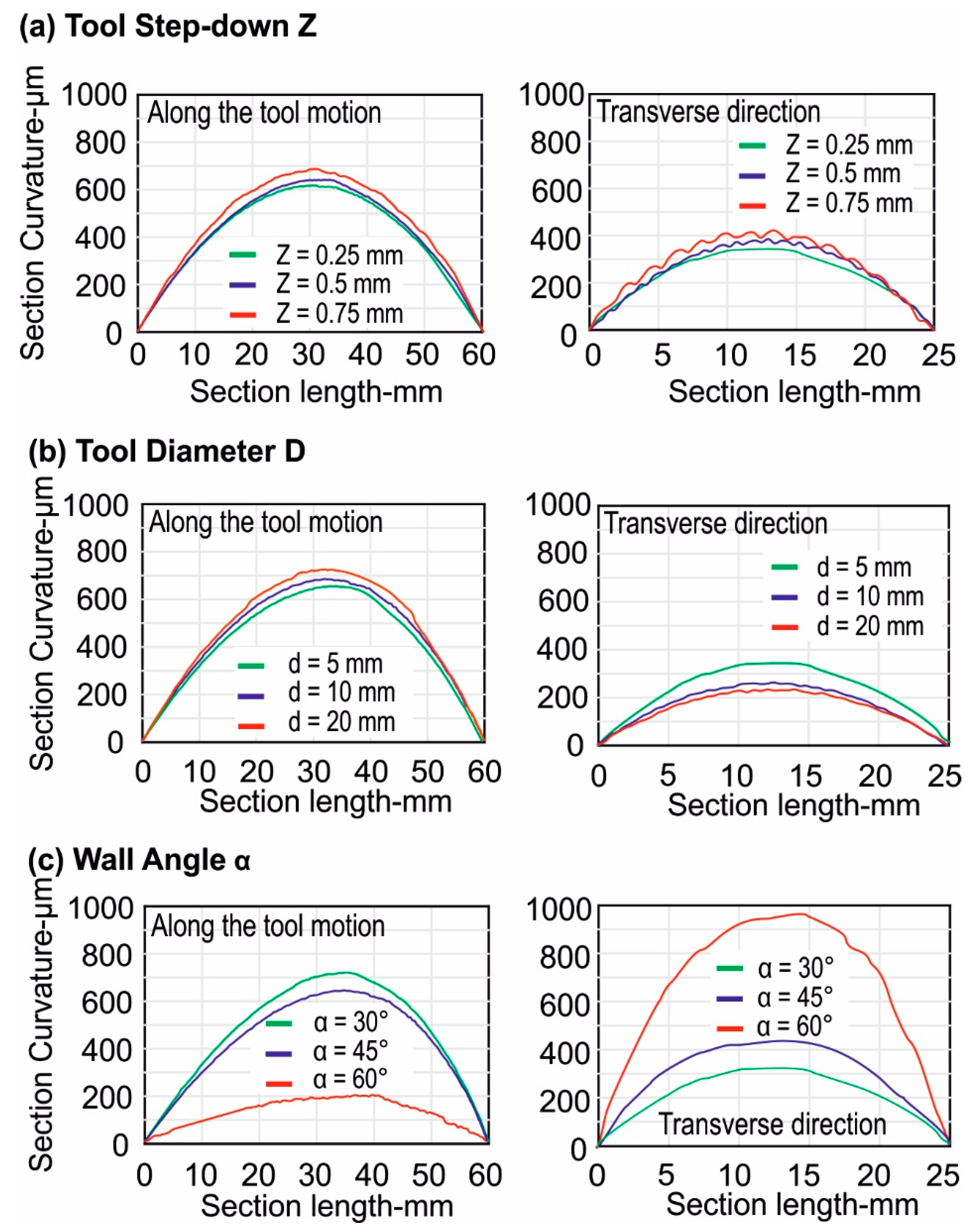
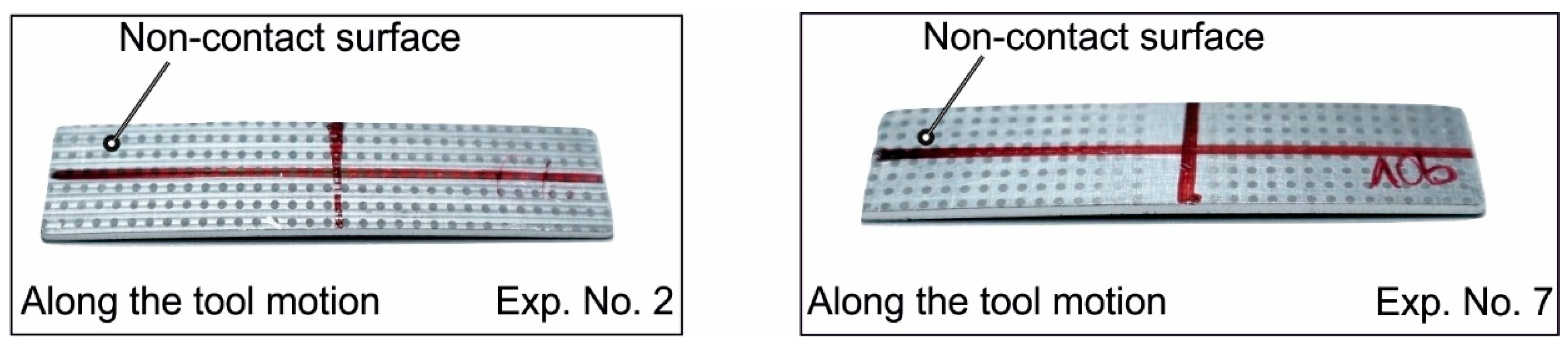
3.3. Residual Stresses vs. Geometrical Accuracy

According to Section 3.2, the largest change in the state of residual stresses and bending moment occurred with the largest tool step-down and tool diameters. This change was directly proportional to the contribution of the elastic deformation, which was recovered upon unclamping. Hence, this implies that the highest portion of the recovered elastic deformation was achieved with the largest tool diameter and tool step-down. This fact is experimentally validated by comparing the geometric profiles of the formed pyramids obtained after digitizing the pyramids (see Section 2.1) with the target geometry. The comparison of the geometric profiles is presented in Figure 15. The geometric deviations were largest with the greatest tool diameter and tool step-down.
Further, to investigate the effect of the residual stresses on the geometrical accuracy after trimming, the curvature of the experimentally cut strips was analyzed. A comparison of the strip curvatures is presented in Figure 16 along two directions, i.e., along and in the transverse direction of the tool motion. The curvatures of the strips are presented for tool diameters, tool step-down values, and wall angles. Based on the numerical analysis of the residual stresses (Section 3.2), the highest curvature should be obtained with the largest tool step-down due to the highest change in the residual stresses and bending moment. This is validated by the experimentally measured curvature of the strips. In both directions, i.e., along and in the transverse direction of the tool motion, the curvature of the strip increased by increasing the tool step-down (Figure 16a).
In the case of tool diameter, numerical analysis of the residual stresses indicates that the largest change in residual stresses and bending moments upon unclamping occurred with the largest tool diameter. This was validated by comparing the geometric profiles of the formed pyramids (Figure 15). In the case of trimming, numerical analysis (Figure 11 and Figure 12) indicates that the change in the residual stresses and bending moments was slightly greater with the smaller tool diameter. Experimentally measured curvatures for the changing tool diameters indicate different behavior in two directions of the tool motion. The curvature is highest with the largest tool diameter along the tool motion and highest with the smallest tool diameter in the transverse direction. This is because, upon trimming, the respective change in the magnitude of the bending moment was highest in the transverse direction with the smallest tool diameter (Figure 12). Hence, the curvature is highest with the smallest tool diameter. On the other hand, the change in the magnitude of the residual stress was not large enough along the direction of the tool motion, so the state of the geometric deviations upon unclamping was held further in the trimming state; i.e., the deviations were largest with the largest tool diameter. In comparison to unclamping, geometric deviations will further increase but respective differences in their magnitude for different tool diameters will reduce upon trimming.
The numerical analysis for tool step-down (Figure 9) and tool diameter (Figure 11) indicates that the state of the residual stresses in the clamped state, i.e., the tension and compression on the tool contact and non-contact side, changed to tension and compression on the non-contact and tool contact side, respectively, in the trimmed state. This implies that the stress state and the resulting bending moment caused the strips cut along and in the transverse direction of the tool motion to curve in such a way that they have a curvature toward the lower surface; i.e., the non-contact side will be under tension. The strips cut from the experimentally formed pyramids curl in the same way as predicted by numerical analysis. This is represented in Figure 17.
The curvature of the strips cut from pyramids exhibits different behavior for small and large wall angles as indicated by Figure 16. In case of changing wall angles, numerical analysis of the residual stresses (Figure 13) indicates that upon trimming the largest change in the residual stresses and bending moment was with the greatest wall angle, and the change in intensity was more severe in the transverse direction of the tool motion. In the transverse direction, even for a small strip, i.e., 30 × 17 mm, the curvature is larger than the strip cut along the tool motion (Figure 16). In fact, the change in the state of the residual stresses in the transverse direction caused the strips to curl in the opposite direction, i.e., toward the transverse direction, and this effect was highest with the greatest wall angle. This can be seen in Figure 18b and explains the lowest curvature along the tool motion direction with the largest wall angle and vice versa for the transverse direction.
The state of the residual stresses obtained with the larger wall angles was completely different as compared to the other process parameters. Initially, both the top and bottom faces were under tension with greater wall angles. In the trimmed state, the state of residual stresses changes to compression for both faces, which is opposite to the residual stress behavior exhibited by other process parameters, i.e., tool diameter and tool step-down. As a result, the final curvature of the strip cut from the pyramid with a 60° wall angle exhibits a curvature toward the opposite side as compared to the strip cut with the smaller wall angle (Figure 18a,c)
As the geometric deviation represented by the measured curvature of the strips (Figure 16) also contain the geometric deviations upon unclamping and trimming, therefore to only determine the geometric deviation that occurred upon trimming, respective springback simulations of the strips cut along both directions of the tool motion from the springback model of the pyramids were performed (Figure 19). The results indicate that the previous findings (Section 3.2 and Section 3.3) hold true. The results are presented for three different cases. In the case of tool step-down, as indicated earlier, the highest geometric deviations that occurred upon trimming were with the greatest tool step-down value (Figure 19a). Further, the finding that the deviations in the transverse direction are highest with the smallest tool diameter is verified. As indicated in Figure 19b, the highest deviation in the transverse direction upon trimming was with the smallest tool diameter. Further, the geometric deviation, especially in the transverse direction, upon trimming was highest with the greatest wall angle (Figure 19c).
The experimental and numerical analysis indicates that it is necessary to take into consideration the development of the residual stresses throughout the entire process. It has been observed that the nature of the residual stresses can completely differ from the previous stage—for example, a completely different stress state in clamped and trimmed stage. Similarly, a very high dependence of the residual stresses on the selected process parameters has been found. Until now, no study had been reported in the literature that analyses the residual stresses in the entire process, so these previous observations from the literature hold only for a particular set of process parameters and for only one forming stage: the unclamping or the trimming stage.
The results presented in Section 3.2 and Section 3.3 help us to develop a more complete understanding of the residual stresses for the entire SPIF process and indicate that changing the equilibrium state of the part, i.e., unclamping or trimming, is followed by a significant change in residual stresses and bending moment. Important question that further arises is of how the developed knowledge can assist in improving geometrical accuracy. In this regard, three main process parameters, i.e., tool diameter, tool step-down, and wall angle, along with the three process stages, i.e., clamped, unclamped, and trimmed states of the SPIF process, were analyzed. Results indicate that, if the unclamped state is the final geometry and no trimming is to be carried out, then a smaller tool diameter, tool step-down, and wall angle increase the geometrical accuracy of the part. This is because the change in the magnitude of the residual stresses between clamped and unclamped states is smallest for these process parameters. In the case of subsequent trimming after unclamping, geometric deviation is severe in the transversal direction of the tool motion compared to the horizontal direction, and the geometric deviations are higher with a smaller tool diameter and a greater tool step-down and wall angle. Hence, it is recommended that a final part shape and a tool path be designed in such a way that the final shape of the part is obtained by trimming along the horizontal direction of the tool motion. In any case, to produce incrementally formed parts within desired tolerances, stress relief annealing in the clamped state is recommended [29].

4. Conclusions

In the present study, using optical forming analysis and residual stress measurements employing the hole-drilling method, a numerical model of the SPIF is validated. Using the validated numerical model, the residual stress state at various stages of the SPIF process is investigated. The numerical results are further co-related to the experimental data. A complete picture of the distribution of the residual stresses under varying process parameter is presented. Important conclusions are as follows:
(1)
The magnitude of the residual stresses in the clamped state increased when the tool diameter, tool step-down, and the wall angle increased. Upon unclamping, the respective change in the magnitude of the residual stresses and the bending moments was highest with the greatest tool-diameter and tool step-down. Upon trimming, the change in the magnitude of the residual stresses and bending moments was greatest with the highest tool step-down value. However, the change in the magnitude of the residual stresses and bending moment was highest with the smallest tool diameter in the transverse direction of the tool motion. Moreover, for greater wall angles, the respective change in the magnitude of residual stresses and bending moment was highest and occurred significantly in the transverse direction of the tool motion.
(2)
The widely known fact from the literature that a smaller tool step-down and a smaller tool diameter have a positive effect on geometrical accuracy is explained in terms of residual stress. This is because, during unclamping, the greatest changes in the magnitude of the residual stresses occurred with the greatest tool step-down and tool diameter. During unclamping, these changes in the magnitude of the residual stresses were directly proportional to the elastic portion of the deformation. The elastic portion of the deformation, which was recovered upon unclamping, increased when the tool step-down and tool diameter increased. Hence, geometrical accuracy in the unclamped state increases when tool step-down and tool diameter decrease.
(3)
However, upon trimming, the largest changes in the magnitude of the residual stresses occurred with the smallest tool diameter was significant in the transverse direction of the tool motion. Hence, geometric deviations were largest with the smallest tool diameter in the trimmed state.
(4)
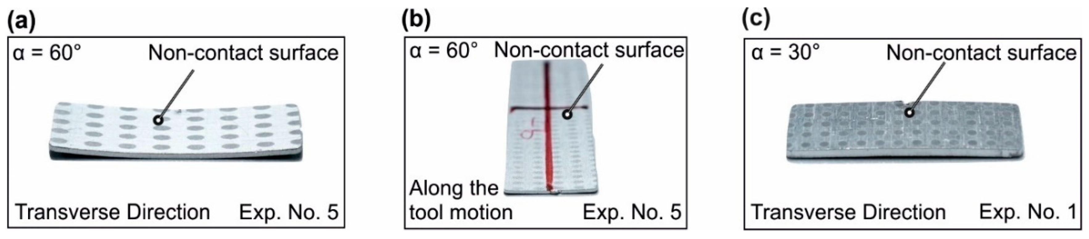
In contrast to tool diameter and tool step-down, the state of the residual stresses in the trimmed state with the greater wall angles was such that it caused the strips to curl toward the tool contact face, opposite to other process parameters.
(5)
The most significant parameter for the effect on the residual stresses and geometrical accuracy is the wall angle. The geometrical accuracy decreased significantly in the transverse direction when the wall angle was increased. However, this parameter is usually fixed, and its value depends on the geometry of the part to be formed. The other two parameters, i.e., tool diameter and tool step-down, also have a considerable effect on residual stress and geometrical accuracy.
(6)
The effect of changing process parameters on the residual stresses was more evident in the transverse direction of the tool motion.

Author Contributions

F.M. performed the experiments, numerical simulations and wrote the manuscript. M.B. conceptualized the work and edited the manuscript.

Funding

The manufacturing of the pyramids was done as part of the project ‘BA-4253/3-1’. The development of the model for cyclic plasticity, the residual stress analysis and the validation of the model were performed as part of project No. ‘BA 4253/6-1’ within the DFG priority program 2013.

Acknowledgement

The authors thank the German Research foundation (DFG) for the financial support of the projects.

Conflicts of Interest

The authors declare no conflict of interest.

References

  1. Jeswiet, J.; Micari, F.; Hirt, G.; Bramley, A.; Duflou, J.; Allwood, J. Asymmetric Single Point Incremental Forming of Sheet Metal. CIRP Ann. 2005, 54, 88–114. [Google Scholar] [CrossRef]
  2. Emmens, W.; Boogaard, A.V.D.; Boogaard, T.V.D. An overview of stabilizing deformation mechanisms in incremental sheet forming. J. Mater. Process. Technol. 2009, 209, 3688–3695. [Google Scholar] [CrossRef] [Green Version]
  3. Bambach, M.; Araghi, B.T.; Hirt, G. Strategies to improve the geometric accuracy in asymmetric single point incremental forming. Prod. Eng. 2009, 3, 145–156. [Google Scholar] [CrossRef]
  4. Allwood, J.M.; King, G.P.F.; Duflou, J.; Allwood, J. A structured search for applications of the incremental sheet-forming process by product segmentation. Proc. Inst. Mech. Eng. B J. Eng. Manuf. 2005, 219, 239–244. [Google Scholar] [CrossRef]
  5. Totten, G.E. Handbook of Residual Stress and Deformation of Steel; ASM International: Almere, The Netherlands, 2002. [Google Scholar]
  6. Holweger, W.; Walther, F.; Loos, J.; Wolf, M.; Schreiber, J.; Dreher, W.; Kern, N.; Lutz, S. Non-destructive subsurface damage monitoring in bearings failure mode using fractal dimension analysis. Ind. Lubr. Tribol. 2012, 64, 132–137. [Google Scholar] [CrossRef]
  7. Huber, N.; Heerens, J. On the effect of a general residual stress state on indentation and hardness testing. Acta Mater. 2008, 56, 6205–6213. [Google Scholar] [CrossRef] [Green Version]
  8. Kim, S.-J.; Kim, D.; Lee, K.; Cho, H.-H.; Han, H.N. Residual-stress-induced grain growth of twinned grains and its effect on formability of magnesium alloy sheet at room temperature. Mater. Charact. 2015, 109, 88–94. [Google Scholar] [CrossRef]
  9. Allwood, J.M.; Braun, D.; Music, O. The effect of partially cut-out blanks on geometric accuracy in incremental sheet forming. J. Mater. Process. Technol. 2010, 210, 1501–1510. [Google Scholar] [CrossRef]
  10. Tanaka, S.; Nakamura, T.; Hayakawa, K.; Motomura, K. Residual Stress in Sheet Metal Parts Made by Incremental Forming Process. AIP Conf. Proc. 2007, 908, 775–780. [Google Scholar]
  11. Radu, C.; Herghelegiu, E.; Tampu, N.C.; Cristea, I.; Tampu, C. The Residual Stress State Generated by Single Point Incremental Forming of Aluminum Metal Sheets. Appl. Mech. Mater. 2013, 371, 148–152. [Google Scholar] [CrossRef]
  12. Radu, C.; Tampu, C.; Cristea, I.; Chirita, B. The Effect of Residual Stresses on the Accuracy of Parts Processed by SPIF. Mater. Manuf. Process. 2013, 28, 572–576. [Google Scholar] [CrossRef]
  13. Jiménez, I.; López, C.; Martinez-Romero, O.; Mares, P.; Siller, H.R.; Diabb, J.; Sandoval-Robles, J.A.; Elías-Zúñiga, A. Investigation of residual stress distribution in single point incremental forming of aluminum parts by X-ray diffraction technique. Int. J. Adv. Manuf. Technol. 2017, 91, 2571–2580. [Google Scholar] [CrossRef]
  14. Singh, A.; Agrawal, A. Investigation of surface residual stress distribution in deformation machining process for aluminum alloy. J. Mater. Process. Technol. 2015, 225, 195–202. [Google Scholar] [CrossRef]
  15. Shi, X.; Hussain, G.; I Butt, S.; Song, F.; Huang, D.; Liu, Y. The state of residual stresses in the Cu/Steel bonded laminates after ISF deformation: An experimental analysis. J. Manuf. Process. 2017, 30, 14–26. [Google Scholar] [CrossRef]
  16. Behera, A.K.; Ou, H. Effect of stress relieving heat treatment on surface topography and dimensional accuracy of incrementally formed grade 1 titanium sheet parts. Int. J. Adv. Manuf. Technol. 2016, 87, 3233–3248. [Google Scholar] [CrossRef] [Green Version]
  17. Maqbool, F.; Bambach, M. Revealing the Dominant Forming Mechanism of Single Point Incremental Forming (SPIF) by Splitting Plastic Energy Dissipation. Procedia Eng. 2017, 183, 188–193. [Google Scholar] [CrossRef]
  18. Mohammadi, A.; Vanhove, H.; Van Bael, A.; Seefeldt, M.; Duflou, J.R. The effect of laser radiation on the residual stress levels of single point incrementally formed (SPIF) parts. In Proceedings of the International Workshop on Thermal Forming and Welding Distortion, Bremen, Germany, 9–10 April 2014. [Google Scholar]
  19. Ambrogio, G.; Cozza, V.; Filice, L.; Micari, F. An analytical model for improving precision in single point incremental forming. J. Mater. Process. Technol. 2007, 191, 92–95. [Google Scholar] [CrossRef]
  20. Micari, F.; Ambrogio, G.; Filice, L. Shape and dimensional accuracy in Single Point Incremental Forming: State of the art and future trends. J. Mater. Process. Technol. 2007, 191, 390–395. [Google Scholar] [CrossRef]
  21. Maeda, A.; Jin, Y.; Kuboki, T. Light press of sheet metal edge for reducing residual stress generated by laser cutting considering mechanical properties and intensity of residual stress. J. Mater. Process. Technol. 2015, 225, 178–184. [Google Scholar] [CrossRef] [Green Version]
  22. Rendler, N.J.; Vigness, I. Hole-drilling strain-gage method of measuring residual stresses. Exp. Mech. 1966, 6, 577–586. [Google Scholar] [CrossRef]
  23. Niku-Lari, A.; Flavenot, J.; Lu, J. Measurement of residual-stress distribution by the incremental hole-drilling method. J. Mech. Work. Technol. 1985, 11, 167–188. [Google Scholar] [CrossRef]
  24. Bambach, M.; Taleb-Araghi, B.; Hirt, G.; Reimers, W. Error control in explicit finite element simulation of incremental sheet metal forming. In Proceedings of the 7th International Conference and Workshop on 3D Sheet Metal Forming Processes (Numisheet2008), Interlaken, Switzerland, 1–5 September 2008. [Google Scholar]
  25. Chaboche, J.L.; Rousselier, G. On the Plastic and Viscoplastic Constitutive Equations—Part I: Rules Developed with Internal Variable Concept. J. Press. Vessel Technol. 1983, 105, 153–158. [Google Scholar] [CrossRef]
  26. Henrard, C.; Bouffioux, C.; Eyckens, P.; Sol, H.; Duflou, J.R.; Van Houtte, P.; Van Bael, A.; Duchêne, L.; Habraken, A.M. Forming forces in single point incremental forming: Prediction by finite element simulations, validation and sensitivity. Comput. Mech. 2010, 47, 573–590. [Google Scholar] [CrossRef]
  27. Bambach, M.; Hirt, G. Performance Assessment of Element Formulations and Constitutive Laws for the Simulation of Incremental Sheet Forming (ISF). Available online: http://citeseerx.ist.psu.edu/viewdoc/download?doi=10.1.1.485.6511&rep=rep1&type=pdf (accessed on 10 April 2019).
  28. Maqbool, F.; Bambach, M. Dominant deformation mechanisms in single point incremental forming (SPIF) and their effect on geometrical accuracy. Int. J. Mech. Sci. 2018, 136, 279–292. [Google Scholar] [CrossRef]
  29. Maqbool, F.; Bambach, M. A Modular Tooling Set-Up for Incremental Sheet Forming (ISF) with Subsequent Stress-Relief Annealing under Partial Constraints. In Proceedings of the AIP Conference, Dublin, Ireland, 26–28 April 2017. [Google Scholar]
Figure 1. Experimental set-up of the single point incremental forming (SPIF) process.
Jmmp 03 00031 g001
Figure 2. (a) Point pattern after incremental forming. (b) Major principle strain on the outer surface obtained by ARGUS®. (c) Geometry after forming obtained from ARGUS®.
Jmmp 03 00031 g002
Figure 3. Strips cut from the pyramids of different wall angles. (a) Along the tool motion and (b) in the transverse direction of the tool motion. (c) Geometry of the strip with curvature measured along Section 1 and Section 2. (d) Measurement of the curvature with a contour measurement machine.
Jmmp 03 00031 g003
Figure 4. Schematic of the hole-drilling method.
Jmmp 03 00031 g004
Figure 5. (a) Geometry of the tension-compression specimen. (b) Comparison of the stress–strain curves for optimal parameters.
Jmmp 03 00031 g005
Figure 6. A flow chart describing the procedure adopted to achieve the objectives of the study.
Jmmp 03 00031 g006
Figure 7. Comparison of the (a) major principle strains, (b) thickness reduction, and (c) formed geometries from the experiment and simulation for Experiment 1.
Jmmp 03 00031 g007
Figure 8. Comparison of the residual stresses along the tool motion direction, i.e., σ x at selected location for Experiments 1 and 6.
Jmmp 03 00031 g008
Figure 9. Distribution of the residual stresses in the center of the strip along and in the transverse direction of the tool motion for different tool step-down values (a) before unclamping, (b) after unclamping, and (c) after trimming.
Jmmp 03 00031 g009
Figure 10. Change in the bending moment for different tool step-down upon unclamping (Stage 1) and upon trimming (Stage 2) along a section.
Jmmp 03 00031 g010
Figure 11. Distribution of the residual stresses in the center of the strip along and in the transverse direction of the tool motion for different tool diameters: (a) before unclamping, (b) after unclamping, and (c) after trimming.
Jmmp 03 00031 g011
Figure 12. Change in the bending moment for different tool diameters upon unclamping (Stage 1) and upon trimming (Stage 2) along a section.
Jmmp 03 00031 g012
Figure 13. Distribution of the residual stresses in the center of the strip along and in the transverse direction of the tool motion for different wall angles: (a) before unclamping, (b) after unclamping, and (c) after trimming.
Jmmp 03 00031 g013
Figure 14. Change in the bending moment for different wall angles upon unclamping (Stage 1) and upon trimming (Stage 2) along a section.
Jmmp 03 00031 g014
Figure 15. Comparison of the geometric profile with the target geometry for (a) different tool diameters and (b) different tool step-down values.
Jmmp 03 00031 g015
Figure 16. Curvature of the strips cut along and in the transverse direction of tool motion for (a) tool step-down Z, (b) tool diameter D, and (c) wall angle α.
Jmmp 03 00031 g016
Figure 17. Curvature of the strips toward the lower surface. The contact side undergoes compression, and the non-contact side undergoes tension.
Jmmp 03 00031 g017
Figure 18. (a) Curvature of a strip for large wall angle in the transverse direction. (b) Curling of a strip cut along the tool motion toward the transverse direction for large wall angle. (c) Curvature of a strip for small wall angle in the transverse direction.
Jmmp 03 00031 g018
Figure 19. Curvature of the strip only due to the residual stresses upon trimming from numerical simulations for (a) three tool step-down values along the tool motion, (b) three tool diameters in the transverse direction, and (c) three wall angles along the transverse direction.
Jmmp 03 00031 g019
Table 1. Design of experiments (DoE).
Experiment No.Tool Diameter (D/mm)Wall Angle α Tool Step-Down (Z/mm)
1530°0.25
2530°0.5
3530°0.75
4545°0.25
5560°0.25
61030°0.25
72030°0.25

