Analysis of Geometrical Characteristics and Properties of Laser Cladding 85 wt.% Ti + 15 wt.% TiBCN Powder on 7075 Aluminum Alloy Substrate


Abstract
:1. Introduction
2. Materials and Methods
3. Results and Discussion
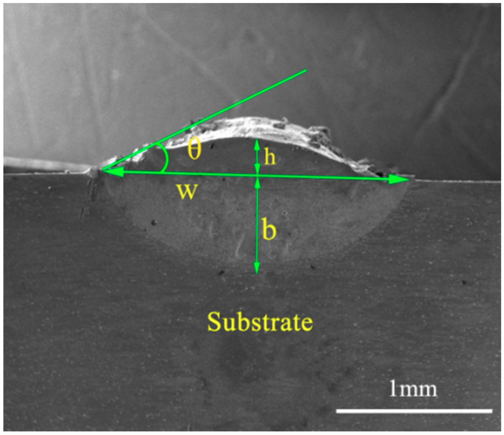
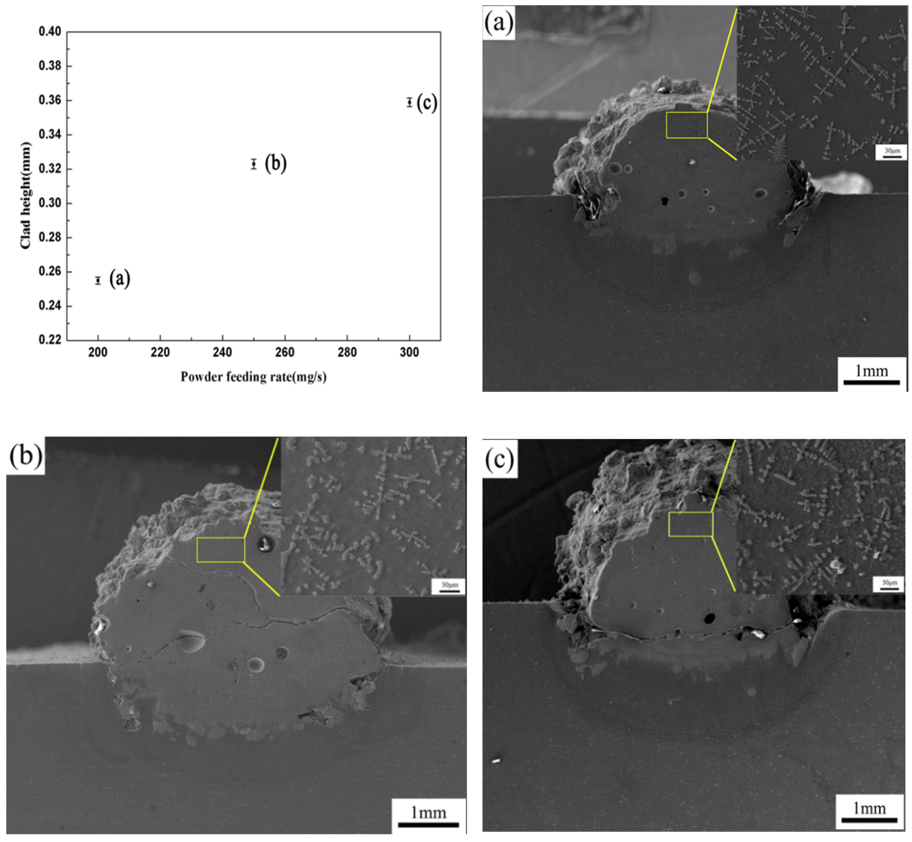
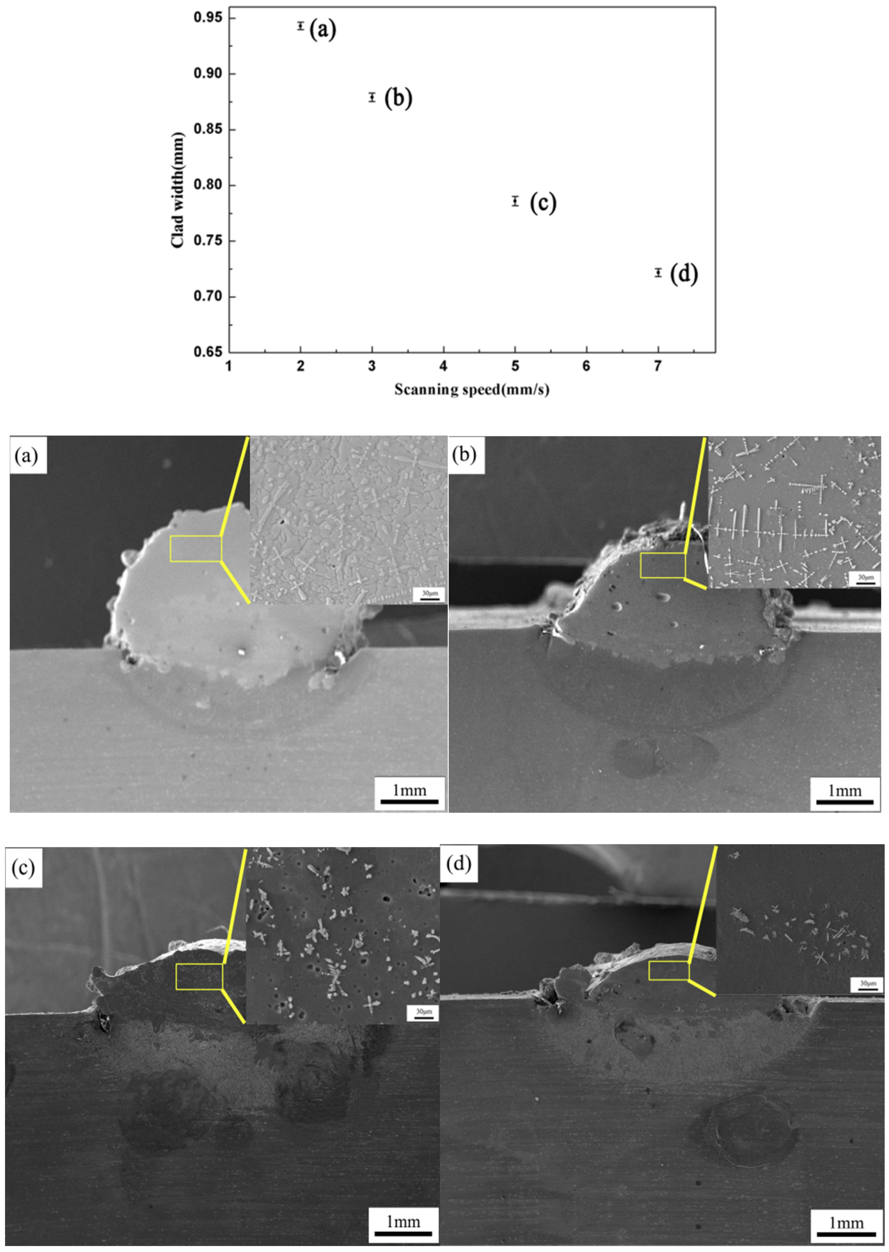
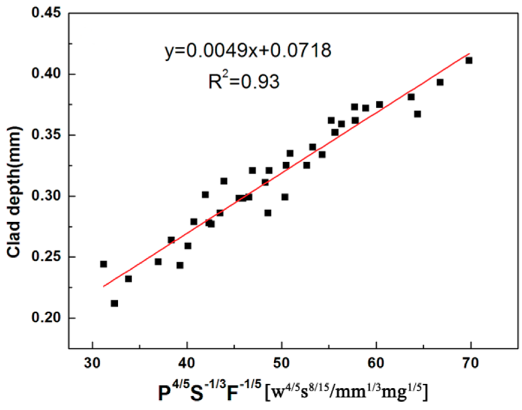
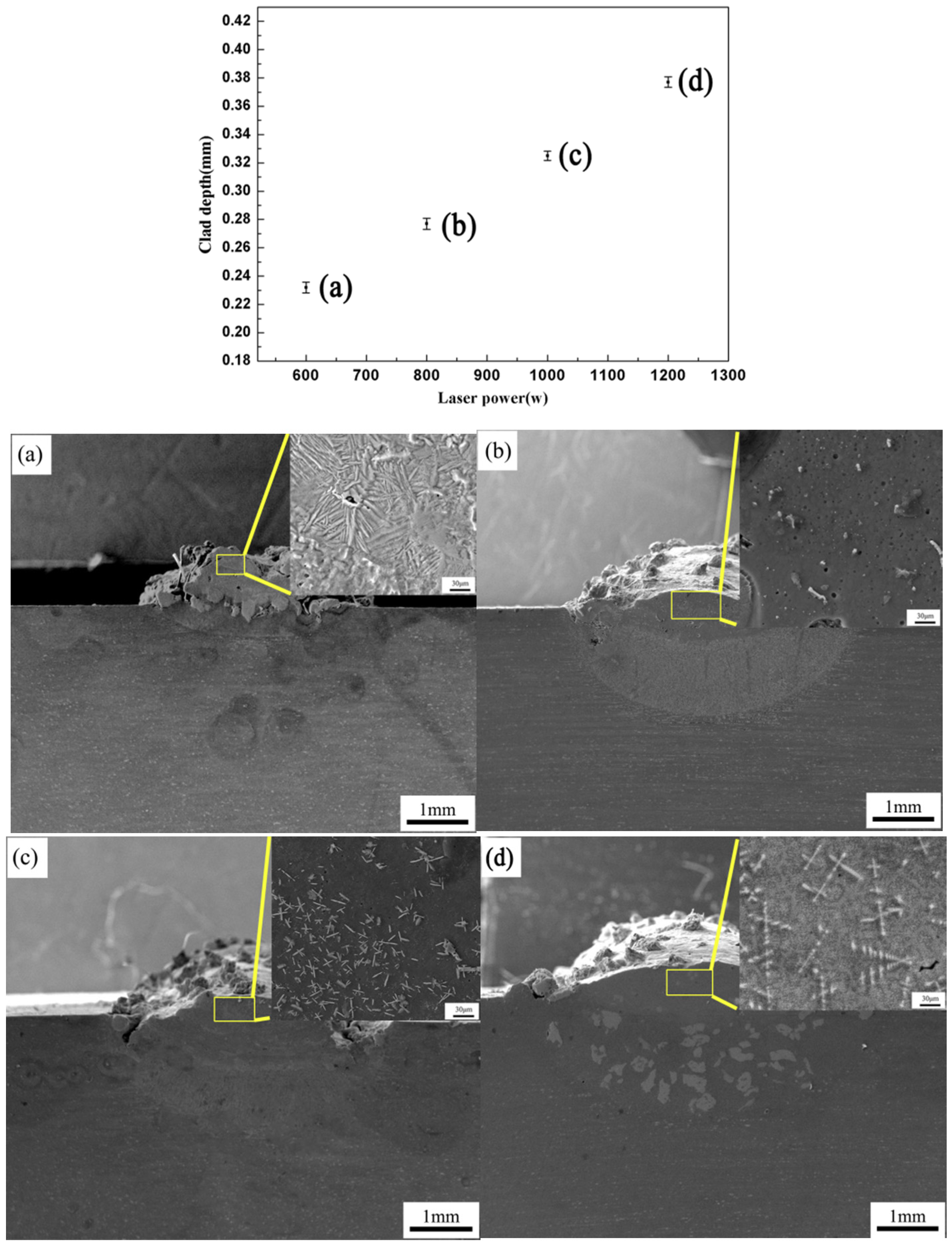
3.1. Geometrical Characteristics and Microstructure
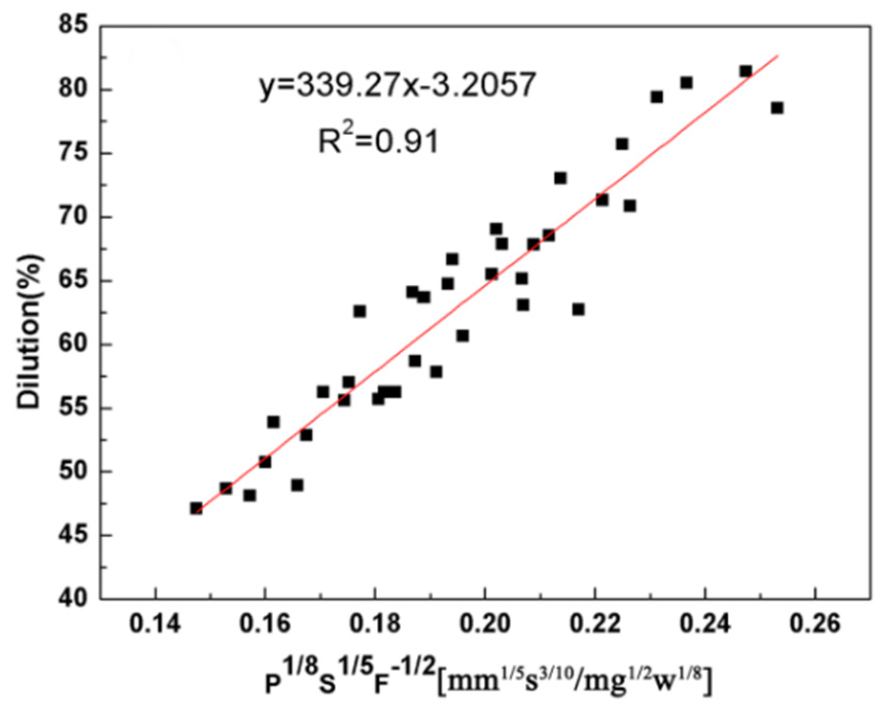
3.2. Properties
4. Conclusions
Author Contributions
Funding
Conflicts of Interest
References
- Peng, X.Y.; Chu, J.; Aldalbahi, A.; Rivera, M.; Wang, L.; Duan, S.; Feng, P. A flexible humidity sensor based on KC-MWCNTs composites. Appl. Surf. Sci. 2016, 387, 149–154. [Google Scholar] [CrossRef]
- Al-Asedy, H.J.; Bidin, N.; Al-khafaji, S.A.; Bakhtiar, H. Sol-gel grown aluminum/gallium co-doped ZnO nanostructures: Hydrogen gas sensing attributes. Mater. Sci. Semiconduct. Process. 2018, 77, 50–57. [Google Scholar] [CrossRef]
- Bobzin, K.; Brögelmann, T.; Kalscheuer, C.; Liang, T. High-rate deposition of thick (Cr, Al) on coatings by high speed physical vapor deposition. Surf. Coat. Technol. 2017, 322, 152–162. [Google Scholar] [CrossRef]
- Hou, G.; An, Y.; Zhao, X.; Zhou, H.; Chen, J.; Li, S.; Deng, W. Improving interfacial, mechanical and tribological properties of alumina coatings on Al alloy by plasma arc heat-treatment of substrate. Appl. Surf. Sci. 2017, 411, 53–66. [Google Scholar] [CrossRef]
- Li, Y.; Zhang, P.; Bai, P.; Wu, L.; Liu, B.; Zhao, Z. Microstructure and properties of Ti/TiBCN coating on 7075 aluminum alloy by laser cladding. Surf. Coat. Technol. 2018, 334, 142–149. [Google Scholar] [CrossRef]
- Lin, Y.; Lei, Y.; Li, X.; Zhi, X.; Fu, H. A study of TiB2/TiB gradient coating by laser cladding on titanium alloy. Opt. Laser Eng. 2016, 82, 48–55. [Google Scholar] [CrossRef]
- De Oliveira, U.; Ocelik, V.; De Hosson, J.T.M. Analysis of coaxial laser cladding processing conditions. Surf. Coat. Technol. 2005, 197, 127–136. [Google Scholar] [CrossRef]
- Barekat, M.; Razavi, R.S.; Ghasemi, A. Nd: YAG laser cladding of Co-Cr-Mo alloy on γ-TiAl substrate. Opt. Laser Technol. 2016, 80, 145–152. [Google Scholar] [CrossRef]
- Erfanmanesh, M.; Abdollah-Pour, H.; Mohammadian-Semnani, H.; Shoja-Razavi, R. An empirical-statistical model for laser cladding of WC-12Co powder on AISI 321 stainless steel. Opt. Laser Technol. 2017, 97, 180–186. [Google Scholar] [CrossRef]
- Ocelík, V.; De Oliveira, U.; De Boer, M.; De Hosson, J.T.M. Thick Co-based coating on cast iron by side laser cladding: Analysis of processing conditions and coating properties. Surf. Coat. Technol. 2007, 201, 5875–5883. [Google Scholar] [CrossRef] [Green Version]
- Riveiro, A.; Mejías, A.; Lusquiños, F.; Del Val, J.; Comesaña, R.; Pardo, J.; Pou, J. Laser cladding of aluminum on AISI 304 stainless steel with high-power diode lasers. Surf. Coat. Technol. 2014, 253, 214–220. [Google Scholar] [CrossRef]
- El Cheikh, H.; Courant, B.; Branchu, S.; Hascoet, J.Y.; Guillén, R. Analysis and prediction of single laser tracks geometrical characteristics in coaxial laser cladding process. Opt. Lasers Eng. 2012, 50, 413–422. [Google Scholar] [CrossRef] [Green Version]
- Ansari, M.; Razavi, R.S.; Barekat, M. An empirical-statistical model for coaxial laser cladding of NiCrAlY powder on Inconel 738 superalloy. Opt. Lasers Eng. 2016, 86, 136–144. [Google Scholar] [CrossRef]
- Rashid, R.R.; Abaspour, S.; Palanisamy, S.; Matthews, N.; Dargusch, M.S. Metallurgical and geometrical characterisation of the 316L stainless steel clad deposited on a mild steel substrate. Surf. Coat. Technol. 2017, 327, 174–184. [Google Scholar] [CrossRef]
- Nazari, K.A.; Rashid, R.R.; Palanisamy, S.; Xia, K.; Dargusch, M.S. A novel Ti-Fe composite coating deposited using laser cladding of low cost recycled nano-crystalline titanium powder. Mater. Lett. 2018, 229, 301–304. [Google Scholar] [CrossRef]
- Zhuang, W.; Liu, Q.; Djugum, R.; Sharp, P.K.; Paradowska, A. Deep surface rolling for fatigue life enhancement of laser clad aircraft aluminum alloy. Appl. Surf. Sci. 2014, 320, 558–562. [Google Scholar] [CrossRef]
- Klingenberg, M.L.; Naguy, D.A.; Naguy, T.A.; Straw, R.J.; Joseph, C.; Mongelli, G.A.; Arthur, J.J. Transitioning laser technology to support air force depot transformation needs. Surf. Coat. Technol. 2007, 202, 45–57. [Google Scholar] [CrossRef]
- Chi, Y.; Gu, G.; Yu, H.; Chen, C. Laser surface alloying on aluminum and its alloys: A review. Opt. Lasers Eng. 2018, 100, 23–37. [Google Scholar] [CrossRef]
- Yue, T.M.; Huang, K.J.; Man, H.C. In situ laser cladding of Al2O3 bearing coatings on aluminium alloy 7075 for improvement of wear resistance. Surf. Eng. 2007, 23, 142–146. [Google Scholar] [CrossRef]
- Van Acker, K.; Vercammen, K. Abrasive wear by TiO2 particles on hard and on low friction coatings. Wear 2004, 256, 353–361. [Google Scholar] [CrossRef]
- Zhao, Z.Y.; Guan, R.G.; Zhang, J.H.; Zhao, Z.Y.; Bai, P.K. Effects of Process Parameters of Semisolid Stirring on Microstructure of Mg-3Sn-1Mn-3SiC (wt %) Strip Processed by Rheo-rolling. Acta Metal. Sin. 2017, 30, 66–72. [Google Scholar] [CrossRef]
- Zhong, D.; Sutter, E.; Moore, J.J.; Mustoe, G.G.W.; Levashov, E.A.; Disam, J. Mechanical properties of Ti-B-C-N coatings deposited by magnetron sputtering. Thin Solid Films 2001, 398, 320–325. [Google Scholar] [CrossRef]
- Hu, J.; Dong, X.; Tosto, S. Microstructure of Face Centered Cubic (fcc) TiB Powder Synthesized by Boronizing of Ti Powder. J. Am. Ceram. Soc. 2012, 95, 2089–2092. [Google Scholar] [CrossRef]
- Tsai, P.C.; Chen, W.J.; Chen, J.H.; Chang, C.L. Deposition and characterization of TiBCN films by cathodic arc plasma evaporation. Thin Solid Films 2009, 517, 5044–5049. [Google Scholar] [CrossRef]
- Lin, J.; Moore, J.J.; Mishra, B.; Pinkas, M.; Sproul, W.D. The structure and mechanical and tribological properties of TiBCN nanocomposite coatings. Acta Mater. 2010, 58, 1554–1564. [Google Scholar] [CrossRef]
- Sun, Y.; Hao, M. Statistical analysis and optimization of process parameters in Ti6Al4V laser cladding using Nd:YAG laser. Opt. Lasers Eng. 2012, 50, 985–995. [Google Scholar] [CrossRef]
- Tan, H.; Luo, Z.; Li, Y.; Yan, F.; Duan, R. Microstructure and wear resistance of Al2O3-M7C3/Fe composite coatings produced by laser controlled reactive synthesis. Opt. Laser Technol. 2015, 68, 11–17. [Google Scholar] [CrossRef]
- Duan, X.; Gao, S.; Dong, Q.; Zhou, Y.; Xi, M.; Xian, X.; Wang, B. Reinforcement mechanism and wear resistance of Al2O3/Fe-Cr-Mo steel composite coating produced by laser cladding. Surf. Coat. Technol. 2016, 291, 230–238. [Google Scholar] [CrossRef]
- Guo, Y.; Zhang, Y.; Li, Z.; Wei, S.; Zhang, T.; Yang, L.; Liu, S. Microstructure and properties of in-situ synthesized ZrC-Al3Zr reinforced composite coating on AZ91D magnesium alloy by laser cladding. Surf. Coat. Technol. 2018, 334, 471–478. [Google Scholar] [CrossRef]


| Material | Si | Fe | Cu | Mn | Mg | Cr | Zn | Ti | Al | Others |
|---|---|---|---|---|---|---|---|---|---|---|
| 7075 Al alloy | 0.4 | 0.5 | 1.2–2.0 | 0.30 | 2.1–2.9 | 0.18–0.28 | 5.1–6.1 | 0.2 | Bal | <0.05 |
| Processing Parameter | Value |
|---|---|
| Laser power (W) | 600–1200 |
| Scanning speed (mm/s) | 2–7 |
| Powder feeding rate (mg/s) | 200–300 |
| Processing gas Ar shielding gas flow rate (L/min) | 2.5 |
| Powder carrier gas flow rate (L/min) | 10 |
| Overlap rate | 30% |
| Quantity (y) | Combined Paramerer (x) | R | A | B |
|---|---|---|---|---|
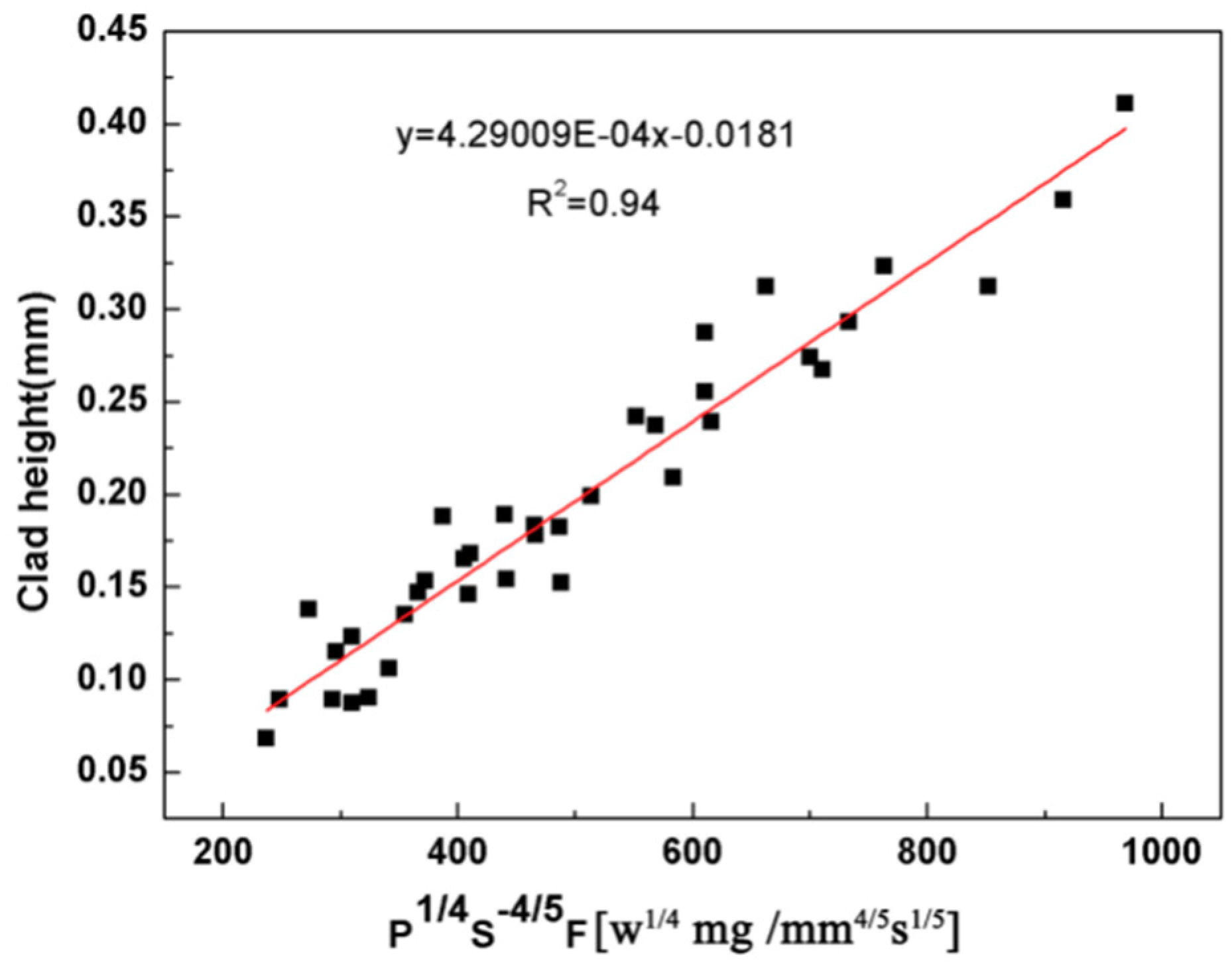
| h (mm) | P1/4S−4/5F (w1/4 mg /mm4/5s1/5) | 0.97 | 4.29009 × 10⁻⁴ | −0.0181 |
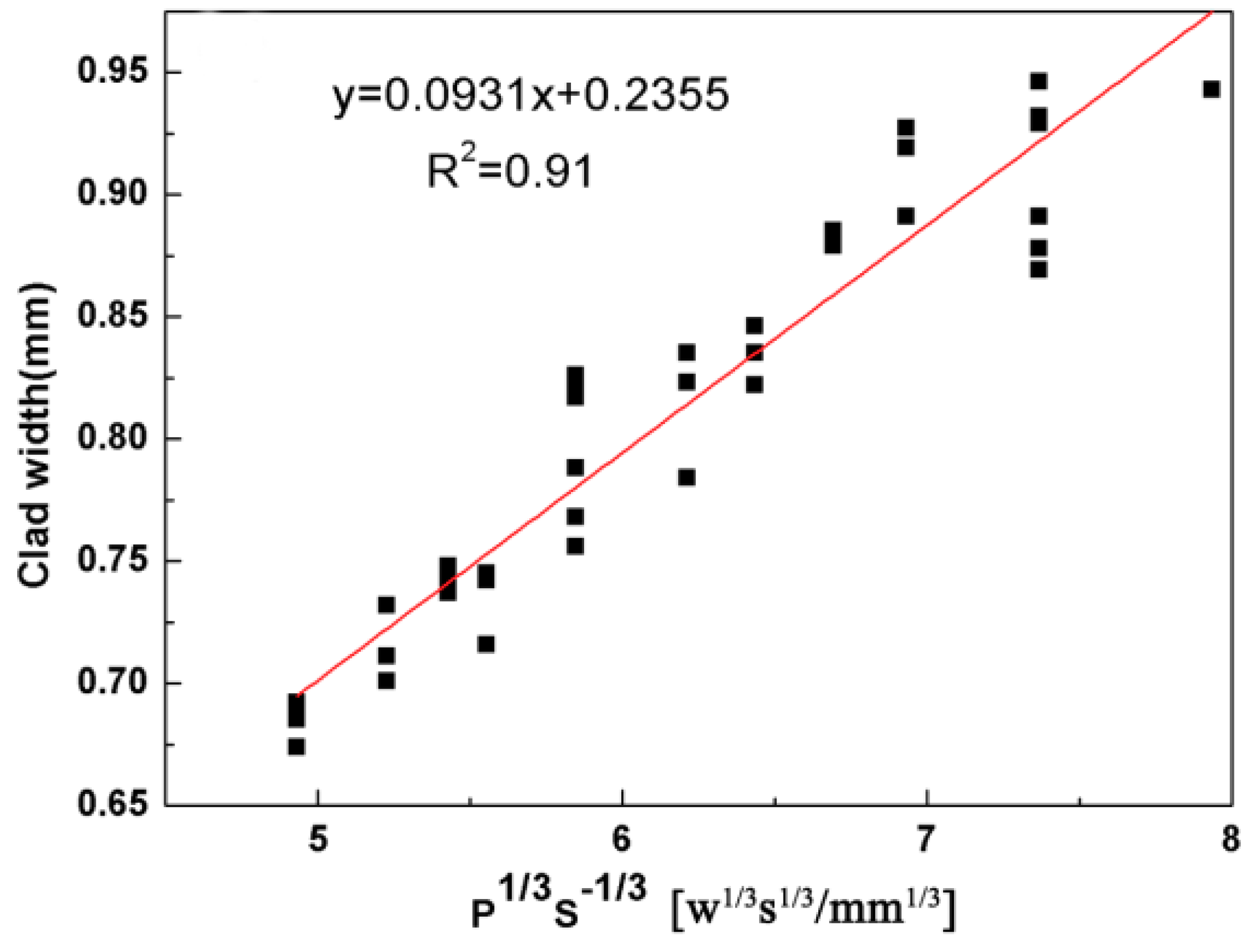
| w (mm) | P1/3S−1/3 (w1/3 s1/3 /mm1/3) | 0.95 | 0.0931 | 0.2355 |
| b (mm) | P4/5S−1/3F−1/5 (w4/5s8/15/mm1/3mg1/5) | 0.96 | 0.0049 | 0.0718 |
| D (%) | P−1/8S1/5F−1/2 (mm1/5s3/10/mg1/2w1/8) | 0.95 | 339.27 | −3.2057 |
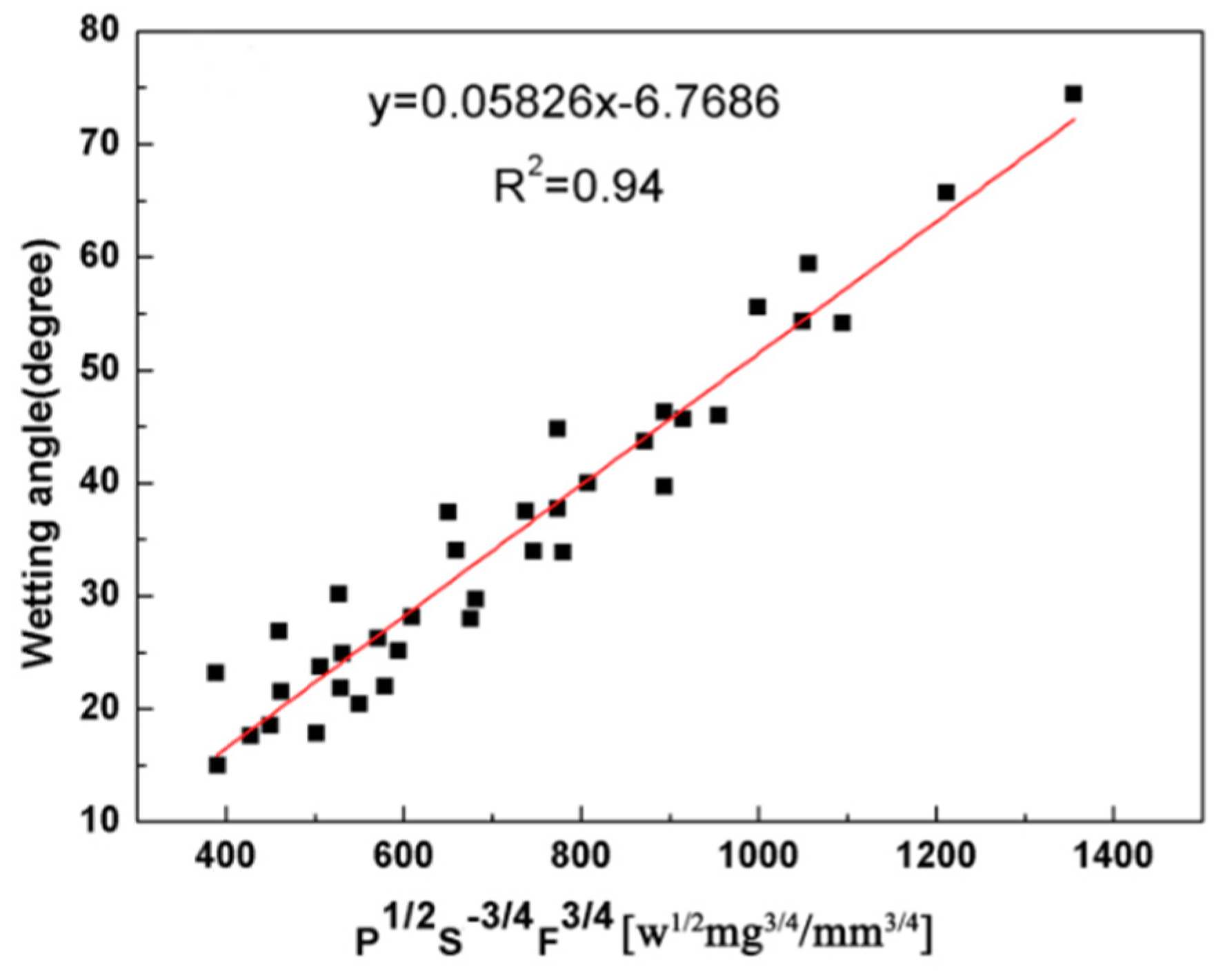
| θ (degree) | P1/2S−3/4F3/4 (w1/2 mg3/4/mm3/4) | 0.96 | 0.05826 | −6.7686 |
© 2018 by the authors. Licensee MDPI, Basel, Switzerland. This article is an open access article distributed under the terms and conditions of the Creative Commons Attribution (CC BY) license (http://creativecommons.org/licenses/by/4.0/).
Share and Cite
Li, Y.-X.; Zhang, P.-F.; Bai, P.-K.; Zhao, Z.-Y.; Liu, B. Analysis of Geometrical Characteristics and Properties of Laser Cladding 85 wt.% Ti + 15 wt.% TiBCN Powder on 7075 Aluminum Alloy Substrate. Materials 2018, 11, 1551. https://doi.org/10.3390/ma11091551
Li Y-X, Zhang P-F, Bai P-K, Zhao Z-Y, Liu B. Analysis of Geometrical Characteristics and Properties of Laser Cladding 85 wt.% Ti + 15 wt.% TiBCN Powder on 7075 Aluminum Alloy Substrate. Materials. 2018; 11(9):1551. https://doi.org/10.3390/ma11091551
Chicago/Turabian StyleLi, Yu-Xin, Peng-Fei Zhang, Pei-Kang Bai, Zhan-Yong Zhao, and Bin Liu. 2018. "Analysis of Geometrical Characteristics and Properties of Laser Cladding 85 wt.% Ti + 15 wt.% TiBCN Powder on 7075 Aluminum Alloy Substrate" Materials 11, no. 9: 1551. https://doi.org/10.3390/ma11091551