Glassy Carbon: A Promising Material for Micro- and Nanomanufacturing


Karlsruhe Institute of Technology, Institute of Microstructure Technology, Hermann-von-Helmholtz-Platz 1, 76334 Eggenstein-Leopoldshafen, Germany
Materials 2018, 11(10), 1857; https://doi.org/10.3390/ma11101857
Submission received: 20 August 2018
/
Revised: 13 September 2018
/
Accepted: 18 September 2018
/
Published: 28 September 2018
(This article belongs to the Special Issue Glassy Carbon: Microstructure, Properties and Applications)
Abstract
:When certain polymers are heat-treated beyond their degradation temperature in the absence of oxygen, they pass through a semi-solid phase, followed by the loss of heteroatoms and the formation of a solid carbon material composed of a three-dimensional graphenic network, known as glassy (or glass-like) carbon. The thermochemical decomposition of polymers, or generally of any organic material, is defined as pyrolysis. Glassy carbon is used in various large-scale industrial applications and has proven its versatility in miniaturized devices. In this article, micro and nano-scale glassy carbon devices manufactured by (i) pyrolysis of specialized pre-patterned polymers and (ii) direct machining or etching of glassy carbon, with their respective applications, are reviewed. The prospects of the use of glassy carbon in the next-generation devices based on the material’s history and development, distinct features compared to other elemental carbon forms, and some large-scale processes that paved the way to the state-of-the-art, are evaluated. Selected support techniques such as the methods used for surface modification, and major characterization tools are briefly discussed. Barring historical aspects, this review mainly covers the advances in glassy carbon device research from the last five years (2013–2018). The goal is to provide a common platform to carbon material scientists, micro/nanomanufacturing experts, and microsystem engineers to stimulate glassy carbon device research.
1. Introduction
Carbon has undoubtedly dominated the material science and engineering research in the last two decades. Among various carbon forms, graphene and its derivatives are the most extensively studied materials, which have resulted in nearly 200000 publications since 1995 [1]. Some synthetic carbon forms (i.e., obtained by a bottom-up manufacturing approach), such as fullerenes, offer intriguing scientific questions, for example, related to the rehybridization of the π-atomic orbital [2,3]. Others, such as graphene flakes and carbon nanotubes (CNTs), have attracted considerable attention towards their usability in micro and nano devices [4,5]. The most common, scalable approach for fabricating graphene and CNT-based devices involves mixing these materials (in bulk) with a binder or glue, followed by patterning the thus obtained ‘inks’ onto suitable substrates [6,7]. These fabrication techniques are scalable, but are limited to two-dimensional geometries. The desirable characteristic properties of the individual nanocarbon units are often compromised due to their interaction with the binder [8]. Moreover, handling carbon nanomaterials in powder form is challenging due to their extremely light weight and a lack of safety data on the potential health hazards [9].
A different, top-down manufacturing approach for fabricating graphene-rich carbon devices is to pattern a polymer using widespread lithographic techniques, and carbonize these structures using the pyrolysis process [10,11]. In the last two decades, a variety of microfabrication techniques that utilize radiation-induced lithography have been developed for polymer patterning in the micro/nano scale. Notable examples include photolithography [12], two-photon lithography [13,14], nanoimprint lithography [15,16], X-ray lithography [17], and their combinations. These techniques typically entail a patternable polymer (resist) that can be spin-coated or drop-casted onto a suitable substrate (e.g., silicon wafer) and baked to yield a dry film, which is well below its glass-transition temperature (Tg) at the time of the radiation exposure.
Phenol-formaldehyde (PF) resins, which are well-known glassy carbon precursors, are optimum as resist materials, owing to their thermosetting character, availability in various viscosities, and the possibility of incorporating epoxy side groups that facilitate a chemical amplification after the photoacid generation [18,19]. Consequently, several commercially available photoresists, such as SU-8, AZ resists, mr-NIL resists (tradenames) are primarily composed these resins. Other resists include acrylate-based polymers [20,21] and various inorganic materials [22,23,24], and may entail further optimization when used in the nano-scale fabrication [13,15]. Some of these resists would yield none, or extremely small quantities of carbon on pyrolysis, which may have significantly different properties compared to glassy carbon. Even in the case of a known glassy carbon precursor, a detailed evaluation of the material properties prior to device fabrication is essential, since the actual microstructure of the resulting carbon is influenced by various manufacturing and pyrolysis conditions [25,26,27]. Notably, the exact chemical composition of the commercial resists is often patent-bound; only the elementary chemical unit is disclosed, which provides the first cues on the possibility of its carbonization and the nature of the resulting carbon, but may not be sufficient for a complete assessment of the carbonization mechanism. The focus of this article is glassy carbon-based devices, therefore, only those resists that yield this material are of interest.
In addition to the carbonization of patterned polymers, device-compatible micro/nano structures can be realized by directly machining glassy carbon. Although this material is difficult to machine, methods, such as electrochemical [28] and thermochemical [29] etching, Focused Ion Beam (FIB) milling [30], and laser machining [31] have been employed to pattern it. In this contribution, some recent glassy carbon micro/nano devices fabricated using both strategies are described. Physicochemical properties of nano-scale glassy carbon where the structure size plays a vital role, and thus renders it dissimilar to the bulk manufactured material, are detailed. An attempt is made to classify all polymer-derived carbons, and correctly place glassy carbon among them. Concerns that have experienced competing views from researchers and are still open for discussion, for example, related to the purity of the low-temperature glassy carbon at the nano-scale, as well as and some nomenclature issues, are evaluated. Prior to indulging into the current research on glassy carbon, a brief history of the development of pyrolytic carbons and their early applications is presented below.
2. Brief History of Pyrolytic Carbons
In the early 20th century, graphite became a preferred substitute for metals in various applications, such as battery electrodes and lightweight aircraft parts. Graphite was also widely used as the moderator in the nuclear reactors, and as a high-temperature resistant manufacturing material in the space vehicles (e.g., rocket nozzles, nose shields [32]). This increasing commercial demand motivated the research on artificial graphite and graphite-like materials, which could be produced in large quantities and featured a relatively high purity. As a result, thermal treatment of various organic materials, and the properties of the resulting carbon were extensively studied in the early- and mid-20th century [32,33]. These carbon materials were designated ‘pyrolytic carbon’ or ‘pyrolytic graphite’. It was soon established that the carbon obtained from different precursors had measureable differences in terms of both microstructure and properties. Some were similar to polycrystalline graphite (ABABA type crystal structure), while others featured randomly oriented small graphitic crystallites with a larger interlayer separation and misaligned basal planes, and could not be converted into graphite, even at very high temperatures. These were called non-graphitizing carbons [34] (details in Section 4.2), and were primarily studied using X-ray diffraction (XRD) techniques during their early development [35,36]. Glassy carbon belongs to this category, which is methodically explained in Section 4.
3. Pyrolysis
The term pyrolysis is not limited to the heat-treatment of polymers, it defines the thermochemical decomposition of any organic precursor, including gaseous hydrocarbons (e.g., acetylene [32,37,38]), hydrocarbon-rich oils [39] and various petroleum byproducts [40]. Gas-phase pyrolysis (i.e., thermal cracking of hydrocarbons [41,42]) followed by carbon deposition is generally referred to as the Chemical Vapor Deposition (CVD) of carbonaceous materials in the contemporary literature [43]. Another well-known application of pyrolysis is in the treatment of waste polymers (both synthetic and natural) for biofuel [1,44,45], and biogas [46] production. Here, the heat treatment temperatures can be below 900 °C, and occasionally the environment may even contain oxygen [47,48], depending on what is expected as the end-product. Pyrolysis is also used in the context of metallurgy (e.g., in pyrometallurgy [49]), where the desirable end-product is usually not carbon [50]. In this article, only the pyrolysis utilized for converting polymers into carbon, especially glassy carbon, is discussed. In order to avoid any confusion, the term ‘polymer-derived carbon’ is used where necessary.
When a polymer is heated above its degradation temperature, carbon-heteroatom bonds start to cleave, which is followed by the formation of the new carbon-carbon bonds [25,51,52]. During the early pyrolysis stages, various hydrocarbon radicals are generated with their highest concentration at around 600 °C [52]. After 800 °C, a network of graphene fragments; containing a large fraction of defects as well as chemical impurities, starts to develop [53]. Further heat allows for the annealing of the defects and an increase in the graphene crystallite size (La) and stack thickness (Lc). The absence of oxygen minimizes the CO2 and CO formation (i.e., burning), however, if there is any (bonded) oxygen in the polymer itself, some oxides are generated. Other pyrolysis products, such as CH4 and small hydrocarbons [54], are volatile that are released in the form of bubbles [55].
Various theories exist on the mechanism of the formation of elemental carbon from a decomposed polymer. For example, it has been proposed that the polymer chains serve as the nucleation point for the resulting graphenic structures in the case of synthetic resins; thus, the graphene crystallites (in glassy carbon) are ribbon or fibril-like [56]. Another theory supports the formation of liquid crystals [57], which subsequently condense to yield a graphitic carbon. In a recent study [53], it was established that the polymer fragments feature a variety of shapes and sizes, which are mobile during the initial pyrolysis stages (500–800 °C), and are constantly trying to attain a thermodynamically stable arrangement by separating from, and merging into, each other [53]. There seems to be no specific pattern in the formation of these fragments. This study, however, is specific to a PF resin. Other polymers may display significantly different disintegration patterns and fragment mobility. For example, pyrolysis mechanism of cellulose (also see Section 4.3) is quite different from that of the resins, which has been studied for over a century [58]. Various polyimides, polyvinyl chloride (PVC), pyridine, etc. have their own characteristic pyrolysis products and reaction kinetics. Major factors that influence the nature of the resulting carbon include the chemical composition of the precursor [26,59], structure size [26,60], heating conditions [26,55], forces applied during fabrication [27], and in the case of epoxy resins, the extent of crosslinking [61].
In addition to the experimental research, there have been various theoretical investigations, for example using the Reactive Molecular Dynamics simulations, for understanding the pyrolysis mechanism of specific polymers [62,63,64]. In a study by Desai et al. [62], it was indicated that the primary fragments formed after the decomposition of a PF resin contain atoms from the neighboring polymer chains in addition to the parent molecule. This finding supports the idea that there are no specific patterns or well-defined graphene nucleation points during the initial pyrolysis and carbon-carbon bond formation stages. Nonetheless, it has been confirmed by both theoretical and experimental investigation that the chemical composition of the polymer plays the most important role in determining the nature of the resulting carbon. Therefore, polymer-derived carbons can be segregated to a first approximation based on the nature of the precursor.
4. Polymer-Derived Carbon
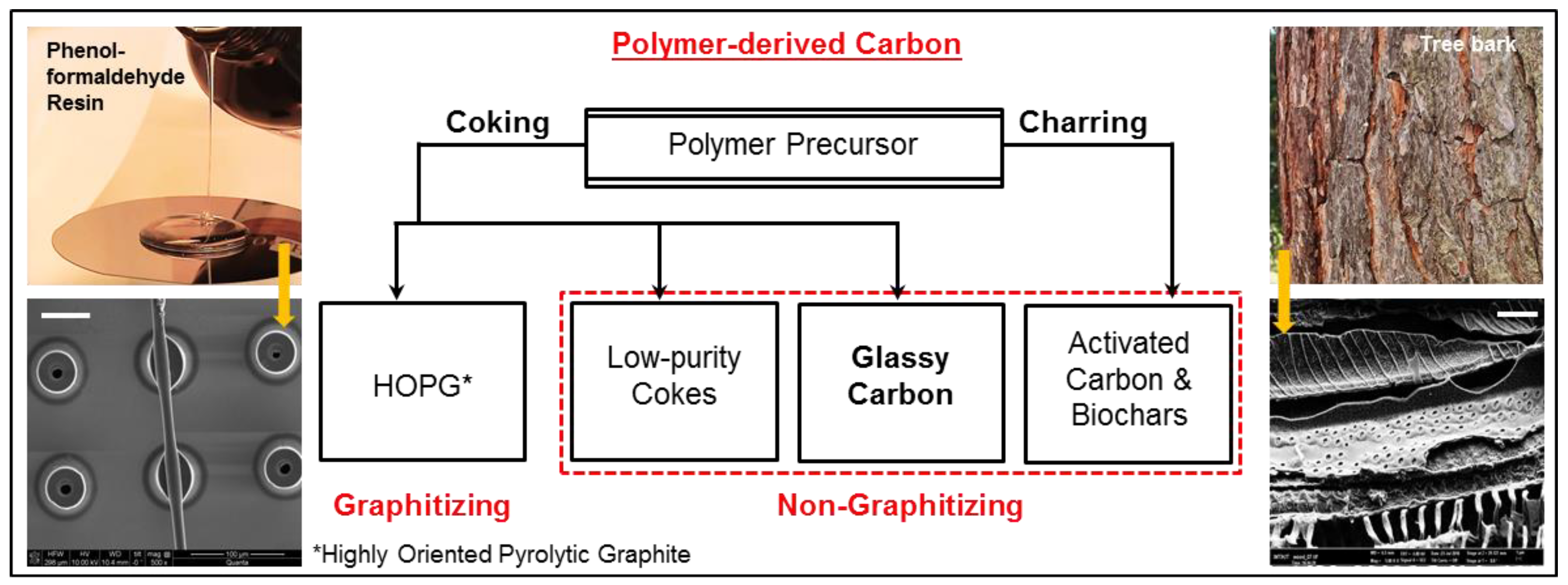
A classification of polymer-derived carbon based on the precursors is shown in Figure 1, followed by a brief explanation of the terminology.
4.1. Coking and Charring
If the pyrolysis product (mixture of all intermediate materials at any given temperature) goes through a semi-solid (rubbery) phase, owing to the fact that its Tg falls just below the process temperature [21,66], this phenomenon is known as coking [25]. The Scanning Electron Microscope (SEM) image in the bottom-left of Figure 1 represents a carbonized structure where a fiber was intentionally suspended onto an array of hollow micropillars (pillar diameter: ~5x fiber thickness; all structures fabricated in SU-8 [65]). It can be observed that the pillars attached to the fiber are deformed because of the tensile stretching in the fiber during pyrolysis. Other pillars shrink uniformly, indicating that the Tg of the pyrolysis mixture was only slightly below the set temperature. As this gap increases, the patterned structures further deform [21], and when it is significantly large (e.g., in the case of polyethylene), mostly oil-like materials are obtained [67]. The semi-solid intermediate material is responsible for a smooth surface of the resulting carbon, as it tries to minimize its surface energy. Examples of coking polymers are PF resins (yield non-graphitizing carbon [25]), and anthracene (yields graphitizing carbon [68]).
Charring refers to a direct conversion of the rigid polymer structure into carbon, where the shape is preserved both macro- and microscopically. Wood and other cellulosic polymers are good examples of charring (see the bottom-right SEM image in Figure 1). The major and most studied intermediate formed during cellulose pyrolysis is known as levoglucosan [69,70], which further disintegrates via different pathways leading to the formation of tars (oil-like materials), volatiles and solid carbon [70]. These phases generally coexist and remain distinct throughout the process. The solid carbon backbone is replicated in the final char, and the oils and volatiles are collected and distilled if so desired [1]. Cellulosic materials do encounter some softening in the 230–255 °C region, but it is not directly correlated with either Tg or the melting point [58]. Chars are predominantly non-graphitizing, and due to their porosity and surface chemistry, often serve as activated carbons. Pyrolysis of natural wood is more complex due to the presence of lignin and hemicellulose [1], which is not detailed here.
Carbonaceous residues obtained from biodegradable natural polymers at temperatures <900 °C are often called biochars. The term char may also occasionally signify the solid carbon formation from polymers, even after initial coking [25]. Importantly, the nomenclature of carbon materials is already full of ambiguities because of the existence of numerous carbon forms (including those with mixed hybridization), precursors and manufacturing processes. Any terminology that contributes to such confusions should therefore be avoided.
4.2. Graphitizing and Non-Graphitizing Carbon
Graphitizing carbons are those polymer-derived carbons that can potentially be converted into polycrystalline graphite by heat treatment [34,71], catalytic processes [72], stress [73] or any other method. Graphite features an ABABA crystal arrangement with a layer separation of 3.354 Å along the c-axis. During initial pyrolysis stages, certain semi-crystalline polymers, such as PVC, convert into a carbonaceous material that resembles stacked graphene fragments. Although initially these fragments contain impurities and have a turbostratic arrangement (randomly rotated basal planes), their progressive ordering at higher temperatures leads towards graphite formation [34,71]. Pyrolytic graphite can be post-processed to yield Highly Oriented Pyrolytic Graphite (HOPG). HOPG can also be obtained using other methods such as recrystallization from the iron melts (commercially known as Kish graphite), or thermal compression of chemically deposited graphene [33].
Non-graphitizing carbons, by definition, cannot be converted into crystalline graphite, as they contain various structural defects, and randomly oriented graphene fragments exhibiting a strong three-dimensional (3D) bonding. These turbostratic graphene fragments feature a Gaussian distribution in terms of size and shape, carbon-carbon bond-length and valance angles [74], and have an inter-layer separation >0.335 nm [25]. The presence of defects causes these fragments to curl, fold and form fullerene-like structures [75,76,77], and occasionally, completely closed buckminsterfullerenes [53]. The curved structures coexist with the larger, stacked graphene sheets [53]. Non-graphitizing carbons exhibit a lower electrical conductivity but an improved hardness compared to graphite, and are also called hard carbons. PF resins, cellulose, poly(vinylidene chloride), and certain polyimides yield non-graphitizing carbon on pyrolysis.
4.3. Glassy and Activated Carbon
Non-graphitizing carbon with a high purity that has experienced at least some coking during pyrolysis is known as glassy carbon. In the case of large (millimeter)-scale structures, glassy carbon is obtained at >2000 °C, since the pyrolysis intermediates may display a poor thermal conductivity causing a thermal gradient across the sample [78]. In order to systematically anneal out the volatiles and ensure purity all the way to the center of the structure, these elevated temperatures are essential. In some industrial processes, the preparation of glassy carbon is shown to take place at 1000 °C with modified pyrolysis conditions for ≤3 mm structural dimensions [60]. It has been confirmed by several studies that in the case of micro/nano scale structures, the properties of glassy carbon can be achieved at lower temperatures such as 900 °C (details in Section 5, Section 6 and Section 7), likely with some oxygen impurities.
Activated carbons are non-graphitizing carbons formed by direct charring that contain surface radicals and open pores. They have heteroatoms and more defects compared to glassy carbon, and their electrical conductivity and mechanical strength is typically lower. Owing to an active surface chemistry, they are often used as adsorbants and catalytic beds.
4.4. Carbon Fibers
Micro and nano scale fibers prepared by pyrolysis of cellulose, polyacrylonitrile (PAN), or other polymer fibers were traditionally not classified as glassy or activated based on the precursor chemistry [79]. However, with TEM becoming a common characterization tool for carbon materials [80], the microstructure of individual carbon fibers is increasingly being probed, and they are often labeled glassy, graphitic and graphitizing. As such, the annealing pattern in fibers is significantly different from the bulk due to a high surface-to-volume ratio. Surface treatment, fabrication parameters, and in the case of PAN, pre-pyrolysis oxidation can strongly influence their properties [79]. It has been reported that fibers tend to become more ordered (graphitic) if the fabrication process (typically electrospinning [81]) is modified [27], additives are incorporated [82], or stress is introduced [83,84]. Carbon fibers and solely fiber-based structures (e.g., tissue implants) are excluded from this review due to the vastness of the field.
5. Glassy Carbon Structures and Devices
As mentioned earlier, glassy carbon features closed porosity due to the presence of fullerene-like structures [76,85], which renders it impermeable to most gases and liquids i.e., chemically inert. Its defect-containing yet stable microstructure is resistant to crack propagation [86]. This property, integrated with a good thermal conductivity, contributes to its high thermal shock resistance. Other general properties of glassy carbon that are interesting from a manufacturing point of view are listed in Table 1. Importantly, the given values are for commercially available (bulk-manufactured) samples, which are typically mentioned in a range rather than as an absolute number, since glassy carbon is not a unique material. For further details regarding the material supplier/grade etc., respective reference articles may be consulted.
In addition to the experimental investigations, properties of glassy carbon under extreme conditions have also been examined theoretically [85]. The mechanical strength of glassy carbon is shown to further improve (at millimeter scale) by its artificial compression [90]. These properties, combined with the possibility of molding the precursor polymer into any desirable shape have been explored for a variety of applications. First, some large-scale applications are detailed, which served as the motivation for micro/nano devices.
5.1. Large-Scale Applications of Glassy Carbon
Glassy carbon has enabled some paradigm shifting technologies such as the fabrication of camera lenses [91] (used for glass molding), development of solid-state batteries (electrode material), and scale-up of harsh chemical processes, such as the crystallization of CaF2, CdS and ZnS under extreme P, T conditions (used as vessel liner) [25]. It is used in the manufacture of motor brushes, high temperature furnace elements, and laboratory crucibles previously manufactured using platinum or quartz [25]. Owing to its biocompatibility and mechanical strength, glassy carbon is a recommended material for the replacement of load-bearing joins in the human body [92], and has been studied as a dental implant material [93,94]. Two major challenges associated with the large-scale production of glassy carbon structures are: (i) high costs and (ii) dimensional shrinkage. The cost is directly related to the high processing temperatures, expensive raw materials, and the limitations associated with forming and molding the precursor resins [25]. The second issue, i.e., shrinkage, is inevitable since one must remove all possible non-carbon atoms from the material in order to achieve the useable properties, which leads to an overall mass loss. These challenges are addressed, and even turned into advantages in micro-/nanomanufacturing as described below.
5.2. Glassy Carbon in Micro/Nano Manufacturing
There are two possible pathways for manufacturing micro/nano scale structures using glassy carbon: (i) patterning a polymer followed by pyrolysis for its conversion into glassy carbon, or (ii) direct patterning of glassy carbon in the micro/nano scale. Pathway (i) enables a wider range of shapes without the need for machining, while pathway (ii) has the advantage of known material properties.
5.2.1. Fabrication via Pyrolysis of Polymer Structures
Lithographic techniques for patterning resins are well-studied, and are capable of sub-micron fabrication [16]. When these patterns are pyrolyzed, dimensional shrinkage becomes a tool for further size-reduction, which is otherwise beyond the capabilities of the employed fabrication technique. The thus obtained nano-scale structures offer an enhanced sensitivity and durability, for example, in biosensor applications. Due to a high surface-to-volume ratio of the individual structures, the volatile pyrolysis byproducts are easily annealed out. It has been reported that the material gains a higher crystallinity [27] and a much improved mechanical strength [14] at pyrolysis temperature as low as 900 °C at the nano scale. Selected examples of carbon devices fabricated using this approach from the recent literature are compiled in Table 2. Note that, in some of these articles, the term glassy carbon is not directly used, but the properties of the resulting material are shown to be very close to glassy carbon.
As evidenced by Table 2, the most common material for obtaining micro/nano glassy carbon structures is SU-8 (commercial product from MicroChem, MA, USA). SU-8 is a PF resin (Novolac type), which is extensively used in microfabrication [116], and is typically patterned using standard UV-(photo)lithography for the purpose of carbonization (see entries 1 to 13 in Table 2). UV-lithography is a relatively inexpensive batch fabrication technique [12] that can be optimized to yield <5 µm critical dimensions [104,108]. For large-area patterning of nano-scale structures, photo-nanoimprint lithography [16] is more suitable. This technique can potentially be utilized for obtaining a variety of structured glassy carbon surfaces. SU-8 is also compatible with 3D patterning such as by two-photon lithography [117] and single-photon-multi-layer-interference lithography [118]. However, to my knowledge, carbonization of truly 3D (not 2.5D) SU-8 structures has not been reported. Other polymers used in carbon-based microfarication include IP-resists (commercial product from Nanoscribe GmbH, Eggenstein-Leopoldshafen, Germany) [14,21,111] and various furan resins [112,113,114,115]. Furan resins and polyfurfuryl alcohols are polymers containing the basic furan ring structure [119] that are available in a wide range of viscosities (100 to 300000 centipoise [119]), and have been conventionally used for glassy carbon production. Yet, there are only a few examples of their use in small scale devices, likely due to the fact that they are commonly processed using soft-lithography [114,115] or molding, and entail more processing steps compared to photo-patterning. Microfabrication with furan resins has a lot of scope for further development.
Two major drawbacks of pyrolyzing the substrate-bound, pre-patterned structures for device purposes are (i) non-uniform structural shrinkage and (ii) lack of control over the substrate-carbon interface, occasionally leading to poor adhesion or pattern collapse. After carbonization, the material at the base (footprint) of the structure displays much less xy-shrinkage compared to the upper regions. While this effect can be neglected for high-aspect ratio structures, one may end-up with slanted walls as the shape becomes more 2D. Various parameters including the intended geometry, pyrolysis conditions and polymer viscosity influence the pyrolytic shrinkage [120].
Good adhesion onto the substrate is crucial for structures that are expected to experience mechanical or fluidic impact during subsequent operation (e.g., glass molding tools [114,115], microfluidic components [105,106] etc.). It can be improved by using adhesion promoters prior to lithography, optimizing the aspect ratio of the structure, and factoring-in the anticipated shrinkage. Direct machining of glassy carbon bypasses the two aforementioned limitations.
5.2.2. Fabrication via Direct Patterning of Glassy Carbon
Representative examples of the direct patterning of glassy carbon are listed in Table 3. Glassy carbon is a hard and brittle material. Therefore, its direct machining using conventional tools is extremely difficult. However, FIB milling [30] and various dry [31] and wet [28] etching methods have been effectively used to pattern it. Its exceptional inertness makes the chemical (wet) etching challenging, but an electrochemically assisted wet etch is generally possible [28], since glassy carbon does exhibit an electrochemical corrosion [121]. Dry etching is often carried out with the aid of reactive ions and/or high-density plasma. FIB milling is an expensive technique for patterning glassy carbon, but one can achieve a critical dimension of 5–10 µm using FIB. Such structures can be used as a master mold in the subsequent fabrication.
The main challenge associated with direct patterning methods is the resulting surface roughness [122,123]. While glassy carbon surface is characteristically smooth, machining-induced stresses can render it uneven due to its brittleness. Electrochemical wet etching of glassy carbon is capable of yielding submicron features, but its isotropic nature leads to undercuts [123]. Moreover, in the case of etching, regions with a higher crystallinity may have a different etch rate compared to those with defects and imperfections [55]. Laser ablation of glassy carbon suffers from reflections, and the heat generated during the process can potentially lead to altered surface properties [31]. In order to resolve some of these issues, oxidation assisted electrochemical machining [124] has been recently proposed. In this technique, an oxide layer is electrochemically formed (and regenerated) on the surface during its machining, which partly prevents it from getting damaged.
From Table 2 and Table 3, it is evident that electrode fabrication is one of the most common applications of glassy carbon, which has been extended to some fascinating research topics, such as neural stimulation and recording [95,96,97] and cell separation on microfluidic platforms [105,106]. These applications also benefit from glassy carbon’s biocompatibility, which is substantiated by successful cell culture on glassy carbon platforms [108,109,110].
6. Surface Modification of Glassy Carbon Electrodes
Electrodes entail a complete wetting by the electrolyte facilitated by an active surface. Electrode activation can be performed by mechanical polishing, washing, plasma treatment, thermal and laser activation, ultrasonication, and possibly by other methods [132]. This clean and activated electrode is either directly tested, or is subject to further chemical functionalization or electrochemical pretreatment [89,133] prior to its use. This involves an intentional grafting of radicals (e.g., NH4+ [134]) or electroactive species (e.g., hydroquinone [135]) specific to the desired application. The surface treatment can be taken one step further by ‘decorating’ the electrodes with other functional materials (e.g., nanoparticles [136], nanotubes [137], other nanocarbon units [138], and their composites [139]), which has been widely performed on glassy carbon. This is an indirect method of using glassy carbon in nano-scale devices, which has led to the development of a variety of electrochemical nano/bio sensors. A detailed analysis of the mechanism of various functionalization pathways can be found in a comprehensive review by McCreery [140].
Catalytic nanoparticles (gold, silver, metal oxides etc.), other carbon nanoforms and their composites may significantly improve the electrocatalytic performance of glassy carbon electrodes [141,142,143]. On the other hand, these nanomaterials benefit from glassy carbon’s high electrochemical and thermal stability [144], enhanced surface area [136], and corrosion resistance. Substrate support improves the available surface area of the nanomaterials, which facilitates a greater mass transport that is of paramount interest in catalysis [145]. Nanoparticles on carbon surfaces are either obtained by reducing metals from their respective salts, or by attaching pre-formed nanoparticles. The adhesion of particles is considerably better in the case of salt reduction, however, pre-synthesized particles allow for a better control over their geometry and other physicochemical properties [146]. Modified electrodes are frequently coated with ionic polymers (e.g., nafionTM) to partially block the neutral molecules from reaching the functional element [147].
Selected examples of glassy carbon electrode modification via decoration with other materials are listed in Table 4. The modifying agents are divided into four categories for convenience, and only five examples from each are provided, since the idea here is to present surface modification as a possibility for further sensitivity improvement of miniaturized glassy carbon devices (one such example [107] is listed in Table 2). Notably, in the case of multilayer or composite material coatings, the exact mechanism of the electrocatalytic activity as well as the contribution from glassy carbon itself is occasionally not completely understood. The overall electrode performance, however, is shown to enhance. It is also worth mentioning that the boundaries between surface activation, functionalization, modification and decoration are difficult to set, since every treatment does modify the surface to some extent.
7. Characterization of Glassy Carbon
Ensuring that a polymer-derived carbon with an unknown pyrolysis mechanism is glassy carbon is tricky, especially in the micro/nano scale where the first hand visual and physical observations (e.g., glass-like shine) are difficult. Most of the established characterization techniques have specific sample requirements (powders, ultra-thin slices, specialized substrates etc.). In order to satisfy them, one may end up preparing structures of different geometries and surface area compared to what is actually used in the device. Since the annealing mechanism is critical in determining the material purity and porosity [53,60], it is likely to find microstructural variations caused by the sample geometry. To avoid this, one should utilize the techniques that are designed to analyze micro/nano structures where possible, or modify the sample geometry in a way that is not too far from the original. For example, elemental purity can be determined using Energy Dispersive X-ray (EDX) spectroscopy [121], rather than by combustion analysis; or Raman spectroscopy can be performed on an array of microfabricated structures rather than the powder obtained from the same polymer. It is not straightforward to determine whether or not a polymer experiences coking at the micro/nano length scales. One option is to intentionally design a structure that will experience a non-uniform shrinkage during pyrolysis. If it shows bending, twisting or stretching rather than fracturing, this confirms that during the initial pyrolysis stages the material had some viscoelasticity. Importantly, after cooling down, the material becomes hard and brittle in all cases.
Broadly, there are three major aspects of the characterization of polymer-derived carbon: (i) microstructure (to differentiate between graphitizing and non-graphitizing), (ii) surface chemistry and porosity (to establish if it is glassy or activated), and (iii) physicochemical properties (mechanical, electrical, electrochemical) to further narrow down the carbon class. Additionally, elemental purity entails validation in specific cases (for example, when pyrolysis conditions are modified). Commonly used microstructural characterization techniques include XRD [74,164], Raman spectroscopy [164], TEM (preferably low-voltage [53]; can be integrated with Electron Energy Loss Spectroscopy or EELS [165]) and certain physicochemical properties (e.g., electrical conductivity). Surface flatness is generally observed by SEM or AFM measurements, and the chemical nature of the surface is investigated using contact angle measurements (first approximation), and by XPS (detailed surface functional group analysis). Pyrolysis mechanism can be probed using Electron Paramagnetic Resonance [33,52], and the graphitization can be substantiated with magnetoresistance evaluation [38] where possible. All aforementioned techniques complement each other, and may not provide sufficient data as standalone. Further property tests are application-specific.
8. Further Discussion Points
8.1. Should the Term ‘Glass-Like Carbon’ Be Used Instead of ‘Glassy Carbon’?
According to the IUPAC nomenclature [166], ‘glassy’ and ‘vitreous’ carbon should not be used to denote this material since these terms (i) have been used as trademarks and (ii) give the impression that the material properties are similar to those of amorphous glasses (e.g., silicates), which is incorrect. Despite this recommendation, several pioneering publications and fundamental books used by students and early career researchers contain the term glassy carbon. Subsequently, it is reflected in the Internet search, and is listed as a keyword various publications. Although this is an open question and the choice of the appropriate term is left to the authors, the term glassy carbon is used in this article simply to ensure its wider dissemination.
8.2. Is 900 °C a High Enough Temperature to Obtain Glassy Carbon?
One common criticism faced by microsystem engineers is that the carbon obtained below 2000 °C may contain oxygen, and hence, should not be called glassy carbon. Here it is essential to understand that lithographic patterning of polymers entails a substrate, which is typically silicon. The melting point of silicon is 1410 °C however, it may experience thermal fatigue and deform at slightly lower temperatures [167]. Consequently, 900–1200 °C is chosen as the optimum carbonization temperature range for lithography-based devices. It has been frequently reported that the micro/nano carbon structures pyrolyzed at 900 °C feature properties similar to commercial glassy carbons, which is attributed to the high surface-to-volume ratio of the smaller structures that allows them to attain a low porosity and higher purity compared to larger structures at the same temperature. Oxygen impurities, however, are plausible. The exact correlation between structure size, pyrolysis temperature and material properties is a topic for further investigation. A potential solution is to mention the pyrolysis temperature in the label (e.g., glassy carbon-900) in order to avoid ambiguities.
9. Conclusions
There are vast global interests in carbon nanomaterials as well as in promoting commercially viable micro- and nanomanufacturing processes. Glassy carbon is an ideal material for this purpose because: (i) it is composed of a stable, percolated graphenic network, is corrosion-free, and hence, remarkably durable at the nano-scale, (ii) it is an elemental carbon form that offers multiple advantages over composites, principally, the availability of all physicochemical properties of the pristine form, (iii) 2.5- and 3D structures can be batch-fabricated by lithographic techniques, (iv) micro-scale techniques can be employed in nanomanufacturing due to the pyrolysis-induced size reduction, and (v) numerous surface modification opportunities without compromising the material properties can be availed. The established large-scale applications of glassy carbon have already proven its commercial viability. Further cost reduction is possible by lowering the required pyrolysis temperature by introducing additives and catalysts in the precursor polymers, development of high performance resins at lower costs, and by moving from batch to continuous manufacturing. There is a substantial scope in the development of direct patterning methods for glassy carbon, for example, by customized etching methods and the use of high-intensity ion and laser beams as direct-writing tools. Owing to its compatibility with 3D microfabrication, this material can potentially be used in a variety of high-aspect ratio devices.
Author Contributions
All contents of this article are prepared by S.S.
Funding
Author thanks the Ministry of Science, Research and Arts, Baden-Württemberg, Germany (Grant No. Az:33-7533-30-20/3/3, HEiKA Center FunTECH-3D); and project BioPEC, jointly supported by the Federal Ministry of Education and Research (BMBF), Germany (Ref. No. 01DQ17014) and the Department of Biotechnology (DBT), India (Ref. No. BT/IN/BMBF-Germany/29/SKM/2016-17) for financial support.
Acknowledgments
Author sincerely thanks Aakanksha Khurana and Akhilesh Sharma, Punjab Engineering College, Chandigarh, India (supported by PEBA at KIT; www.peba.kit.edu) for help in literature survey. Author also expresses gratitude to the Deutsche Forschungsgemeinschaft and Open Access Publishing Fund of the Karlsruhe Institute of Technology.
Conflicts of Interest
The author declares no conflict of interest.
References
- González-García, P. Activated carbon from lignocellulosics precursors: A review of the synthesis methods, characterization techniques and applications. Renew. Sustain. Energy Rev. 2018, 82, 1393–1414. [Google Scholar] [CrossRef]
- Haddon, R.C. pi.-Electrons in three dimensions. Acc. Chem. Res. 1988, 21, 243–249. [Google Scholar] [CrossRef]
- Haddon, R.C.; Palmer, R.E.; Kroto, H.W.; Sermon, P.A. The Fullerenes: Powerful Carbon-Based Electron Acceptors. Philos. Trans. Phys. Sci. Eng. 1993, 343, 53–62. [Google Scholar]
- Zhu, Z. An Overview of Carbon Nanotubes and Graphene for Biosensing Applications. Nano-Micro Lett. 2017, 9. [Google Scholar] [CrossRef]
- Chae, S.H.; Lee, Y.H. Carbon nanotubes and graphene towards soft electronics. Nano Converg. 2014, 1. [Google Scholar] [CrossRef] [PubMed]
- Sun, D.M.; Liu, C.; Ren, W.C.; Cheng, H.M. A Review of Carbon Nanotube- and Graphene-Based Flexible Thin-Film Transistors. Small 2013, 9, 1188–1205. [Google Scholar] [CrossRef] [PubMed]
- Bandodkar, A.J.; Jeerapan, I.; You, J.-M.; Nuñez-Flores, R.; Wang, J. Highly Stretchable Fully-Printed CNT-Based Electrochemical Sensors and Biofuel Cells: Combining Intrinsic and Design-Induced Stretchability. Nano Lett. 2016, 16, 721–727. [Google Scholar] [CrossRef] [PubMed]
- Kholghi Eshkalak, S.; Chinnappan, A.; Jayathilaka, W.A.D.M.; Khatibzadeh, M.; Kowsari, E.; Ramakrishna, S. A review on inkjet printing of CNT composites for smart applications. Appl. Mater. Today 2017, 9, 372–386. [Google Scholar] [CrossRef]
- Njuguna, J.; Pielichowski, K.; Zhu, H. (Eds.) Health and Environmental Safety of Nanomaterials: Polymer Nanocomposites and Other Materials Containing Nanoparticles; Woodhead Publishing Series in Composites Science and Engineering; Woodhead Publishing: Cambridge, UK; Waltham, MA, USA, 2014; ISBN 978-0-85709-655-5. [Google Scholar]
- Rammohan, A.; Sharma, A. Carbon as a MEMS Material. In Materials and Failures in MEMS and NEMS; Tiwari, A., Raj, B., Eds.; John Wiley & Sons, Inc.: Hoboken, NJ, USA, 2015; pp. 1–20. ISBN 978-1-119-08388-7. [Google Scholar]
- Madou, M.J.; Perez-Gonzalez, V.H.; Pramanick, B. (Eds.) Carbon, the Next Silicon; Momentum Press: New York, NY, USA, 2016; ISBN 978-1-60650-883-1. [Google Scholar]
- Sharma, S.; Madou, M. Micro and nano patterning of carbon electrodes for bioMEMS. Bioinspired Biomim. Nanobiomater. 2012, 1, 252–265. [Google Scholar] [CrossRef]
- Sekkat, Z.; Kawata, S. Laser nanofabrication in photoresists and azopolymers: Laser nanofabrication in photoresists and azopolymers. Laser Photonics Rev. 2014, 8, 1–26. [Google Scholar] [CrossRef]
- Bauer, J.; Schroer, A.; Schwaiger, R.; Kraft, O. Approaching theoretical strength in glassy carbon nanolattices. Nat. Mater. 2016, 15, 438–443. [Google Scholar] [CrossRef] [PubMed]
- Cadarso, V.J.; Chidambaram, N.; Jacot-Descombes, L.; Schift, H. High-aspect-ratio nanoimprint process chains. Microsyst. Nanoeng. 2017, 3, 17017. [Google Scholar] [CrossRef] [Green Version]
- Penmatsa, V.; Kawarada, H.; Wang, C. Fabrication of carbon nanostructures using photo-nanoimprint lithography and pyrolysis. J. Micromech. Microeng. 2012, 22, 045024. [Google Scholar] [CrossRef]
- Maldonado, J.R.; Peckerar, M. X-ray lithography: Some history, current status and future prospects. Microelectron. Eng. 2016, 161, 87–93. [Google Scholar] [CrossRef]
- Reichmanis, E.; Houlihan, F.M.; Nalamasu, O.; Neenan, T.X. Chemical Amplification Mechanisms for Microlithography. In Polymers for Microelectronics; Thompson, L.F., Willson, C.G., Tagawa, S., Eds.; American Chemical Society: Washington, DC, USA, 1993; Volume 537, pp. 2–24. ISBN 978-0-8412-2721-7. [Google Scholar]
- Vilčáková, J.; Kutějová, L.; Jurča, M.; Moučka, R.; Vícha, R.; Sedlačík, M.; Kovalcik, A.; Machovský, M.; Kazantseva, N. Enhanced Charpy impact strength of epoxy resin modified with vinyl-terminated polydimethylsiloxane: Research Article. J. Appl. Polym. Sci. 2018, 135, 45720. [Google Scholar] [CrossRef]
- Anthony, R.; Laforge, E.; Casey, D.P.; Rohan, J.F.; O’Mathuna, C. High-aspect-ratio photoresist processing for fabrication of high resolution and thick micro-windings. J. Micromech. Microeng. 2016, 26, 105012. [Google Scholar] [CrossRef]
- Zakhurdaeva, A.; Dietrich, P.-I.; Hölscher, H.; Koos, C.; Korvink, J.; Sharma, S. Custom-Designed Glassy Carbon Tips for Atomic Force Microscopy. Micromachines 2017, 8, 285. [Google Scholar] [CrossRef]
- Lin, Q. Properties of Photoresist Polymers. In Physical Properties of Polymers Handbook; Mark, J.E., Ed.; Springer: New York, NY, USA, 2007; pp. 965–979. ISBN 978-0-387-31235-4. [Google Scholar]
- Mojarad, N.; Gobrecht, J.; Ekinci, Y. Beyond EUV lithography: A comparative study of efficient photoresists’ performance. Sci. Rep. 2015, 5, 9235. [Google Scholar] [CrossRef] [PubMed]
- Chiang, D.; Chang, C.-M.; Chen, S.-W.; Yang, C.-T.; Hsueh, W.-J. Physical properties of an oxide photoresist film for submicron pattern lithography. Thin Solid Films 2013, 542, 409–414. [Google Scholar] [CrossRef]
- Jenkins, G.M.; Kawamura, K. Polymeric Carbons–Carbon Fibre, Glass and Char; Cambridge University Press: Cambridge, UK; New York, NY, USA, 1976; ISBN 0-521-20693-8. [Google Scholar]
- Lehrle, R.S. Polymer pyrolysis mechanisms: Experimental approaches for investigating them. J. Anal. Appl. Pyrolysis 1987, 11, 55–64. [Google Scholar] [CrossRef]
- Sharma, S.; Sharma, A.; Cho, Y.-K.; Madou, M. Increased Graphitization in Electrospun Single Suspended Carbon Nanowires Integrated with Carbon-MEMS and Carbon-NEMS Platforms. ACS Appl. Mater. Interfaces 2012, 4, 34–39. [Google Scholar] [CrossRef] [PubMed]
- Kiema, G.K.; Ssenyange, S.; McDermott, M.T. Microfabrication of Glassy Carbon by Electrochemical Etching. J. Electrochem. Soc. 2004, 151, C142. [Google Scholar] [CrossRef]
- Pleshkova, L.S.; Shesterkin, V.I. Effect of the glassy carbon structure on the aspect ratio of micropoints of matrix field-emission cathodes prepared by thermochemical etching. Tech. Phys. 2016, 61, 1747–1750. [Google Scholar] [CrossRef]
- Youn, S.W.; Takahashi, M.; Goto, H.; Maeda, R. A study on focused ion beam milling of glassy carbon molds for the thermal imprinting of quartz and borosilicate glasses. J. Micromech. Microeng. 2006, 16, 2576–2584. [Google Scholar] [CrossRef]
- Kuhnke, M.; Lippert, T.; Ortelli, E.; Scherer, G.; Wokaun, A. Microstructuring of glassy carbon: Comparison of laser machining and reactive ion etching. Thin Solid Films 2004, 453–454, 36–41. [Google Scholar] [CrossRef]
- Walker, P.L. Chemistry and Physics of Carbon: A Series of Advances; Marcel Dekker, Inc.: New York, NY, USA, 1965; Volume 1. [Google Scholar]
- Walker, P.L.; Thrower, P.A. Chemistry and Physics of Carbon: A Series of Advances; Marcel Dekker, Inc.: New York, NY, USA; Basel, Switzerland, 1975; Volume 12, ISBN 978-0-8247-6304-6. [Google Scholar]
- Franklin, R.E. Crystallite Growth in Graphitizing and Non-Graphitizing Carbons. Proc. R. Soc. A Math. Phys. Eng. Sci. 1951, 209, 196–218. [Google Scholar] [CrossRef]
- Jenkins, G.M.; Kawamura, K. Structure of Glassy Carbon. Nature 1971, 231, 175–176. [Google Scholar] [CrossRef] [PubMed]
- Pesin, L.; Baitinger, E. A new structural model of glass-like carbon. Carbon 2002, 40, 295–306. [Google Scholar] [CrossRef]
- Presland, A.E.B.; Walker, P.L. Growth of single-crystal graphite by pyrolysis of acetylene over metals. Carbon 1969, 7, 1–8. [Google Scholar] [CrossRef]
- Walker, P.L. Chemistry and Physics of Carbon: A Series of Advances; Marcel Dekker, Inc.: New York, NY, USA; Basel, Switzerland, 1981; Volume 16, ISBN 978-0-8247-6991-8. [Google Scholar]
- Chaala, A.; Roy, C. Production of coke from scrap tire vacuum pyrolysis oil. Fuel Process. Technol. 1996, 46, 227–239. [Google Scholar] [CrossRef]
- Martínez-Escandell, M.; Torregrosa, P.; Marsh, H.; Rodríguez-Reinoso, F.; Santamaría-Ramírez, R.; Gómez-De-Salazar, C.; Romero-Palazón, E. Pyrolysis of petroleum residues: I. Yields and product analyses. Carbon 1999, 37, 1567–1582. [Google Scholar] [CrossRef]
- Zádor, J.; Fellows, M.D.; Miller, J.A. Initiation Reactions in Acetylene Pyrolysis. J. Phys. Chem. A 2017, 121, 4203–4217. [Google Scholar] [CrossRef] [PubMed]
- Amirov, R.K.; Atamanuk, I.N.; Vorobieva, N.A.; Isakaev, E.H.; Shavelkina, M.B.; Shkolnikov, E.I. Synthesis of graphene-like materials by pyrolysis of hydrocarbons in thermal plasma and their properties. J. Phys. Conf. Ser. 2015, 653, 012161. [Google Scholar] [CrossRef] [Green Version]
- Zhang, Y.; Zhang, L.; Zhou, C. Review of Chemical Vapor Deposition of Graphene and Related Applications. Acc. Chem. Res. 2013, 46, 2329–2339. [Google Scholar] [CrossRef] [PubMed]
- Wang, S.; Luo, Z. Pyrolysis of Biomass; GREEN Alternative Energy Resources; De Gruyter; Science Press: Beijing, China, 2017; ISBN 978-3-11-037457-5. [Google Scholar]
- Tudu, K.; Murugan, S.; Patel, S.K. Light Oil Fractions from a Pyrolysis Plant—An Option for Energy Use. Energy Procedia 2014, 54, 615–626. [Google Scholar] [CrossRef]
- Sahota, S.; Shah, G.; Ghosh, P.; Kapoor, R.; Sengupta, S.; Singh, P.; Vijay, V.; Sahay, A.; Vijay, V.K.; Thakur, I.S. Review of trends in biogas upgradation technologies and future perspectives. Bioresour. Technol. Rep. 2018, 1, 79–88. [Google Scholar] [CrossRef]
- Brugner, F.; Jonnatti, A. An Air Pyrolysis Study of Cast Bisphenol a Epoxy Transformer Coils. IEEE Trans. Power Appar. Syst. 1983, PAS-102, 2203–2207. [Google Scholar] [CrossRef]
- Kantarelis, E.; Yang, W.; Blasiak, W. Production of Liquid Feedstock from Biomass via Steam Pyrolysis in a Fluidized Bed Reactor. Energy Fuels 2013, 27, 4748–4759. [Google Scholar] [CrossRef]
- Gupta, C.K. Chemical Metallurgy; Wiley-VCH Verlag GmbH & Co. KGaA: Weinheim, Germany, 2003; ISBN 978-3-527-30376-2. [Google Scholar]
- Dunn, J.G.; Chamberlain, A.C. The recovery of gold from refractory arsenopyrite concentrates by pyrolysis-oxidation. Miner. Eng. 1997, 10, 919–928. [Google Scholar] [CrossRef]
- Hoffman, W.P.; Vastola, F.J.; Walker, P.L. Pyrolysis of propylene over carbon active sites II. Pyrolysis products. Carbon 1988, 26, 485–499. [Google Scholar] [CrossRef]
- Sharma, S.; Rostas, A.M.; Bordonali, L.; MacKinnon, N.; Weber, S.; Korvink, J.G. Micro and nano patternable magnetic carbon. J. Appl. Phys. 2016, 120, 235107. [Google Scholar] [CrossRef] [Green Version]
- Sharma, S.; Kumar, C.N.S.; Korvink, J.G.; Kübel, C. Evolution of Glassy Carbon Microstructure: In Situ Transmission Electron Microscopy of the Pyrolysis Process. arXiv, 2018; arXiv:1801.01785. [Google Scholar]
- Bennett, A.; Payne, D.R.; Court, R.W. Pyrolytic and Elemental Analysis of Decomposition Products from a Phenolic Resin. Macromol. Symp. 2014, 339, 38–47. [Google Scholar] [CrossRef]
- Sharma, S.; Kamath, R.; Madou, M. Porous glassy carbon formed by rapid pyrolysis of phenol-formaldehyde resins and its performance as electrode material for electrochemical double layer capacitors. J. Anal. Appl. Pyrolysis 2014, 108, 12–18. [Google Scholar] [CrossRef]
- Pesin, L. Review: Structure and properties of glass-like carbon. J. Mater. Sci. 2002, 37, 1–28. [Google Scholar] [CrossRef]
- Brooks, J.D.; Taylor, G.H. The formation of graphitizing carbons from the liquid phase. Carbon 1965, 3, 185–193. [Google Scholar] [CrossRef]
- Lédé, J. Cellulose pyrolysis kinetics: An historical review on the existence and role of intermediate active cellulose. J. Anal. Appl. Pyrolysis 2012, 94, 17–32. [Google Scholar] [CrossRef]
- Edstrom, T.; Lewis, I.C. Chemical structure and graphitization: X-ray diffraction studies of graphites derived from polynuclear aromatics. Carbon 1969, 7, 85–91. [Google Scholar] [CrossRef]
- Maleki, H.; Holland, L.R.; Jenkins, G.M.; Zimmerman, R.L. Determining the shortest production time for glassy carbon ware. Carbon 1997, 35, 227–234. [Google Scholar] [CrossRef]
- Fitzer, E.; Schäfer, W. The effect of crosslinking on the formation of glasslike carbons from thermosetting resins. Carbon 1970, 8, 353–364. [Google Scholar] [CrossRef]
- Desai, T.G.; Lawson, J.W.; Keblinski, P. Modeling initial stage of phenolic pyrolysis: Graphitic precursor formation and interfacial effects. Polymer 2011, 52, 577–585. [Google Scholar] [CrossRef]
- Liu, J.; Guo, X. ReaxFF molecular dynamics simulation of pyrolysis and combustion of pyridine. Fuel Process. Technol. 2017, 161, 107–115. [Google Scholar] [CrossRef]
- Kruse, T.M.; Wong, H.-W.; Broadbelt, L.J. Mechanistic Modeling of Polymer Pyrolysis: Polypropylene. Macromolecules 2003, 36, 9594–9607. [Google Scholar] [CrossRef]
- Sharma, S. Microstructural Tuning of Glassy Carbon for Electrical and Electrochemical Sensor Applications; University of California: Irvine, CA, USA, 2013; ISBN 978-1-303-60368-6. [Google Scholar]
- Biryukova, G.P.; Shablygin, M.V.; Mikhailov, N.V.; Andrianov, K.A. Relationship between the conditions of pyrolysis and the structural and chemical transformation of cellulose hydrate. Polym. Sci. USSR 1973, 15, 1762–1766. [Google Scholar] [CrossRef]
- Obeid, F.; Janajreh, I. High Density Polyethylene Pyrolysis: Review and Progress. In ICREGA’14—Renewable Energy: Generation and Applications; Hamdan, M.O., Hejase, H.A.N., Noura, H.M., Fardoun, A.A., Eds.; Springer International Publishing: Cham, Switzerland, 2014; pp. 585–595. ISBN 978-3-319-05707-1. [Google Scholar]
- Stein, S.E. Thermochemical kinetics of anthracene pyrolysis. Carbon 1981, 19, 421–429. [Google Scholar] [CrossRef]
- Maduskar, S.; Maliekkal, V.; Neurock, M.; Dauenhauer, P.J. On the Yield of Levoglucosan from Cellulose Pyrolysis. ACS Sustain. Chem. Eng. 2018, 6, 7017–7025. [Google Scholar] [CrossRef]
- Lewellen, P.C.; Peters, W.A.; Howard, J.B. Cellulose pyrolysis kinetics and char formation mechanism. Symp. Int. Combust. 1977, 16, 1471–1480. [Google Scholar] [CrossRef]
- Walker, P.L.; Thrower, P.A. Chemistry and Physics of Carbon: A Series of Advances; Marcel Dekker, Inc.: New York, NY, USA, 1973; Volume 10, ISBN 978-0-8247-6072-4. [Google Scholar]
- Hirano, S.-I.; Nakamura, K.; Sōmiya, S. Graphitization of Carbon in Presence of Calcium Compounds under Hydrothermal Condition by Use of High Gas Pressure Apparatus. In Hydrothermal Reactions for Materials Science and Engineering; Sōmiya, S., Ed.; Springer: Dordrecht, The Netherlands, 1989; pp. 331–336. ISBN 978-94-010-6819-2. [Google Scholar]
- Bragg, R.; Crooks, D.; Fenn, R.; Hammond, M. The effect of applied stress on the graphitization of pyrolytic graphite. Carbon 1964, 1, 171–179. [Google Scholar] [CrossRef]
- Jurkiewicz, K.; Duber, S.; Fischer, H.E.; Burian, A. Modelling of glass-like carbon structure and its experimental verification by neutron and X-ray diffraction. J. Appl. Crystallogr. 2017, 50, 36–48. [Google Scholar] [CrossRef]
- Harris, P.J.F. On charcoal. Interdiscip. Sci. Rev. 1999, 24, 301–306. [Google Scholar] [CrossRef]
- Harris, P.J.F. Fullerene-related structure of commercial glassy carbons. Philos. Mag. 2004, 84, 3159–3167. [Google Scholar] [CrossRef] [Green Version]
- Harris, P.J.F.; Tsang, S.C. High-resolution electron microscopy studies of non-graphitizing carbons. Philos. Mag. A 1997, 76, 667–677. [Google Scholar] [CrossRef] [Green Version]
- Hancox, R.N.; Lamb, G.D.; Lehrle, R.S. Sample size dependence in pyrolysis: An embarrassment, or a utility? J. Anal. Appl. Pyrolysis 1991, 19, 333–347. [Google Scholar] [CrossRef]
- Donnet, J.-B. (Ed.) Carbon Fibers, 3rd ed.; Marcel Dekker: New York, NY, USA, 1998; ISBN 978-0-8247-0172-7. [Google Scholar]
- Harris, P.J.F. Transmission Electron Microscopy of Carbon: A Brief History. C 2018, 4, 4. [Google Scholar] [CrossRef]
- Inagaki, M.; Yang, Y.; Kang, F. Carbon Nanofibers Prepared via Electrospinning. Adv. Mater. 2012, 24, 2547–2566. [Google Scholar] [CrossRef] [PubMed]
- Maitra, T.; Sharma, S.; Srivastava, A.; Cho, Y.-K.; Madou, M.; Sharma, A. Improved graphitization and electrical conductivity of suspended carbon nanofibers derived from carbon nanotube/polyacrylonitrile composites by directed electrospinning. Carbon 2012, 50, 1753–1761. [Google Scholar] [CrossRef]
- Johnson, J.W.; Marjoram, J.R.; Rose, P.G. Stress Graphitization of Polyacrylonitrile Based Carbon Fibre. Nature 1969, 221, 357–358. [Google Scholar] [CrossRef]
- Ghazinejad, M.; Holmberg, S.; Pilloni, O.; Oropeza-Ramos, L.; Madou, M. Graphitizing Non-graphitizable Carbons by Stress-induced Routes. Sci. Rep. 2017, 7, 16551. [Google Scholar] [CrossRef] [PubMed]
- Zhao, Z.; Wang, E.F.; Yan, H.; Kono, Y.; Wen, B.; Bai, L.; Shi, F.; Zhang, J.; Kenney-Benson, C.; Park, C.; et al. Nanoarchitectured materials composed of fullerene-like spheroids and disordered graphene layers with tunable mechanical properties. Nat. Commun. 2015, 6, 6212. [Google Scholar] [CrossRef] [PubMed] [Green Version]
- Awaji, H.; Choi, S.-M. Thermal Shock Tests and Thermal Shock Parameters for Ceramics. J. Korean Ceram. Soc. 2012, 49, 385–396. [Google Scholar] [CrossRef] [Green Version]
- Garion, C. Mechanical Properties for Reliability Analysis of Structures in Glassy Carbon. World J. Mech. 2014, 4, 79–89. [Google Scholar] [CrossRef]
- Fischbach, D.B. Magnetic susceptibility of glassy carbon. Carbon 1967, 5, 565–570. [Google Scholar] [CrossRef] [Green Version]
- Kinoshita, K. Carbon: Electrochemical and Physicochemical Properties; Wiley: New York, NY, USA, 1988; ISBN 978-0-471-84802-8. [Google Scholar]
- Hu, M.; He, J.; Zhao, Z.; Strobel, T.A.; Hu, W.; Yu, D.; Sun, H.; Liu, L.; Li, Z.; Ma, M.; et al. Compressed glassy carbon: An ultrastrong and elastic interpenetrating graphene network. Sci. Adv. 2017, 3, e1603213. [Google Scholar] [CrossRef] [PubMed]
- Angle, M.; Blair, G.; Maier, C. Method for Molding Glass Lenses. U.S. Patent No. 3833347, 3 September 1974. [Google Scholar]
- Stanley, J.; Klawitter, J.; More, R. Replacing joints with pyrolytic carbon. In Joint Replacement Technology; Elsevier: Amsterdam, The Netherlands, 2008; pp. 631–656. ISBN 978-1-84569-245-2. [Google Scholar]
- Schnitman, P.A.; Woolfson, M.W.; Feingold, R.M.; Gettleman, L.; Freedman, H.M.; Kalis, P.J.; Buchanan, W.; Shulman, L.B. Vitreous carbon implants: A five-year study in baboons. J. Prosthet. Dent. 1980, 44, 190–200. [Google Scholar] [CrossRef]
- Hucke, E.E.; Fuys, R.A.; Craig, R.G. Glassy carbon: A potential dental implant material. J. Biomed. Mater. Res. 1973, 7, 263–274. [Google Scholar] [CrossRef] [PubMed]
- VanDersarl, J.J.; Mercanzini, A.; Renaud, P. Integration of 2D and 3D Thin Film Glassy Carbon Electrode Arrays for Electrochemical Dopamine Sensing in Flexible Neuroelectronic Implants. Adv. Funct. Mater. 2015, 25, 78–84. [Google Scholar] [CrossRef]
- Vomero, M.; Castagnola, E.; Ciarpella, F.; Maggiolini, E.; Goshi, N.; Zucchini, E.; Carli, S.; Fadiga, L.; Kassegne, S.; Ricci, D. Highly Stable Glassy Carbon Interfaces for Long-Term Neural Stimulation and Low-Noise Recording of Brain Activity. Sci. Rep. 2017, 7, 40332. [Google Scholar] [CrossRef] [PubMed] [Green Version]
- Castagnola, E.; Winchester Vahidi, N.; Nimbalkar, S.; Rudraraju, S.; Thielk, M.; Zucchini, E.; Cea, C.; Carli, S.; Gentner, T.Q.; Ricci, D.; et al. In Vivo Dopamine Detection and Single Unit Recordings Using Intracortical Glassy Carbon Microelectrode Arrays. MRS Adv. 2018, 3, 1629–1634. [Google Scholar] [CrossRef] [PubMed]
- Yildizhan, Y.; Erdem, N.; Islam, M.; Martinez-Duarte, R.; Elitas, M. Dielectrophoretic Separation of Live and Dead Monocytes Using 3D Carbon-Electrodes. Sensors 2017, 17, 2691. [Google Scholar] [CrossRef] [PubMed]
- Hirabayashi, M.; Mehta, B.; Nguyen, B.; Kassegne, S. DNA immobilization on high aspect ratio glassy carbon (GC-MEMS) microelectrodes for bionanoelectronics applications. Microsyst. Technol. 2015, 21, 2359–2365. [Google Scholar] [CrossRef]
- Mohamed Hassan, Y.; Caviglia, C.; Hemanth, S.; Mackenzie, D.M.A.; Petersen, D.H.; Keller, S.S. Pyrolytic carbon microelectrodes for impedance based cell sensing. ECS Trans. 2016, 72, 35–44. [Google Scholar] [CrossRef] [Green Version]
- Mardegan, A.; Kamath, R.; Sharma, S.; Scopece, P.; Ugo, P.; Madou, M. Optimization of Carbon Electrodes Derived from Epoxy-based Photoresist. J. Electrochem. Soc. 2013, 160, B132–B137. [Google Scholar] [CrossRef] [Green Version]
- Sharma, S.; Madou, M. A new approach to gas sensing with nanotechnology. Philos. Trans. R. Soc. A Math. Phys. Eng. Sci. 2012, 370, 2448–2473. [Google Scholar] [CrossRef] [PubMed]
- Thiha, A.; Ibrahim, F.; Muniandy, S.; Dinshaw, I.J.; Teh, S.J.; Thong, K.L.; Leo, B.F.; Madou, M. All-carbon suspended nanowire sensors as a rapid highly-sensitive label-free chemiresistive biosensing platform. Biosens. Bioelectron. 2018, 107, 145–152. [Google Scholar] [CrossRef] [PubMed]
- Kamath, R.R.; Madou, M.J. Three-Dimensional Carbon Interdigitated Electrode Arrays for Redox-Amplification. Anal. Chem. 2014, 86, 2963–2971. [Google Scholar] [CrossRef] [PubMed]
- Elitas, M.; Martinez-Duarte, R.; Dhar, N.; McKinney, J.D.; Renaud, P. Dielectrophoresis-based purification of antibiotic-treated bacterial subpopulations. Lab Chip 2014, 14, 1850–1857. [Google Scholar] [CrossRef] [PubMed]
- Jaramillo, M.d.C.; Martínez-Duarte, R.; Hüttener, M.; Renaud, P.; Torrents, E.; Juárez, A. Increasing PCR sensitivity by removal of polymerase inhibitors in environmental samples by using dielectrophoresis. Biosens. Bioelectron. 2013, 43, 297–303. [Google Scholar] [CrossRef] [PubMed]
- Sharma, D.; Lee, J.; Seo, J.; Shin, H. Development of a Sensitive Electrochemical Enzymatic Reaction-Based Cholesterol Biosensor Using Nano-Sized Carbon Interdigitated Electrodes Decorated with Gold Nanoparticles. Sensors 2017, 17, 2128. [Google Scholar] [CrossRef] [PubMed]
- Amato, L.; Schulte, L.; Heiskanen, A.; Keller, S.S.; Ndoni, S.; Emnéus, J. Novel Nanostructured Electrodes Obtained by Pyrolysis of Composite Polymeric Materials. Electroanalysis 2015, 27, 1544–1549. [Google Scholar] [CrossRef]
- Fuhrer, E.; Bäcker, A.; Kraft, S.; Gruhl, F.J.; Kirsch, M.; MacKinnon, N.; Korvink, J.G.; Sharma, S. 3D Carbon Scaffolds for Neural Stem Cell Culture and Magnetic Resonance Imaging. Adv. Healthc. Mater. 2018, 7, 1700915. [Google Scholar] [CrossRef] [PubMed]
- Mitra, J.; Jain, S.; Sharma, A.; Basu, B. Patterned growth and differentiation of neural cells on polymer derived carbon substrates with micro/nano structures in vitro. Carbon 2013, 65, 140–155. [Google Scholar] [CrossRef]
- Schroer, A.; Bauer, J.; Schwaiger, R.; Kraft, O. Optimizing the mechanical properties of polymer resists for strong and light-weight micro-truss structures. Extreme Mech. Lett. 2016, 8, 283–291. [Google Scholar] [CrossRef]
- Manoharan, M.P.; Lee, H.; Rajagopalan, R.; Foley, H.C.; Haque, M.A. Elastic Properties of 4–6 nm-thick Glassy Carbon Thin Films. Nanoscale Res. Lett. 2010, 5, 14–19. [Google Scholar] [CrossRef] [PubMed]
- Rajagopalan, R.; Ponnaiyan, A.; Mankidy, P.J.; Brooks, A.W.; Yi, B.; Foley, H.C. Molecular sieving platinum nanoparticle catalysts kinetically frozen in nanoporous carbon. Chem. Commun. 2004, 21, 2498–2499. [Google Scholar] [CrossRef] [PubMed]
- Kim, J.; Hong, D.; Badshah, M.; Lu, X.; Kim, Y.; Kim, S. Direct Metal Forming of a Microdome Structure with a Glassy Carbon Mold for Enhanced Boiling Heat Transfer. Micromachines 2018, 9, 376. [Google Scholar] [CrossRef]
- Jang, H.; Refatul Haq, M.; Kim, Y.; Kim, J.; Oh, P.; Ju, J.; Kim, S.-M.; Lim, J. Fabrication of Glass Microchannel via Glass Imprinting using a Vitreous Carbon Stamp for Flow Focusing Droplet Generator. Sensors 2017, 18, 83. [Google Scholar] [CrossRef] [PubMed]
- Martinez-Duarte, R. SU-8 Photolithography as a Toolbox for Carbon MEMS. Micromachines 2014, 5, 766–782. [Google Scholar] [CrossRef] [Green Version]
- Ohlinger, K.; Lin, Y.; Poole, Z.; Chen, K.P. Undistorted 3D microstructures in SU8 formed through two-photon polymerization. AIP Adv. 2011, 1, 032163. [Google Scholar] [CrossRef] [Green Version]
- Ghosh, S.; Ananthasuresh, G.K. Single-photon-multi-layer-interference lithography for high-aspect-ratio and three-dimensional SU-8 micro-/nanostructures. Sci. Rep. 2016, 6, 18428. [Google Scholar] [CrossRef] [PubMed] [Green Version]
- Schmitt, C.R. Polyfurfuryl Alcohol Resins. Polym.-Plast. Technol. Eng. 1974, 3, 121–158. [Google Scholar] [CrossRef]
- Natu, R.; Islam, M.; Gilmore, J.; Martinez-Duarte, R. Shrinkage of SU-8 microstructures during carbonization. J. Anal. Appl. Pyrolysis 2018, 131, 17–27. [Google Scholar] [CrossRef]
- Yi, Y.; Weinberg, G.; Prenzel, M.; Greiner, M.; Heumann, S.; Becker, S.; Schlögl, R. Electrochemical corrosion of a glassy carbon electrode. Catal. Today 2017, 295, 32–40. [Google Scholar] [CrossRef]
- Shesterkin, V.I. Effective emission area of multiple-tip autoemission matrices made of glassy carbon. J. Commun. Technol. Electron. 2014, 59, 833–837. [Google Scholar] [CrossRef]
- Ssenyange, S.; Du, R.; McDermott, M.T. Fabrication of arrays of carbon micro- and nanostructures via electrochemical etching. Micro Nano Lett. 2009, 4, 22–26. [Google Scholar] [CrossRef]
- Lee, W.; Nam, E.; Lee, C.-Y.; Jang, K.-I.; Min, B.-K. Electrochemical oxidation assisted micromachining of glassy carbon substrate. Int. J. Precis. Eng. Manuf. 2015, 16, 419–422. [Google Scholar] [CrossRef]
- Shesterkin, V.I.; Sokolova, T.N.; Morev, S.P.; Bessonov, D.A.; Surmenko, E.L.; Darmaev, A.N.; Komarov, D.A.; Murav’ev, E.K.; Shalaev, P.D.; Shumikhin, K.V. Improvement in the properties of glassy-carbon field-emission cells in forming spikes with a high aspect ratio via laser milling. J. Commun. Technol. Electron. 2016, 61, 1044–1051. [Google Scholar] [CrossRef]
- Kuhnke, M.; Lippert, T.; Scherer, G.G.; Wokaun, A. MicroFabrication of flow field channels in glassy carbon by a combined laser and reactive ion etching process. Surf. Coat. Technol. 2005, 200, 730–733. [Google Scholar] [CrossRef]
- Hans, L.E.; Prater, K.; Kilchoer, C.; Scharf, T.; Herzig, H.P.; Hermerschmidt, A. Wafer-level microstructuring of glassy carbon. Proc. SPIE 2014, 8974. [Google Scholar] [CrossRef] [Green Version]
- Prater, K.; Dukwen, J.; Scharf, T.; Herzig, H.P.; Plöger, S.; Hermerschmidt, A. Micro-structuring of glassy carbon for precision glass molding of binary diffractive optical elements. Opt. Mater. Express 2016, 6, 3407–3416. [Google Scholar] [CrossRef]
- Sasaki, T.; Takahashi, M.; Maeda, R.; Tanaka, T.; Maeno, T.; Yang, Z. Microstructures formed on a low fluorescent glass using glassy carbon molding. In Proceedings of the 2005 IEEE Engineering in Medicine and Biology 27th Annual Conference, Shanghai, China, 17–18 January 2006; pp. 7126–7128. [Google Scholar]
- Ssenyange, S.; Taylor, J.; Harrison, D.J.; McDermott, M.T. A Glassy Carbon Microfluidic Device for Electrospray Mass Spectrometry. Anal. Chem. 2004, 76, 2393–2397. [Google Scholar] [CrossRef] [PubMed]
- Fredriksson, H.; Chakarov, D.; Kasemo, B. Patterning of highly oriented pyrolytic graphite and glassy carbon surfaces by nanolithography and oxygen plasma etching. Carbon 2009, 47, 1335–1342. [Google Scholar] [CrossRef]
- Evans, J.F.; Kuwana, T. Introduction of functional groups onto carbon electrodes via treatment with radio-frequency plasmas. Anal. Chem. 1979, 51, 358–365. [Google Scholar] [CrossRef]
- Jouikov, V.; Simonet, J. Electrochemical conversion of glassy carbon into a poly-nucleophilic reactive material. Applications for carbon chemical functionalization. A mini-review. Electrochem. Commun. 2014, 45, 32–36. [Google Scholar] [CrossRef] [Green Version]
- Via, G.G.; Shugart, C.L.; Melnyk, S.L.; Hupman, S.R.; Cline, K.K. One-Step Solvent-Free Synthesis and Grafting of Diazonium Ions at Glassy Carbon Electrodes. Electroanalysis 2018. [Google Scholar] [CrossRef]
- Engstrom, R.C.; Strasser, V.A. Characterization of electrochemically pretreated glassy carbon electrodes. Anal. Chem. 1984, 56, 136–141. [Google Scholar] [CrossRef]
- Chang, G.; Shu, H.; Ji, K.; Oyama, M.; Liu, X.; He, Y. Gold nanoparticles directly modified glassy carbon electrode for non-enzymatic detection of glucose. Appl. Surf. Sci. 2014, 288, 524–529. [Google Scholar] [CrossRef]
- Dogan-Topal, B.; Bozal-Palabıyık, B.; Uslu, B.; Ozkan, S.A. Multi-walled carbon nanotube modified glassy carbon electrode as a voltammetric nanosensor for the sensitive determination of anti-viral drug valganciclovir in pharmaceuticals. Sens. Actuators B Chem. 2013, 177, 841–847. [Google Scholar] [CrossRef]
- DeClements, R.; Swain, G.M.; Dallas, T.; Holtz, M.W.; Herrick, R.D.; Stickney, J.L. Electrochemical and Surface Structural Characterization of Hydrogen Plasma Treated Glassy Carbon Electrodes. Langmuir 1996, 12, 6578–6586. [Google Scholar] [CrossRef]
- March, G.; Nguyen, T.; Piro, B. Modified Electrodes Used for Electrochemical Detection of Metal Ions in Environmental Analysis. Biosensors 2015, 5, 241–275. [Google Scholar] [CrossRef] [PubMed]
- McCreery, R.L. Advanced Carbon Electrode Materials for Molecular Electrochemistry. Chem. Rev. 2008, 108, 2646–2687. [Google Scholar] [CrossRef] [PubMed]
- Aziz, M.A.; Almadi, R.; Yamani, Z.H. Indium Tin Oxide Nanoparticle-modified Glassy Carbon Electrode for Electrochemical Sulfide Detection in Alcoholic Medium. Anal. Sci. 2018, 34, 599–604. [Google Scholar] [CrossRef] [PubMed] [Green Version]
- Hao, F.; Dong, P.; Zhang, J.; Zhang, Y.; Loya, P.E.; Hauge, R.H.; Li, J.; Lou, J.; Lin, H. High Electrocatalytic Activity of Vertically Aligned Single-Walled Carbon Nanotubes towards Sulfide Redox Shuttles. Sci. Rep. 2012, 2, 368. [Google Scholar] [CrossRef] [PubMed]
- Liu, Y.; Shen, Y.; Sun, L.; Li, J.; Liu, C.; Ren, W.; Li, F.; Gao, L.; Chen, J.; Liu, F.; et al. Elemental superdoping of graphene and carbon nanotubes. Nat. Commun. 2016, 7, 10921. [Google Scholar] [CrossRef] [PubMed] [Green Version]
- Li, Z.; Zhang, J.; Zhou, Y.; Shuang, S.; Dong, C.; Choi, M.M.F. Electrodeposition of palladium nanoparticles on fullerene modified glassy carbon electrode for methane sensing. Electrochim. Acta 2012, 76, 288–291. [Google Scholar] [CrossRef]
- El-Cheick, F.M.; Rashwan, F.A.; Mahmoud, H.A.; El-Rouby, M. Gold nanoparticle-modified glassy carbon electrode for electrochemical investigation of aliphatic di-carboxylic acids in aqueous media. J. Solid State Electrochem. 2010, 14, 1425–1443. [Google Scholar] [CrossRef]
- Georgakilas, V.; Gournis, D.; Tzitzios, V.; Pasquato, L.; Guldi, D.M.; Prato, M. Decorating carbon nanotubes with metal or semiconductor nanoparticles. J. Mater. Chem. 2007, 17, 2679–2694. [Google Scholar] [CrossRef]
- Gerhardt, G.A.; Oke, A.F.; Nagy, G.; Moghaddam, B.; Adams, R.N. Nafion-coated electrodes with high selectivity for CNS electrochemistry. Brain Res. 1984, 290, 390–395. [Google Scholar] [CrossRef]
- Shah, A.; Mahmood, A.; Mehmood, R.; Rehman, S.; Ozkan, S.A.; Shah, A.H. Gold-Ruthenium Alloy Nanoparticles Modified Glassy Carbon Electrode as a Sensing Platform for the Trace Level Detection of Indol-3-Carbaldehyde. J. Electrochem. Soc. 2017, 164, B542–B547. [Google Scholar] [CrossRef]
- Suherman, A.L.; Ngamchuea, K.; Tanner, E.E.L.; Sokolov, S.V.; Holter, J.; Young, N.P.; Compton, R.G. Electrochemical Detection of Ultratrace (Picomolar) Levels of Hg2+ Using a Silver Nanoparticle-Modified Glassy Carbon Electrode. Anal. Chem. 2017, 89, 7166–7173. [Google Scholar] [CrossRef] [PubMed]
- Sophia, J.; Muralidharan, G. Amperometric sensing of hydrogen peroxide using glassy carbon electrode modified with copper nanoparticles. Mater. Res. Bull. 2015, 70, 315–320. [Google Scholar] [CrossRef]
- Ali, N.; Ali, M.; Ali, E.; Ali, A. Electrocatalytic behaviour of Ni and NiCu alloy modified glassy carbon electrode in electro-oxidation of contraflam. J. Cent. South Univ. 2017, 24, 1703–1712. [Google Scholar] [CrossRef]
- Singh, B.P.; Kumar, A.; Duarte, A.P.; Rojas, S.J.; Crespo-Medina, M.; Areizaga-Martinez, H.I.; Vega-Olivencia, C.A.; Tomar, M.S. Synthesis, characterization, and electrochemical response of iron oxide nanoparticles for sensing acetaminophen. Mater. Res. Express 2016, 3, 106105. [Google Scholar] [CrossRef]
- Song, X.; Ya, Y.; Tan, X.; Li, C.; Zhang, S. Electrochemical Fabrication of SiO2 Nanoparticles Modified Glassy Carbon Electrode and Its Application in Tryptophan Sensing. Nanosci. Nanotechnol. Lett. 2013, 5, 1119–1124. [Google Scholar] [CrossRef]
- Priyatharshni, S.; Tamilselvan, A.; Viswanathan, C.; Ponpandian, N. LaCoO3 Nanostructures Modified Glassy Carbon Electrode for Simultaneous Electrochemical Detection of Dopamine, Ascorbic Acid and Uric Acid. J. Electrochem. Soc. 2017, 164, B152–B158. [Google Scholar] [CrossRef]
- Jagadish, R.; Yellappa, S.; Mahanthappa, M.; Chandrasekhar, K.B. Zinc Oxide Nanoparticle-modified Glassy Carbon Electrode as a Highly Sensitive Electrochemical Sensor for the Detection of Caffeine. J. Chin. Chem. Soc. 2017, 64, 813–821. [Google Scholar] [CrossRef]
- Jain, R.; Rather, J.A.; Dwivedi, A. Vikas Highly Sensitive and Selective Voltammetric Sensor Fullerene Modified Glassy Carbon Electrode for Determination of Cefitizoxime in Solubilized System. Electroanalysis 2010, 22, 2600–2606. [Google Scholar] [CrossRef]
- Ahmad, K.; Mohammad, A.; Ansari, S.N.; Mobin, S.M. Construction of graphene oxide sheets based modified glassy carbon electrode (GO/GCE) for the highly sensitive detection of nitrobenzene. Mater. Res. Express 2018, 5, 075601. [Google Scholar] [CrossRef] [Green Version]
- Habibi, B.; Jahanbakhshi, M. A glassy carbon electrode modified with carboxylated diamond nanoparticles for differential pulse voltammetric simultaneous determination of guanine and adenine. Microchim. Acta 2016, 183, 2317–2325. [Google Scholar] [CrossRef]
- Karikalan, N.; Karthik, R.; Chen, S.-M.; Chen, H.-A. A voltammetric determination of caffeic acid in red wines based on the nitrogen doped carbon modified glassy carbon electrode. Sci. Rep. 2017, 7, 45924. [Google Scholar] [CrossRef] [PubMed]
- Cui, X.; Wu, S.; Li, Y.; Wan, G. Sensing hydrogen peroxide using a glassy carbon electrode modified with in-situ electrodeposited platinum-gold bimetallic nanoclusters on a graphene surface. Microchim. Acta 2015, 182, 265–272. [Google Scholar] [CrossRef]
- Peng, Z.; Jiang, Z.; Huang, X.; Li, Y. A novel electrochemical sensor of tryptophan based on silver nanoparticles/metal–organic framework composite modified glassy carbon electrode. RSC Adv. 2016, 6, 13742–13748. [Google Scholar] [CrossRef]
- Radhi, M.M.; Amir, Y.K.A.; Alwan, S.H.; Tee, T.W. Electrochemical Effect of Different Modified Glassy Carbon Electrodes on the Values of Diffusion Coefficient for Some Heavy Metal Ions. J. Phys. Conf. Ser. 2013, 431, 012018. [Google Scholar] [CrossRef] [Green Version]
- Mphuthi, N.G.; Adekunle, A.S.; Fayemi, O.E.; Olasunkanmi, L.O.; Ebenso, E.E. Phthalocyanine Doped Metal Oxide Nanoparticles on Multiwalled Carbon Nanotubes Platform for the detection of Dopamine. Sci. Rep. 2017, 7. [Google Scholar] [CrossRef] [PubMed]
- Bukalov, S.S.; Zubavichus, Y.V.; Leites, L.; Sorokin, A.I.; Kotosonov, A.S. Structural changes in industrial glassy carbon as a function of heat treatment temperature according to Raman spectroscopy and X-Ray diffraction data. Nanosyst. Phys. Chem. Math. 2014, 5, 186–191. [Google Scholar]
- Galvan, D.; Pei, Y.T.; De Hosson, J.T.M.; Cavaleiro, A. Determination of the sp3 C content of a-C films through EELS analysis in the TEM. Surf. Coat. Technol. 2005, 200, 739–743. [Google Scholar] [CrossRef] [Green Version]
- Nič, M.; Jirát, J.; Košata, B.; Jenkins, A.; McNaught, A. (Eds.) Glass-like carbon. In IUPAC Compendium of Chemical Terminology; IUPAC: Research Triagle Park, NC, USA, 2009; ISBN 978-0-9678550-9-7. [Google Scholar]
- Rachow, T.; Reber, S.; Janz, S.; Knapp, M.; Milenkovic, N. Degradation of silicon wafers at high temperatures for epitaxial deposition. Energy Sci. Eng. 2016, 4, 344–351. [Google Scholar] [CrossRef] [Green Version]
Figure 1.
Classification of carbon materials obtained by pyrolysis of polymers. SEM images: Bottom-left: SU-8 micropillars with a suspended SU-8 fiber [65] showing coking (scale bar: 50 µm), and Bottom-right: a tree bark carbonized by charring (scale bar: 10 µm). Both precursors are pyrolyzed at 900 °C at a temperature ramp rate of 5 °C/min in a nitrogen environment.


Table 1.
Properties of commercially available, bulk-manufactured glassy carbons.
| Property | Value | Special Conditions, If Applicable | Ref. |
|---|---|---|---|
| Young’s modulus | 20–40 GPa | - | [87,88] |
| Poisson’s ratio | 0.15–0.17 | - | [87] |
| Density | 1.3–1.55 g/cm3 | - | [38] |
| Electrical resistivity | 10–50 µΩm | At room temperature | [38] |
| Thermal expansion coefficient | (2.0–3.4) × 10−6 K−1 | - | [25] |
| Apparent porosity | 0–12% | - | [38] |
| Electrochemical potential limits (stability window) | (a) 0.9 to −1.1 V | (a) in 1 M HCl | [89] |
| (b) 1.4 to −1.5 V | (b) in Phosphate buffer, pH 6 | ||
| (c) 0.5 to −1.6 V | (c) in 1 M NaOH | ||
| (d) 3.0 to −2.6 V | (d) in 0.2 M LiClO4 in acetonitrile |
Table 2.
Glassy carbon structures for device applications obtained by pyrolysis of micro/nano patterned polymers (representative examples from 2013–2018). Acronyms: IDEA: Interdigitated Electrode Array, NSC: Neural Stem Cell, MRI: Magnetic Resonance Imaging, RF: Resorcinol-Formaldehyde; AFM: Atomic Force Microscopy, PAN: Polyacrylonitrile. Resists are mentioned as Tradenames.
| S.No. | Structure/Device | Proposed/Tested Application | Fabrication Technique | Precursor Polymer/Resist | Remarks, If Any | Ref. |
|---|---|---|---|---|---|---|
| 1 | Microelectrode | Neural sensing | Photolithography | SU-8 | Flexible device | [95] |
| 2 | Microelectrode | Neural stimulation and recording | Photolithography | SU-8 | Flexible device | [96,97] |
| 3 | Microelectrode | Dielectrophoresis | Photolithography | SU-8 | 3D electrodes | [98] |
| 4 | Microelectrode | DNA immobilization | Photolithography | SU-8 | λ-DNA bridge between electrodes | [99] |
| 5 | Microelectrode | Cell sensing | Photolithography | SU-8 | Impedance based cell sensing | [100] |
| 6 | Microelectrode | Supercapacitor | Photolithography | SU-8 | Rapid pyrolysis, bubble containing glassy carbon | [55] |
| 7 | Electrode | Heavy metal ion detection | Photolithography | SU-8 | Millimeter-scale thin-film electrodes | [101] |
| 8 | Microelectrode with suspended nanowires | Gas sensing | Photolithography, electrospinning | SU-8 | Device not tested for gas sensing | [102] |
| 9 | Microelectrode with suspended nanowires | Chemiresistive biosensor | Photolithography, electrospinning | SU-8 | DNA immobilization on carbon nanowire | [103] |
| 10 | 3D-IDEA | Dopamine sensing (in the presence of ascorbic acid) | Photolithography | SU-8 | Redox amplification of dopamine | [104] |
| 11 | 3D-IDEA | Dielectrophoresis | Photolithography | SU-8 | Bacterial analysis, microfluidic device | [105,106] |
| 12 | 3D-IDEA | Cholesterol sensor | Photolithography | SU-8 | IDEAs decorated with gold nanoparticles | [107] |
| 13 | Micropillar array | Cell culture (NSCs) | Photolithography | SU-8 | - | [108] |
| 14 | Porous 3D scaffold | Cell culture (NSCs) | Chemical synthesis, cryogenation | Chitosan, Agarose, Gelatin | Use of MRI for non-invasive characterization | [109] |
| 15 | Various cell culture substrates | Cell culture (neuroblastoma and Schwann cells) | Photolithography, electrospinning | RF-gel, SU-8, PAN | Study of cell growth and differentiation | [110] |
| 16 | Conical nano-tips | AFM | Two-photon lithography | IP-series resists | Tips printed on silicon cantilevers | [21] |
| 17 | Truss | - | Two-photon lithography | IP-series resists | Mechanical property evaluation | [14,111] |
| 18 | Micro/nanopillar array | - | Photo-nanoimprint lithography | AR-UL-01 | - | [16] |
| 19 | Nanoporous thin films | Molecular sieving | Chemical process (dissolution and acetone followed by film deposition) | Polyfurfuryl alcohol | - | [112,113] |
| 20 | Inverted microdome | Glass molding | Soft lithography | Furan resin | Master for soft lithography prepared in SU-8 | [114] |
| 21 | Inverted microfluidic channels | Glass molding | Soft lithography | Furan resin | Microfluidic chip fabrication | [115] |
Table 3.
Devices and structures manufactured by direct patterning of glassy carbon in the micro/nano scale with their applications. Acronyms: RIE: Reactive Ion Etch, FIB: Focused Ion Beam, HOPG: Highly Oriented Pyrolytic Graphite.
Table 3.
Devices and structures manufactured by direct patterning of glassy carbon in the micro/nano scale with their applications. Acronyms: RIE: Reactive Ion Etch, FIB: Focused Ion Beam, HOPG: Highly Oriented Pyrolytic Graphite.
| S.No. | Structure | Proposed/Tested Application | Patterning Technique | Remarks | Ref. |
|---|---|---|---|---|---|
| 1 | Microtip array | Field emission cathode | Thermochemical etching | Starting material: SU2000 glassy carbon | [29,122] |
| 2 | Microtip array | Field emission cathode | Laser machining | Starting material: SU2000 glassy carbon | [125] |
| 3 | Test patterns | Fuel cell electrode | Laser machining, reactive ion etching | Comparison/combination of techniques | [31,126] |
| 4 | Test patterns (mold for imprinting) | Glass molding for diffractive optical element fabrication | RIE, ion beam etching | RIE under various conditions, comparison of techniques | [127] |
| 5 | Test patterns (mold for imprinting) | Glass molding for diffractive optical element fabrication | Inductively Coupled Plasma-RIE | Ti mask used during RIE | [128] |
| 6 | Test patterns (mold for imprinting) | Hot embossing of glass | Dicing, laser machining | Starting material: Calcined GC20 | [129] |
| 7 | Test patterns (mold for imprinting) | Hot embossing/thermal imprinting of glass | FIB milling | Fabrication of microfluidics parts | [30] |
| 8 | Test patterns | Electrodes | Electrochemical etching (Anodic in 0.1 M NaOH) | Starting material: photoresist pyrolyzed at 1000 °C | [28,123] |
| 9 | Microfluidic channels | Electrospray mass spectrometry | Electrochemical etching (Anodic in 0.1 M NaOH) | Starting material: photoresist pyrolyzed at 1000 °C | [130] |
| 10 | Various nanoscale structures | - | Oxygen plasma etching | Hole-mask colloidal lithography used for masking glassy carbon substrate, comparison of glassy carbon and HOPG etch rates | [131] |
Table 4.
Glassy carbon electrodes decorated with functional nanomaterials and their complex mixtures for sensing applications (selected examples from 2013–2018). Acronyms: LOD: Limit of Detection; MWCNT: Multiwalled Carbon Nanotube.
Table 4.
Glassy carbon electrodes decorated with functional nanomaterials and their complex mixtures for sensing applications (selected examples from 2013–2018). Acronyms: LOD: Limit of Detection; MWCNT: Multiwalled Carbon Nanotube.
| Modifier Type | Modifier Name | Detected Species | Special Features | Ref. |
|---|---|---|---|---|
| Metals and alloys | Gold nanoparticles | Glucose | Non-enzymatic sensor with a high selectivity; LOD: 0.05 mM | [136] |
| Gold-Ruthenium nanoparticles | Indol-3-Carbaldehyde | Detection in the 20–100 μM range; comparison of measurements at different temperatures | [148] | |
| Silver nanoparticle | Heavy metal ions | Hg+ detected in picomolar concentration | [149] | |
| Copper nanoparticles | Hydrogen peroxide | Electrodes coated with a thin NafionTM layer, LOD: 3.45 μM | [150] | |
| Ni/NiCu alloy films | Mefenamic acid (in Contraflam †) | Electrochemically deposited Ni/NiCu films. | [151] | |
| Metal oxides | Indium-Tin oxide nanoparticles | Sulfides | Selective detection of sulfides in the presence of elemental Sulphur in alcoholic medium, LOD: 0.3 μM | [141] |
| Iron oxide (Magnetite and hematite) nanoparticles | Acetaminophen † | Comparison of electrocatalytic activity of glassy carbon electrodes with and without modification | [152] | |
| SiO2 nanoparticles | Tryptophan † | Detection in real samples, LOD: 5.0 × 10⁻⁸ mol L–1 | [153] | |
| LaCoO3 nanostructures | Dopamine, ascorbic acid, uric acid | Simultaneous detection of all species | [154] | |
| Zinc oxide nanoparticles | Caffeine | Electrochemical detection of Caffeine in tea/coffee samples; LOD: 0.038 μM | [155] | |
| Other carbon forms | Fullerene | Cefitizoxime † | Highly selective determination of Cefitizoxime in a solubilized system; LOD: 0.27 ng/mL | [156] |
| Multi-walled CNTs | Valganciclovirn † | LOD: 1.52 × 10⁻⁹ M (detection in dosage forms), high selectivity | [137] | |
| Graphene oxide | Nitrobenzene | Comparison of various electrochemical measurement methods. LOD: 66 nM by Cyclic voltammetry. | [157] | |
| Diamond nanoparticles | Guanine and adenine | Deposition of functionalized diamond nanoparticles embedded in Chitosan; LOD: 2 nM (guanine) and 10 nM (adenine). | [158] | |
| Nitrogen doped carbon | Caffeic acid in red wines | Use of flame synthesis for preparing N doped carbon; LOD: 0.0024 μM | [159] | |
| Composites and mixtures | Palladium/fullerene | Methane | Electrodeposition of Pd NPs on fullerene films; electrode activity tested at different temperatures | [144] |
| Platinum-gold bimetallic nanoclusters/reduced Graphene oxide | Hydrogen peroxide | Nano molar concentrations detected | [160] | |
| Silver nanoparticles/metal–organic framework composite | Tryptophan † | Metal–organic framework MIL-101(Fe) modified with silver nanoparticles coated onto the electrode; LOD: 0.14 μM | [161] | |
| Various carbon nanoforms, with and without Li+ ions | Heavy metal ions | Comparative study of different modification pathways | [162] | |
| Metal oxides nanoparticles doped phthalocyanine and functionalized MWCNTs | Dopamine | (MWCNT/Metal Oxide/Phthalocyanine) solution drop casted onto polished electrode; LOD: 0.75 μM | [163] |
† Pharmaceutical products.
© 2018 by the author. Licensee MDPI, Basel, Switzerland. This article is an open access article distributed under the terms and conditions of the Creative Commons Attribution (CC BY) license (http://creativecommons.org/licenses/by/4.0/).
Share and Cite
MDPI and ACS Style
Sharma, S. Glassy Carbon: A Promising Material for Micro- and Nanomanufacturing. Materials 2018, 11, 1857. https://doi.org/10.3390/ma11101857
AMA Style
Sharma S. Glassy Carbon: A Promising Material for Micro- and Nanomanufacturing. Materials. 2018; 11(10):1857. https://doi.org/10.3390/ma11101857
Chicago/Turabian StyleSharma, Swati. 2018. "Glassy Carbon: A Promising Material for Micro- and Nanomanufacturing" Materials 11, no. 10: 1857. https://doi.org/10.3390/ma11101857
Note that from the first issue of 2016, this journal uses article numbers instead of page numbers. See further details here.