3.1. Flash Microwave Sintering of Yb:(LaY)2O3 Ceramic Samples
In the present study, at temperatures above 800 °C the Yb:(LaY)
2O
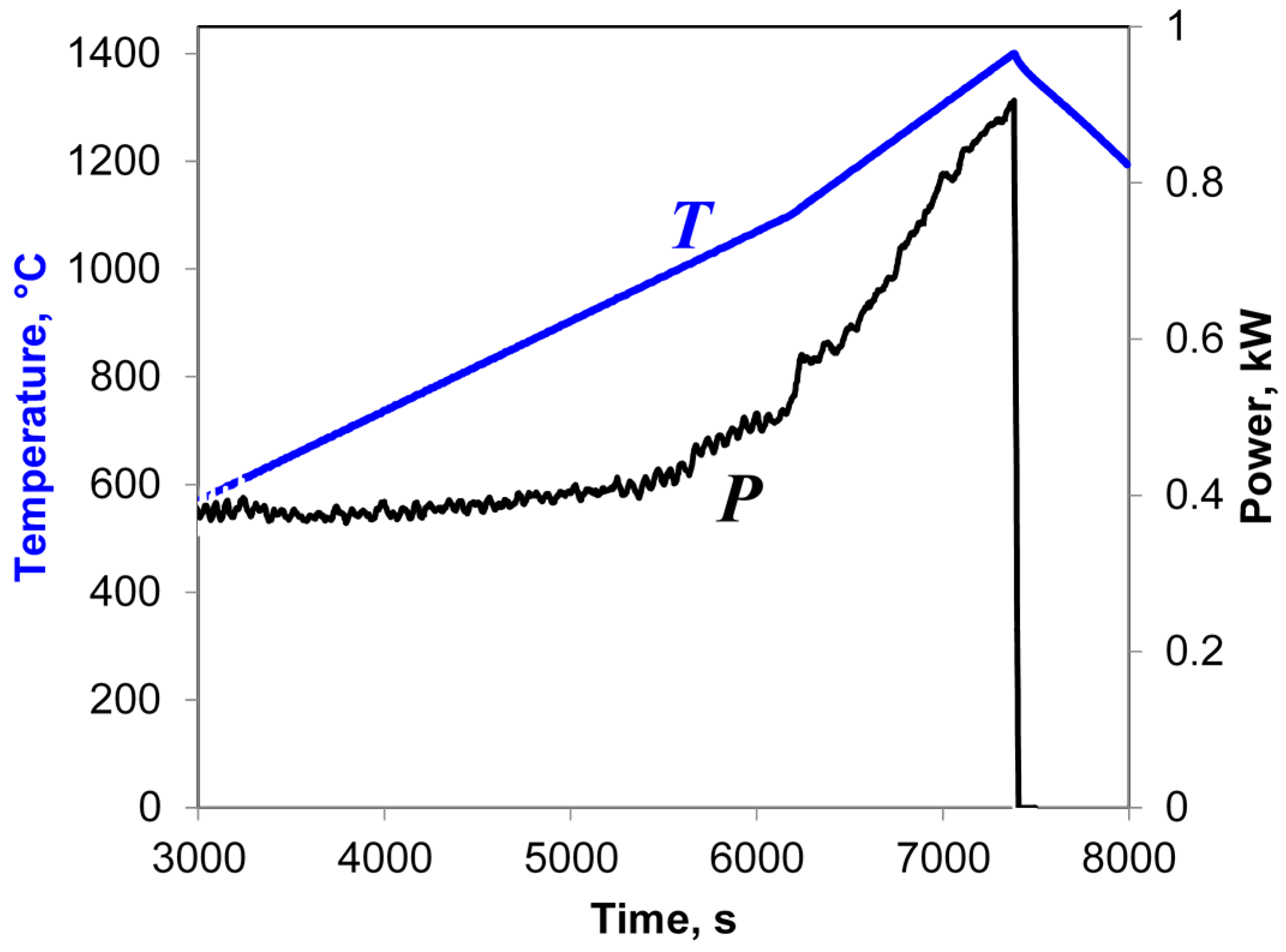
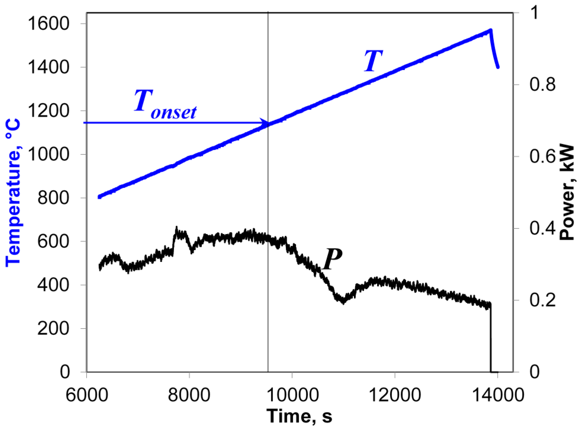
3 samples were heated at rates in the range of 50–7000 °C/min up to a preset maximum temperature chosen between 1300 and 1600 °C. The cooling rates (immediately after the automatic microwave power switchoff at maximum temperature) were 180–1000 °C/min, depending on the heating regime. An example of a typical behavior of the input microwave power,
P, during these microwave heating experiments is shown in
Figure 2.
As seen in
Figure 2, at an initial stage of heating the automatically controlled input microwave power increases from 680 to 1200 W as the temperature grows. Then, at a temperature of about 950 °C, the actual temperature growth rate begins to exceed the prescribed one. The accelerated temperature growth, i.e., thermal runaway, is suppressed by the automatic process control system by sharply reducing the microwave power. As follows from Equation (4), the drop in the power needed to sustain the heating at a constant rate means nothing but a sharp increase in the effective electric conductivity of the sample. The experiments show that the temperature
Tonset at which the power drop occurs decreases with increasing heating rate [
17]. Obviously, the observed increase in the effective conductivity must be caused by certain changes in the structure or phase state of the material, which we will identify below. Let us note that the detection of such changes based on the measurement of the input microwave power can be viewed as a peculiar implementation of the method of microwave thermal analysis [
25].
The final density of all flash microwave sintered Yb:(LaY)
2O
3 samples was 98%–99% [
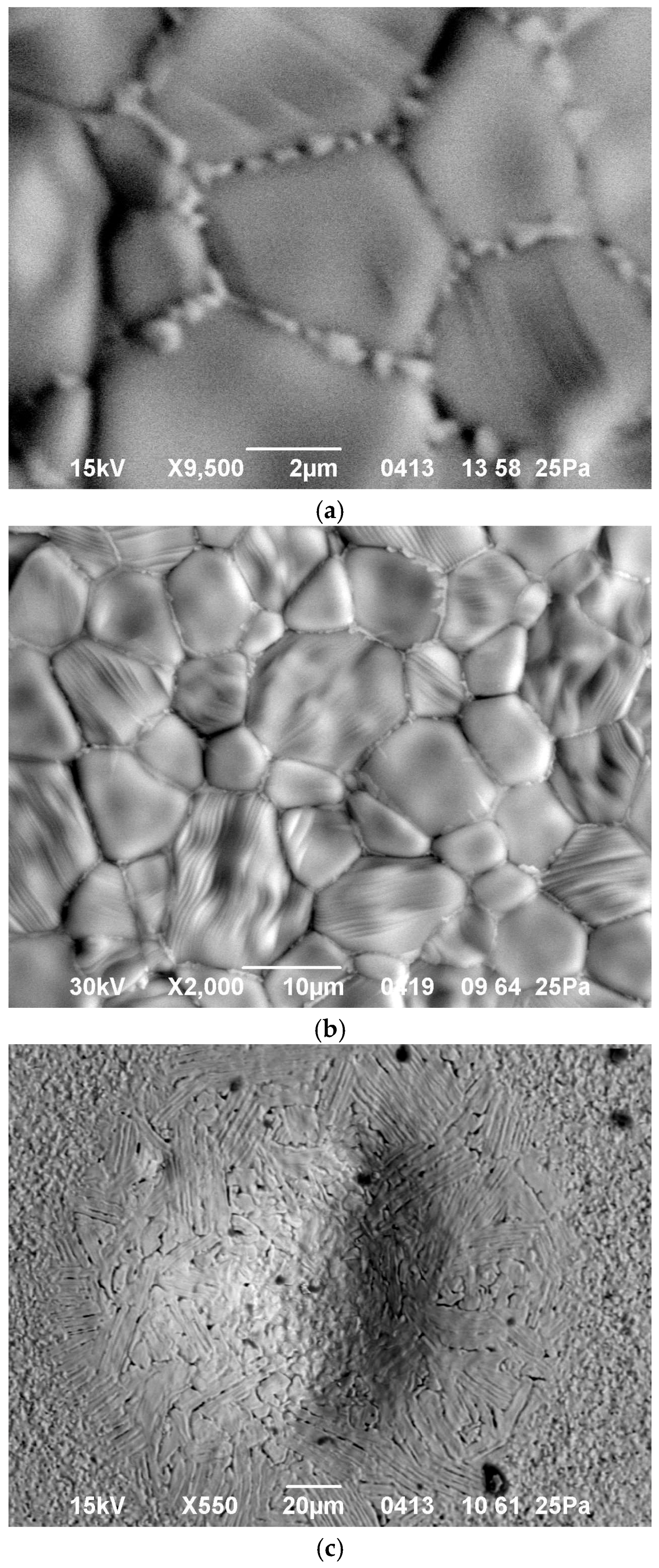
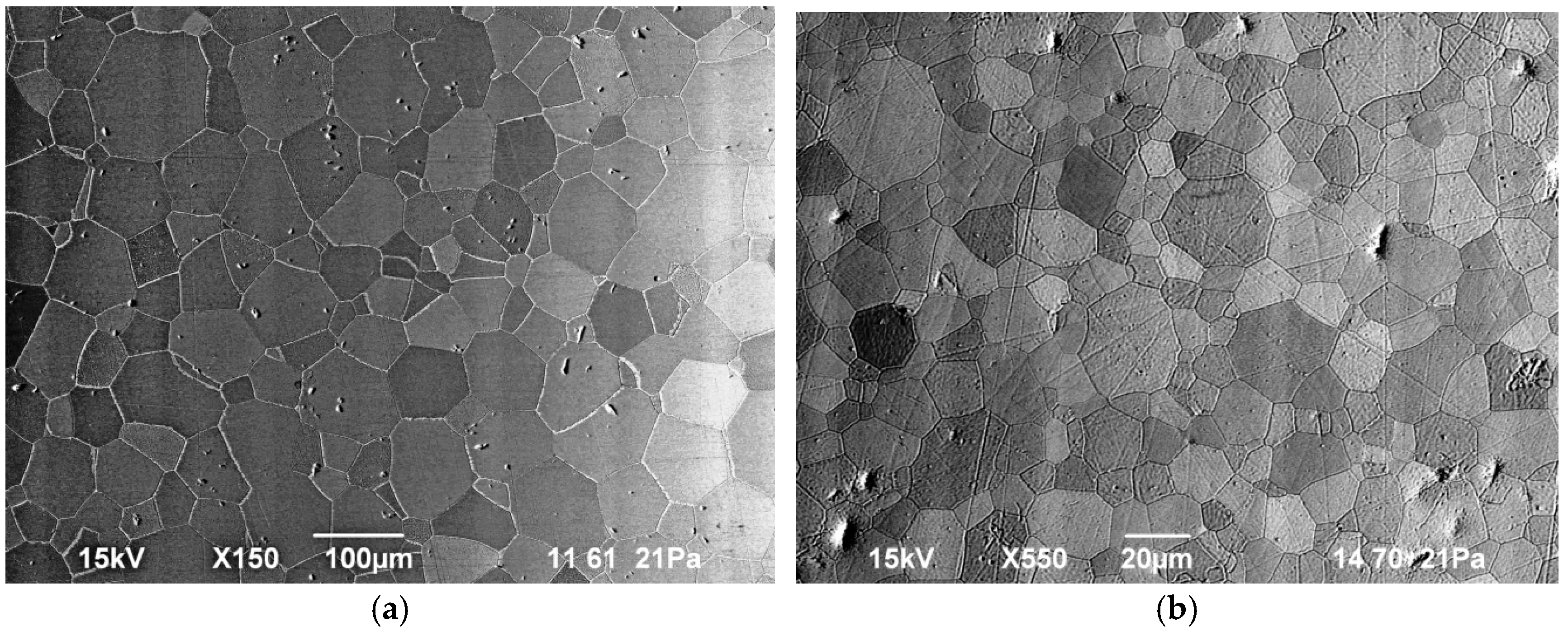
17]. An SEM study of unpolished surfaces of the samples showed that the heating rate (and hence the absorbed microwave power as discussed above) strongly affects the microstructure. Isolated droplets, a fraction of a micron in size, located along the grain boundaries are observed in the sample heated at a rate of 50 °C/min to a temperature of 1500 °C (
Figure 3a). In previous studies with samples of the same composition, microwave heated at a much slower rate of 5 °C/min [
26], no such droplets were seen in the microstructure. With an increase in the microwave heating rate to 100 and 150 °C/min, the particles merge together forming layers, up to 0.3 µm in thickness, which surround the grains (
Figure 3b). Between the grains one can clearly see interlayers composed of a different phase (looking brighter in the backscattered electron image). The formation of rounded or lenticular islands at grain boundaries that first produce a necklace structure and then aggregate into continued films is a well-known effect in the theory of liquid-phase sintering [
27].
The thickness of the melted intergranular layers varies with the heating rate and the maximum temperature of the sample. If both the heating rate and the maximum temperature were excessively high, the melting process was not confined within the grain boundaries but affected larger (though still localized) areas of the sample (
Figure 3c). An XRD study of the surfaces of all sintered samples, including those with partially melted regions, revealed only crystalline and no amorphous phases.
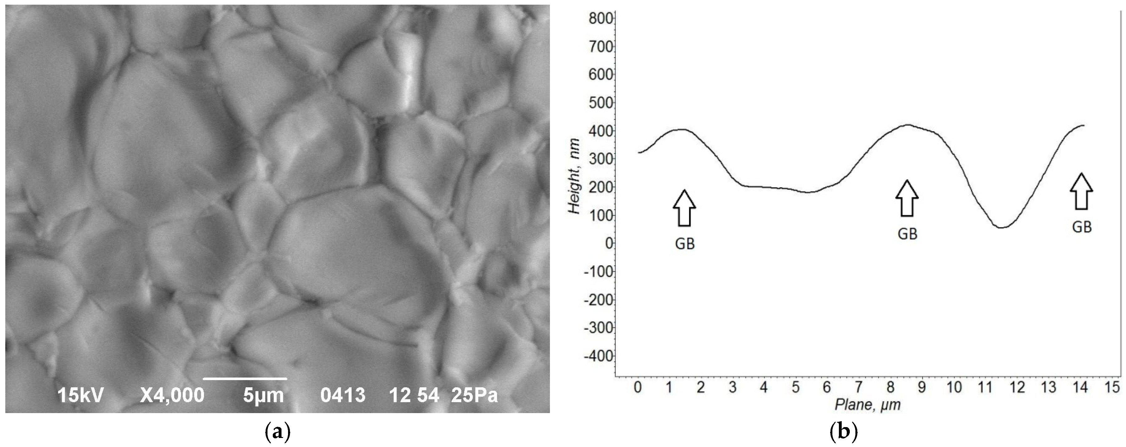
The presence of a liquid phase between solid particles was confirmed by SEM and AFM images of the surfaces of the sintered ceramic samples. For example, an SEM study of the sample microwave heated at a rate of 200 °C/min to 1500 °C showed that the surface relief is uneven on the grain size scale (
Figure 4a). The edges of the grains are raised above their middle area. The results of an AFM study of the surface relief confirmed that the grain edges are protruding (
Figure 4b). Typically, the height of these edge ledges is of the same order of magnitude as the width of the softened intergranular layers, i.e., a fraction of a micron. The protruding areas arise at grain boundaries because the volume of material changes as the liquid phase forms. In most oxide materials the specific volume increases by 10%–20% upon transition from solid to liquid phase [
28]. During sintering, the liquid phase partially fills the triple points of the granular structure by viscous flow, thus facilitating densification, and is partially extruded to the free surface of the samples.
The effect of accelerated sintering apparently results from an avalanche pre-melting or melting of powder particle surfaces [
29,
30]. The non-uniform deposition of microwave energy starts at an early stage of heating due to enhanced absorption of microwave energy at the particle surfaces, where the concentration of impurities and defects is elevated. Despite this non-uniformity in energy deposition, the temperature remains nearly uniform across the particle because thermal conductivity prevents development of a significant difference between the temperatures of the particle surface and bulk when the particle size is on the order of microns [
19]. However, due to the abundance of impurities and defects in the near-boundary regions of particles the melting temperature of surface/boundary can differ noticeably from the melting point of the pure solid material. As a result, particle surface pre-melting may occur well below the bulk melting point of the material. This leads, in turn, to a sharp increase in the effective conductivity σ
eff and the absorbed microwave power
Pv, causing the development of a local thermal runaway. Due to the melting of particle surfaces the solid grains appear to be surrounded by a melt with a low viscosity. Dissolution of solid into the liquid and enhanced diffusion mass transport through the liquid layer leads to a rounded shape and a smooth surface of grains.
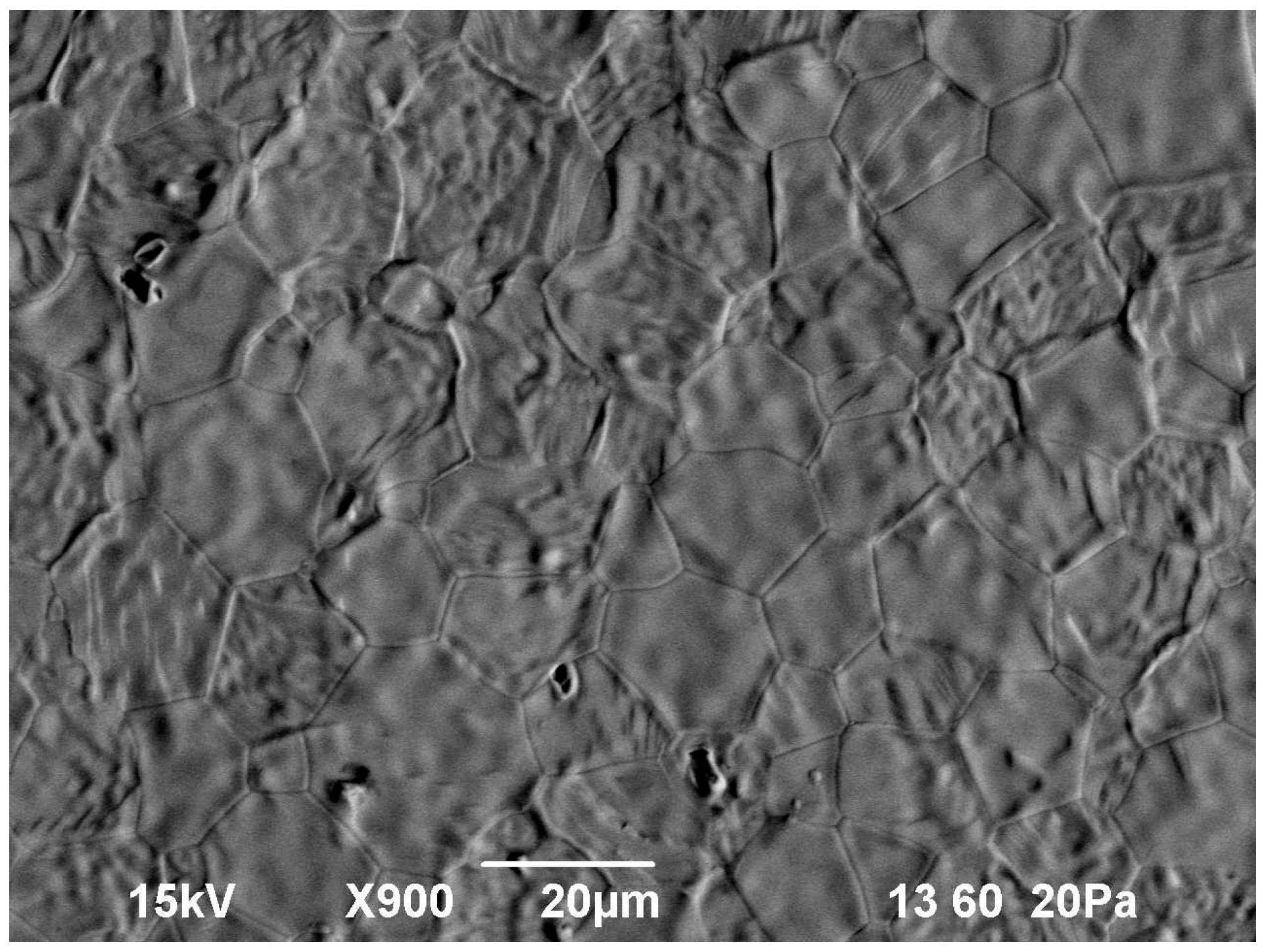
The liquid phase wets the grains completely because their chemical compositions are similar. The capillary attractive force causes particle rearrangement due to rotation and sliding of small-size grains relative to each other, which eventually results in fast densification. At the final stage of sintering the larger grains grow at the expense of the smaller grains by the solution-reprecipitation mechanism. As seen in the microstructure of an unpolished surface of a sample heated up to a temperature of 1570 °C (
Figure 5), some of the larger-size (about 20 μm) grains have an inner substructure that consists of densely packed rounded particles of an order-of-magnitude smaller size. Note that a similar microstructure, with grains having an inner substructure, was observed in the YAG ceramics sintered by spark plasma sintering [
31], which was interpreted as a manifestation of rapid densification of nanocrystalline YAG via surface softening of particles and liquid phase formation.
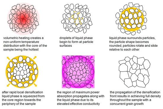
It is well known that during microwave volumetric heating, accompanied by heat loss through the surface, the so-called inverse temperature distribution develops in the sample, with the core of the sample being hotter than the periphery [
16]. For example, during microwave heating at a rate of 150 °C/min to 1500 °C the temperature difference between the center and the surface of an Yb:(LaY)
2O
3 sample with a diameter of 13 mm reached 250–300 °C [
17]. Yet, despite such a large temperature difference, the microwave flash sintered samples achieved uniform near-full density, and the grain size distribution over the diameter of the samples was fairly uniform, with deviations from the average value not exceeding ±10%. Based on the analysis of the experimental observations described above, the following mechanism of microwave flash sintering can be suggested. The process of particle surface melting starts in the core region of the sample. In the course of densification the liquid phase is partially squeezed out of the core region into the more porous peripheral structure. The region of the maximum deposition of the microwave power,
Pv, moves toward the periphery along with the liquid phase due to the elevated electric conductivity of the latter. This results in further melting of grain boundaries and liquid phase production outside of the core region of the sample. In this manner, a transient liquid-phase densification front propagates from the core of the sample to its periphery, resulting in high final density and uniform grain size distribution. It should also be noted that the liquid-phase front propagation limits the development of local thermal runaway at each particular point of the sample and thereby prevents its destruction.
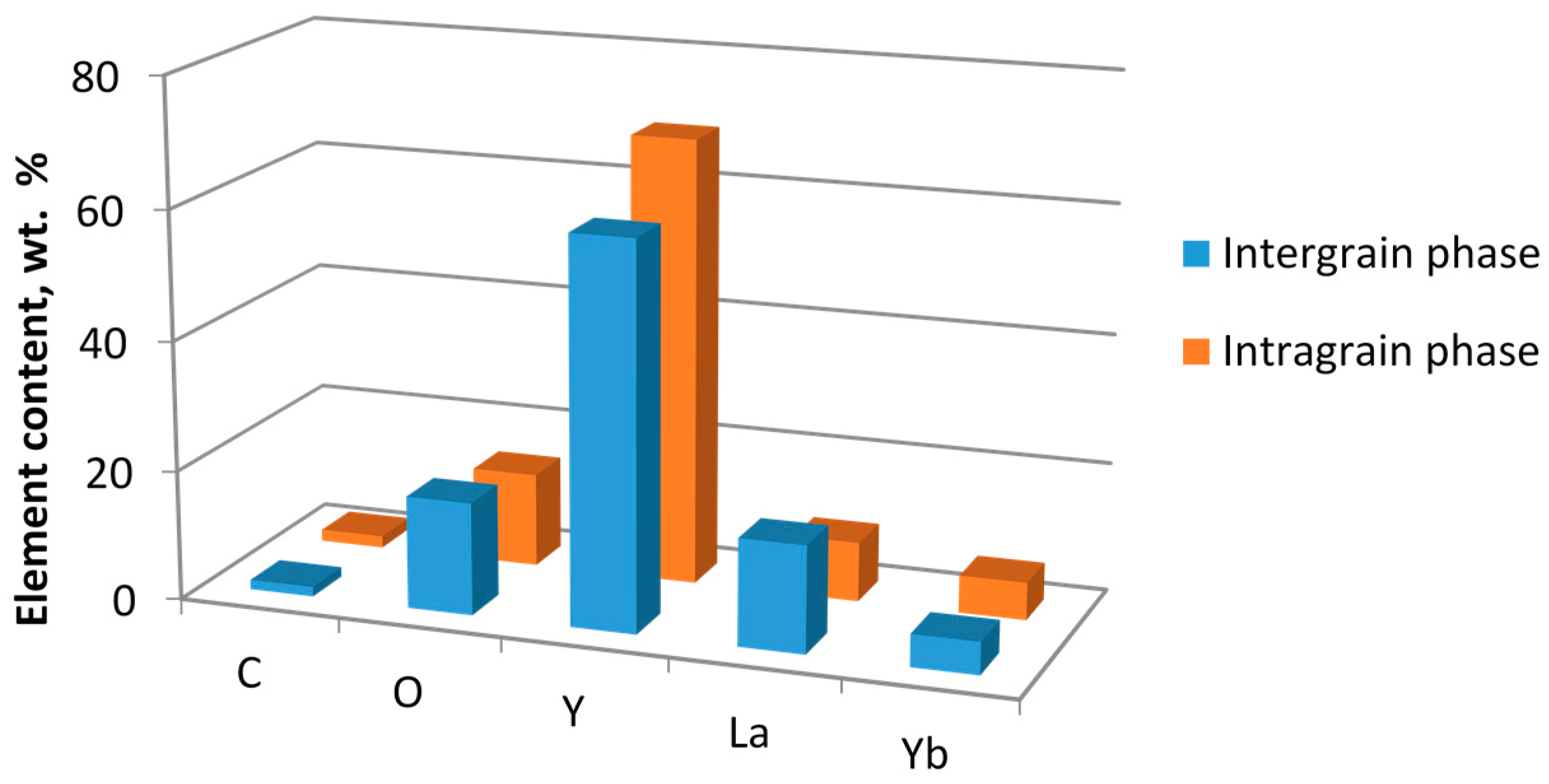
An EDX study has shown that the initially uniform element distribution corresponding to the stoichiometric compound 5 at % Yb:(La
0.1Y
0.9)
2O
3 changes after rapid sintering. The characteristic element composition of the phases was determined by averaging the results of measurements at five points belonging to the intragrain areas and seven points in the intergranular phase. Each measurement characterized a spot on the order of 1 µm in size. The measurements were performed on unpolished surfaces of the samples to increase the sensitivity to the intergranular phase that squeezed out from between the grains and distributed partially over the surface of the sample. The results of element analysis, including the values of the experimental error, are listed in
Table 1. A histogram of the element content in the intragrain and intergrain regions is shown in
Figure 6.
Compared to the material of the grains, the intergranular phase is enriched with La and O and depleted with Y. This has also been confirmed qualitatively by element maps obtained by X-ray microanalysis. The relative element content in the bulk of the grains is close to the stoichiometric ratio for the composition 5 at % Yb3+ (La0.1Y0.9)2O3; however, in the intergranular phase it is notably different. Presumably, the La3+ ions have a lower diffusion coefficient than Y3+ due to their larger mass and ionic radius; therefore La ions may accumulate in the intergranular regions.
3.2. Microwave Effect on the Grain Growth Kinetics of Yb:(LaY)2O3 Ceramics
It is known that the Y
2O
3—(0–18 mol %) La
2O
3 solid solution with a cubic structure is thermodynamically stable at temperatures above 1400 °C [
32,
33,
34]. No thermodynamic data on the 5 at % Yb
3+ (La
0.1Y
0.9)
2O
3 composition, in particular on its melting temperature, are available. In order to study the effect of the microwave electromagnetic field on grain boundary melting phenomena, liquid phase formation, and its influence on grain growth, samples of this composition were heated both by microwaves and conventionally (in a resistive oven). This experimental series was performed at a ramp-up rate of 6 °C/min to make possible the comparison between the results of microwave and conventional heating.
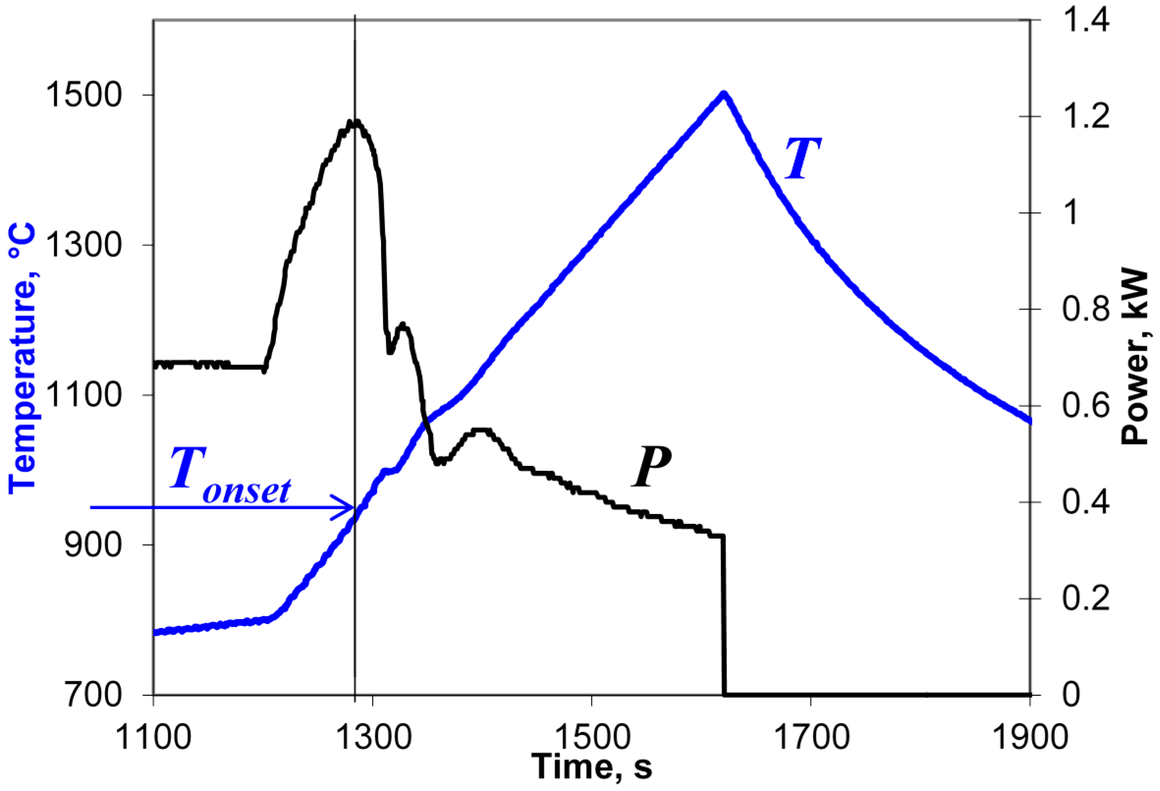
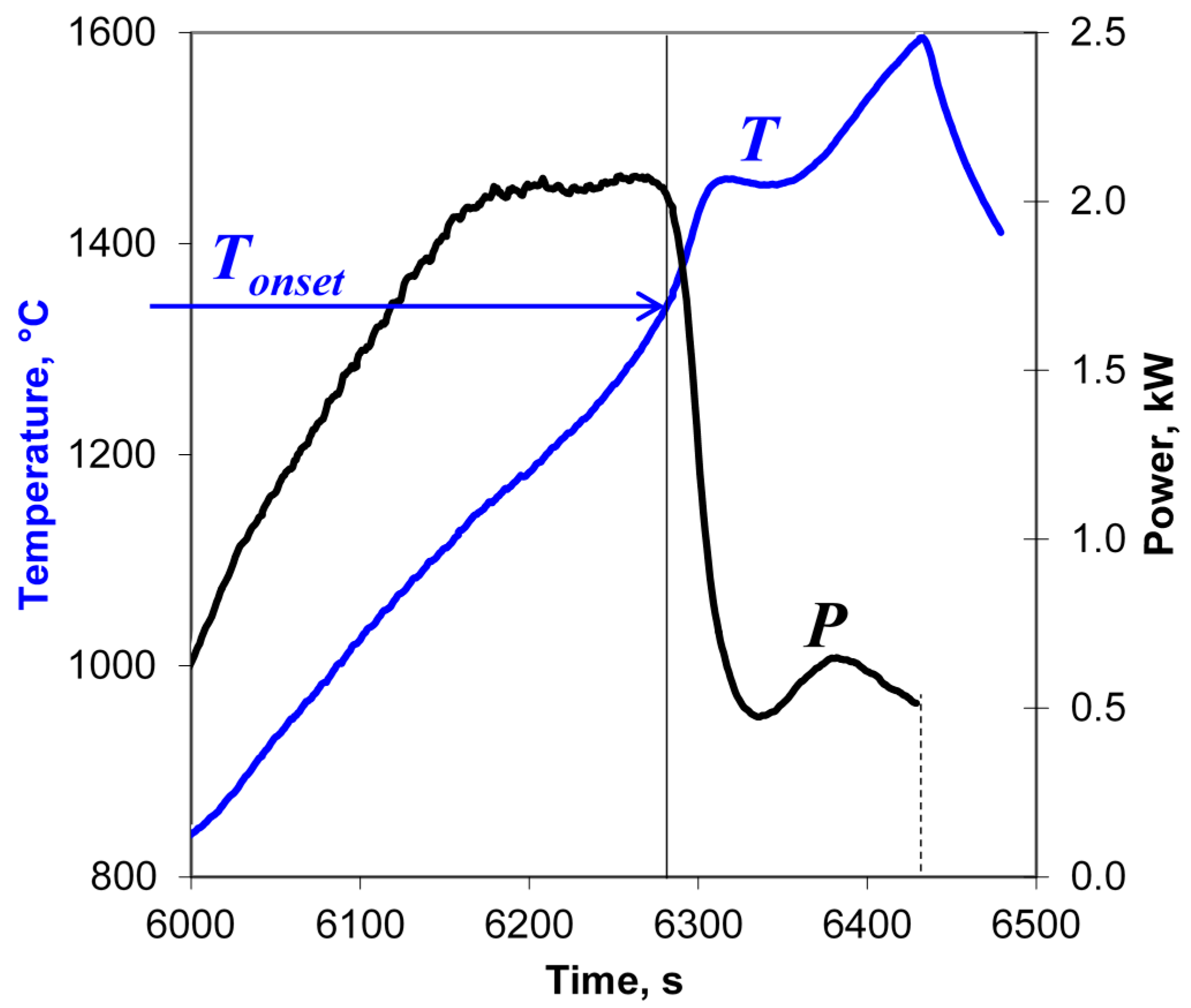
An example of a typical behavior of the input microwave power during the heating at a rate of 6 °C/min is shown in
Figure 7. The vertical line denotes the onset of the rise in the effective conductivity presumably caused by the melting of particle surfaces. At this low heating rate, the onset temperature,
Tonset, is 1140 ± 20 °C, which coincides within the margin of error with the value 1130 ± 20 °C observed at a heating rate of 50 °C/min in the experimental series described in
Section 3.1. This suggests that the temperature of particle surface softening in the presence of moderate-intensity microwave field is about 1140 °C, decreasing at higher field intensities.
It is well known that the process of grain growth is greatly accelerated in the presence of the liquid phase in the sintered material [
35,
36]. The rate of diffusion mass transport is proportional to the product of the diffusion coefficient and the cross section of the diffusion layer. At liquid phase sintering the magnitude of this product is high compared with the case of solid phase sintering due to an increase in both factors. As a result, the rates of both densification and grain growth are higher at liquid phase sintering. The features related to microwave radiation absorption and microwave interaction with the material may develop at any of the main consecutive stages of liquid-phase sintering [
36]: (a) melting of the liquid-forming additive and redistribution of the liquid; (b) rearrangement of the majority solid phases in the presence of a liquid phase; (c) densification and shape accommodation of the solid phase; and (d) final densification driven by residual porosity in the liquid phase.
Therefore, a comparative study of the grain growth kinetics should make it possible to understand the mass transport mechanisms involved in the sintering process. The grain growth was systematically studied under microwave and conventional resistive heating by varying the temperature and hold time.
The grain growth by different mechanisms of diffusion mass transport is described by the following expression [
35]:
where
D(
t) and
D(
t0) are the grain sizes at time
t and
t0, respectively,
m is the grain size exponent,
K0 is the pre-exponential factor of the diffusion coefficient,
Qa is the grain growth activation energy, and
R is the gas constant. The exponent
m depends on the rate-controlling mechanism of grain growth. The value
m = 2 indicates that the solid state mass transport is the dominant mechanism for grain growth, whereas
m = 3 is indicative of the diffusion though the liquid phase [
37] or ion dissolution as the rate-controlling step.
The average grain size was determined using the SEM images obtained on the polished surfaces of the samples. The microstructure of samples sintered under microwave and resistive heating at a temperature of 1750 °C with a 10-h isothermal hold is shown in
Figure 8.
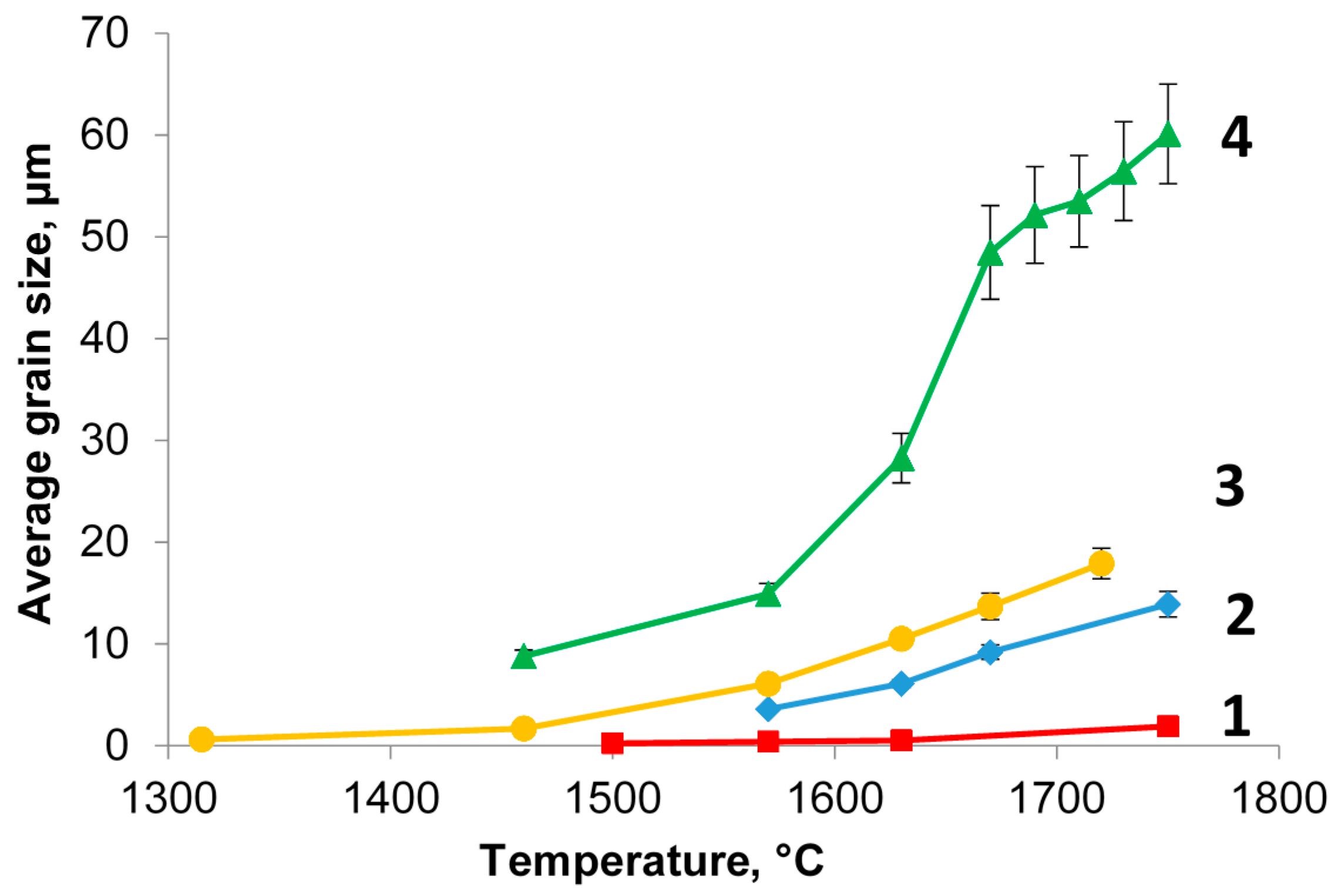
Figure 9 shows the dependencies of the grain size (averaged across the diameter of the sample) on the sintering temperature at microwave and conventional heating for zero and 10-h hold times.
As seen from the data plotted in
Figure 9, the heating method affects the grain growth rate substantially. At the same temperature and hold time, the average grain size obtained under microwave heating exceeds the grain size obtained under conventional heating greatly. For example, at a temperature of 1570 °C and zero hold the average grain size is 0.52 µm under conventional heating and 6.1 µm under microwave heating; at a temperature of 1750 °C and a 10-h hold the average grain size is 13.9 µm and 60.1 µm, respectively.
In the case of microwave heating, the character of the dependency of the average grain size on the temperature and hold time is typical of liquid phase sintering [
38]. The rapid growth of the average grain size at intermediate temperatures (1550–1650 °C) corresponds to the predominant effect of the solution-reprecipitation mechanism at this stage. At higher temperatures the grain growth slows down and the microstructure coarsening by the Ostwald ripening mechanism can become the dominant process. This grain growth slowdown is as well characteristic of conventional and spark plasma liquid phase sintering [
39,
40] and it does not depend on the method of heating.
The activation energy of grain growth can be determined on the basis of the obtained data using Equation (5). Plotted in
Figure 10 are the dependencies of the quantity ln[(
Dm(
t) −
Dm(
t0)] on the reciprocal temperature. The values of the activation energies and the coefficients of determination corresponding to a straight line fit of the Arrhenius dependence of ln[(
Dm(
t) −
Dm(
t0)] on
T−1 are listed in
Table 2 for different
m values.
One or another mechanism controlling the grain growth could be chosen based on the comparison of the obtained values of the activation energy for grain growth with the known data on the activation energy for diffusion processes in the given material in the appropriate temperature range. Unfortunately, there are no data on the activation energy for diffusion available for the Y2O3—10 mol % La2O3 (doped with 5 at % Yb) solid solution.
It can be seen from the data listed in
Table 2 that for the case of conventional heating the
R2 values for both fits (
m = 2 and
m = 3) virtually do not differ. The hypothesis of
m = 2 appears preferable because in this case the corresponding value of
Qa is closer to the typical values of the activation energy of grain boundary diffusion of Y
3+ ions in solids [
41,
42]. In the case of microwave heating, the plot of ln[(
Dm(
t) −
Dm(
t0)] shown in
Figure 10 has two distinct parts for low (1570–1670 °C) and high temperatures (1670–1750 °C). This behavior is typical of liquid phase sintering due to the different mechanisms of grain growth acting at low and high temperature. The calculated values of the activation energy differ greatly for the two parts of the plot: for
m = 3 the activation energy
Qa = 241 kJ/mol for the temperature range 1570–1670 °C and
Qa = 1056 kJ/mol for the range 1670–1750 °C. Large activation energy values for the high-temperature range are in good agreement with the activation energy for dissolution of rare-earth oxides which is above 1000 kJ/mol [
43].
3.3. Ultra-Rapid Microwave Sintering of Al2O3, MgAl2O4, and Y2O3 Ceramics
The observed flash microwave sintering effect is not unique to Yb:(LaY)
2O
3 laser ceramics. The heating procedure, conditions and characteristic features of ultra-rapid microwave sintering have been studied for other oxide ceramics: Y
2O
3, Al
2O
3, and MgAl
2O
4 [
18,
44]. Similar to the case of Yb:(LaY)
2O
3 ceramics, the occurrence of the microwave flash sintering effect was in all cases determined by the combined action of two factors: the temperature of the sample and the microwave power deposited per unit volume of the sample,
Pv. The overheating of the samples was avoided and their integrity was ensured by a system of fast automatic process control, which prevented development of the thermal runaway. From the practical viewpoint, it is important that the onset of rapid densification is easily identified without dilatometry by a sharp decrease in the level of the input microwave power required to sustain the preset heating rate.
The Y
2O
3 samples were microwave heated at rates 10–200 °C/min to maximum temperatures 1400–1700 °C with zero hold time. Both a sharp drop in the input microwave power due to an increase in the material’s effective conductivity and a simultaneous increase in the density of the samples were observed at temperatures 1350–1450 °C when the microwave power deposited per unit volume of the sample,
Pv, was above 40 W/cm
3. As an example, shown in
Figure 11 are the temperature and the microwave power at the applicator input recorded at the high-temperature stage of the sintering of an Y
2O
3 sample with a heating rate of 100 °C/min to a maximum temperature of 1600 °C. Y
2O
3 samples with densities over 0.98 ρ
th have been obtained at a heating rate of 100 °C/min and maximum temperatures 1600–1700 °C. The density of the microwave flash sintered Y
2O
3 samples was higher than the density of the samples obtained by a slower-rate (10 °C/min) microwave heating process with a 15 min isothermal hold at the maximum temperature.
The Al2O3 powder compacts were microwave sintered in air at heating rates in the range 50–250 °C/min. The microwave power deposited per unit volume of the sample, Pv, was 15–100 W/cm3. Samples, with the density as high as 98%–99% of the theoretical density (ρth), were obtained at temperatures 1400–1550 °C with zero hold time. Additionally, Al2O3 samples were sintered in a preheated resistive furnace in the regimes which mimicked the regimes of microwave heating precisely, to make possible the comparison between the results of fast microwave and conventional sintering. The density of the samples sintered in the resistive furnace did not exceed 0.96 ρth.
The density of the MgAl2O4 samples microwave heated at rates in the range 100–200 °C/min to a maximum temperature of 1800 °C with zero hold time was over 0.99 ρth. This was markedly larger than the density of samples heated at a lower rate of 6 °C/min to the same temperature with a 2-h hold time (about 0.97 ρth).
It should be noted that in contrast to Yb:(LaY)2O3-samples, the samples of all these compositions were compacted from high purity powders and contained no intentionally introduced additives, except for 0.05% MgO in Al2O3. Due to this fact, only minor amounts of liquid phase could be formed which were not clearly detectable by the analytical instruments used in this study. However, the specific behavior of the microwave power during the heating of the above listed ceramic materials, as well as the common features in the grain growth and microstructure formation suggest that their ultra-rapid densification at high values of the microwave power deposited per unit volume, Pv, resulted from the same mechanism of fast mass transport via the softened particle surfaces as in the case of the Yb:(LaY)2O3 ceramic sintering.
3.4. Similarity between Microwave and DC/Low-Frequency AC Flash Sintering
The effect of flash sintering under an applied DC/AC voltage is usually discussed in terms of the electric field strength and the power absorbed per unit volume of the sample [
4,
7,
29]. As was shown in [
17], the observed microwave flash sintering effect can be discussed in similar terms.
The energy balance Equations (1) make it possible to estimate the microwave power absorbed per unit volume of the sample using the data on the rates of heating (
dT/
dt)
+ and cooling (
dT/
dt)
− recorded in the experiments immediately before and after the microwave power switchoff. On variation of the microwave power input to the applicator from 0.5 to 3.0 kW, which corresponds to the variation of the heating rate from 50 to 2100 °C/min, the value of the power deposited per unit volume of the samples,
Pv, ranges from approximately 20 to 160 W/cm
3. Note that the electric power density triggering the dc/ac flash sintering of various oxide ceramics is typically in the range 10–1000 W/cm
3 [
4,
7,
29]. From the relationship Equation (3) between the electromagnetic energy,
W, stored in the cavity and the input power,
P, taking into account the quality factor for the applicator used in the experiments,
Q ≈ 10
4, the microwave electric field strength can roughly be estimated as
. At the mentioned variation of the input power the microwave electric field strength in the samples varies from 100 to 270 V/cm. The electric field of the same order of magnitude is typically imposed on the samples in the experiments on DC/AC flash sintering.
Using Equation (2) it is possible to estimate the effective microwave electric conductivity, σ
eff, based on the experimental data. It has been shown in [
17] that the electric conductivity of the intergranular liquid phase can be estimated based on the percolation theory [
45] assuming that it is much higher than the bulk conductivity of the grains. In particular, for the case when a sample was heated at a ramp-up rate of 2400 °C/min to 1500 °C it was estimated that the mass of the melted material could be as high as 20% of the total mass of the sample. The electric conductivity of the liquid phase was estimated to be 0.25–0.7 (Ω·cm)
−1. The high-temperature electric conductivity of the 5 at % Yb
3+ doped (La
0.1Y
0.9)
2O
3 composition is not known. However, it should be noted that the estimated values are slightly lower than the conductivity of pure Y
2O
3 above the melting point, which equals 0.9 (Ω·cm)
−1 [
46].
Thus, the values of the electric field strength and the power deposited per unit volume of the sample at which the flash sintering effect is observed are within the same ranges for the cases of microwave heating and the heating by DC/AC currents. The results of microstructure characterization of the sintered materials suggest that the mechanisms responsible for the flash sintering effect in the DC/AC electric field-assisted processes and microwave sintering are identical. The formation of isolated small, mostly rounded droplets located along the grain boundaries, similar to those described in
Section 3.1, was observed in a study of the microstructure of BaCe
0.8Gd
0.2O
3-δ powder compacts heated conventionally under an applied ac electric voltage [
6]. According to reference [
6], the ac current flowing through the grain boundaries promotes grain welding via local Joule heating.
The fact that the flash sintering effect is perhaps more pronounced in the case of DC/AC field-assisted sintering could be associated with the significant difference in the geometrical configuration of the samples used in the experiments. This difference results in a different degree of temperature non-uniformity over the sample cross section. The samples used in the DC/AC flash sintering experiments were either dog bones with a cross section about 2 × 3 mm2 or small pellets, 5–7 mm in diameter, whereas the diameter of the pellets used in the microwave flash sintering experiments described here was 13 mm.


 and
and 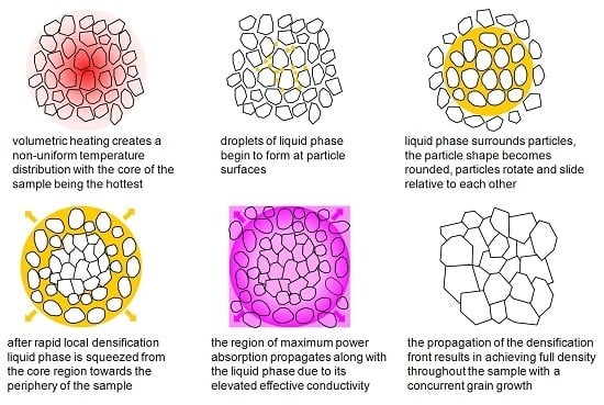


