
Integrated Conceptual Mechatronic Design of a Delta Robot
by
 , and
, and
Rogelio de Jesús Portillo-Vélez
1,2,* ,
,
Iván Andrés Burgos-Castro
1,
José Alejandro Vásquez-Santacruz
1,2 and
Luis Felipe Marín-Urías
1,2 1
Facultad de Ingeniería Eléctrica y Electrónica, Universidad Veracruzana, Boca del Río 94294, Veracruz, Mexico
2
Facultad de Ingeniería de la Construcción y el Hábitat, Universidad Veracruzana, Boca del Río 94294, Veracruz, Mexico
*
Author to whom correspondence should be addressed.
Machines 2022, 10(3), 186; https://doi.org/10.3390/machines10030186
Submission received: 25 January 2022
/
Revised: 16 February 2022
/
Accepted: 28 February 2022
/
Published: 4 March 2022
(This article belongs to the Section Machine Design and Theory)
Abstract
:In this paper, a conceptual design of a Delta robot is developed by means of a mechatronic design methodology. A fully integrated conceptual design, clarifying the recurrence of the conceptual design process using black-box/white-box analysis, is presented using the Model Based Systems Engineering (MBSE) paradigm and the SysML language as the formal modeling tool. Multiple designs proposals are then evaluated by the non-linear Choquet integral in order to choose the most appropriate according to a multicriteria requirement. For a preliminary conceptual design, structural parameters for the Delta robot are determined by defining and solving a nonlinear constrained optimization problem, which considers the kinematic model of the robot maximizing its workspace. Both the decision making and the optimization problem are integrated and automated into a common software framework for the design process, by using a standard genetic algorithm and Monte Carlo method to set the optimized conceptual design to be rendered in Computer Aided Design (CAD) software and in a physical prototype, satisfying the technical specifications.
1. Introduction
A Delta robot is a high speed, light-load parallel robot. It has relevant features such as light weight, small volume, fast speed, precise positioning, and high efficiency, and it is mainly used for processing, sorting, and packaging of food, electronics, and medicines [1]. Parallel manipulators have advantages over their counterpart serial robots, essentially because the load is shared by several links connecting the mobile platform to the base. However, parallel manipulators have small workspace and singularity problems [2]. In recent years, a considerable amount of research has been focused on the design and development of parallel manipulators (PMs) due to their advantages over serial manipulators in terms of high precision, velocity, stiffness, and payload capacity [3]. Survey studies point out the potential embedded in the Delta robot structure, which has not yet been fully exploited [4,5]. Therefore, its design remains as a challenging problem in engineering. In the following sections, we review some of the most recent and relevant contributions to the state of the art of Delta robot design.
1.1. Structural and Control Design
One of the main objectives of the Delta robot design is the development of novel kinematic and mechanical structures to render desired workspace and tasks. In this context, the optimal design of Delta Robot mechanisms has been studied for the geometric structure and control parameters to meet the task requirements and performance constraints [6,7,8,9,10]. One of the main requirements for a Delta robot is to fulfill a desired workspace; therefore, a complete analytical solution for the dimensional synthesis of 3-Degrees of freedom (DOF) Delta parallel robot for a prescribed workspace has been given in [11]. Additionally, energy optimization is of paramount importance in certain applications such as conventional stereoscopic parking equipment, [12]. Innovations have also been studied [13], where a new type of Delta robot kinematic structure with only two degrees of freedom is proposed. The developed architecture enhances the classic 3-DOF kinematic structure, which allows combinations of normal or tangential efforts at the joints or torque acting on the knee; experiments from the proposed controller show that the robot correctly performs the required application. A similar 4-DOF kinematic structure of Delta robot for micromachining applications was presented in [14]. In other relevant work, the design, fabrication, and characterization of an adapted Delta robot at the millimeter scale, driven by three independently controlled piezoelectric bending actuators, was presented in [15].
1.2. Mechatronic Design
Research studies depicted in the past section lack a formal design methodology. Therefore, in a closer approach to an integrated robot design, the following research works consider mechatronic design processes exhibiting different levels of formalism.
A modular design and implementation of a Delta robot involving kinematics, control design, and optimizing methods, was introduced in [16]. The authors focused on building a mechatronic kit for university education. A novel mechatronic development of a low-cost four degrees of freedom parallel manipulator, enhancing previous designs for a lower limb rehabilitation system, was presented in [17]. A conceptual design of a novel linear Delta robot for additive manufacturing was introduced in [18], where authors used the Quality function deployment (QFD) matrix to translate user requirements into design parameters. Then, technical specifications were evaluated to generate and select engineering solution concepts, enabling to describe the form, functions, and features robot. Finally, a dimensional synthesis method applied on design of the linear Delta robot was presented. A similar concept of a Delta robotic mechanism with single legs and rotational joints was presented in [19]; in this work, the QFD matrix is used as a methodology for conceptual design. An optimization method based on genetic algorithms is used to find the minimum dimensional parameters of the robot, considering the maximization of the useful workspace as the performance index. An interesting research proposal analyzed the application of intelligent control in a mechatronics systems, and discusses the conceptual design method of a mechatronics system based on intelligent control, [20]. A sequential mechatronic design for a bionic robotic device for upper limb rehabilitation tasks at home was recently reported, [21]. The goal of the design was to obtain a portable rehabilitation device. In a recent work, a mechatronic Concurrent Design procedure to address multidisciplinary issues in mechatronics systems that can concurrently include mechanical aspects, control issues, and task-oriented features was recently presented, [22]. This approach considers multiple criteria and design variables to set multi-objective optimization design problems. Nevertheless, an explicit mechatronic design procedure is lacking.
It is important to highlight that most of the reviewed works also use a white-box framework to render a mechatronic design procedure to achieve a concurrent design. None of those approaches consider a common integrated framework to use mechatronic engineering and decision-making tools in a synergistic approach. To the best of the authors’ knowledge, an integrated framework considering mechanical and electronic needs among all other mechatronic disciplines is missing in the mechatronic design literature, as the one presented in this work.
1.3. Model-Based Systems Engineering
The design of complex robotic systems is becoming more challenging, as a larger number of disciplines that interact in a synergistic fashion for novel applications of robotics are integrated. In this context, traditional design approaches are reaching their boundaries and need to be updated. A natural proposal to deal with this problem is Model-based systems engineering (MBSE). MBSE has been evolving for more than 20 years, with some major advances over the past 10 years [23,24]. Using the MBSE approach, the systems design can be analyzed from two perspectives: first, a black-box model, which encapsulates the system as a whole as seen from the outside, represents how the system performs when interacting with its context; then, a white-box model, where the system is seen as a set of interacting subsystems collaborating to produce the black-box behavior [25]. One of the main objectives of the MBSE approach is to meet the user’s needs as much as possible, expressed as requirements of the system in the real world, thus fitting as a natural tool for conceptual design [26].
In this paper, we address the integrated mechatronic conceptual design of a 3-DOF Delta parallel robot by means of a MBSE methodology [23,27,28] supporting both the modeling and design processes of the system on SysML [29] and relevant engineering tools, integrated into a common framework [30,31].
The main contributions of this work are summarized in the following points:
- A clarifying view for the recurrent process of black-box/white-box analysis during the design process, allowing a natural integration of multicriteria decision making tools for a mechatronic robot design;
- An integrated framework for mechatronic conceptual design considering both theoretical and numerical engineering tools such as complex decision making, automated optimization, mathematical, and CAD/CAE modeling techniques;
- An MBSE methodology that enables to capture knowledge in a systematic way from the user needs to successfully design a Delta robot in terms of requirements, functionality, design synthesis, validation, and other aspects of interest for the system itself;
- It is important to highlight that this design proposal renders a more general framework for automated design, although in this paper it is implemented for a conceptual Delta robot design.
The rest of the paper is organized as follows. Section 2 presents a general overview of the formal mechatronic methodology. Section 3 introduces the conceptual design of the Delta robot from a black-box process through a kinematic design optimization process to a white-box design via proper SysML diagrams describing the formal methodology. Finally, Section 5 closes the paper with some conclusions, rendering future wok.
2. Methodology Overview
Nowadays, since literature has poorly explored MBSE-based methodologies that consider a global perspective for systems design with all aspects to describe a multidisciplinary and integrated system, the challenge of innovation in the traditional design process for mechatronic design has become relevant.
For the Delta robot conceptual design, in this work, relevant engineering tools are integrated through the whole process in a common the framework software Cameo©, using SysML: conceptual design evaluation, black-box/white-box analyzes, physical-mathematical modeling, and design through CAD/CAE tools and specialized software for the system itself such as Autodesk Inventor©, SolidWorks©, and ANSYS©, among others.
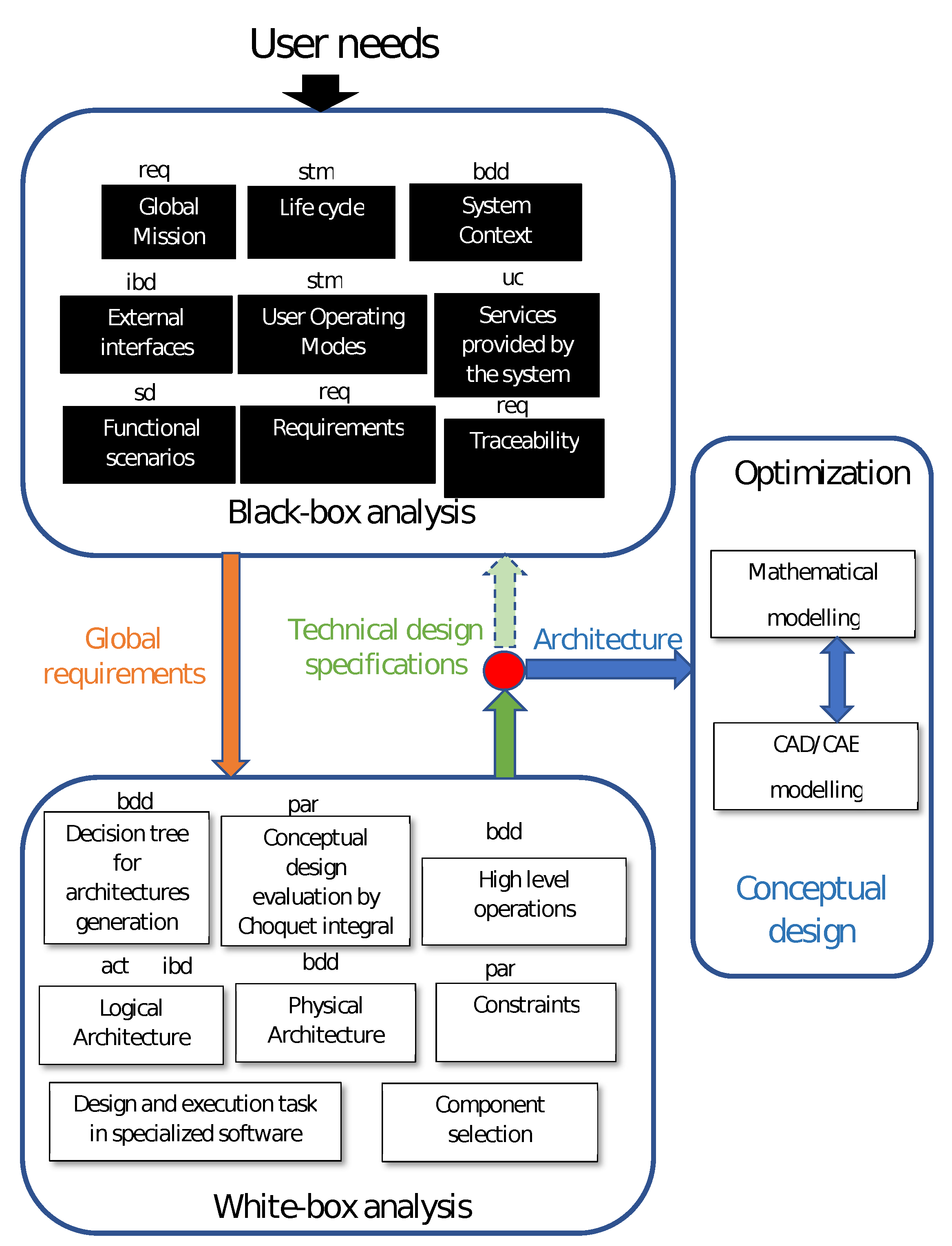
In Figure 1, a global perspective of the proposed methodology is shown, describing the phases of analysis to address the design of Delta robot. Once the stakeholder establishes the main needs and context of the problem, the process initially considers the system as a black-box. In this stage, valuable information about the system is collected and a set of technical requirements is defined in consistency with the user needs and problem definition. The output of this analysis renders global requirements for the design. This information sets up the conditions to consider the system as a white-box for deeper analysis, where conceptual architectures could be defined. This is integrated in a common software framework Cameo©using SysML as a formal modeling tool. As a result of this, a candidate final architecture is obtained, which might be considered two-fold. First, as information for a new black-box analysis; and second, as an architecture to be optimized and modeled in CAD/CAE software to render a final conceptual mechatronic design of the Delta robot. It is important to highlight the red node in Figure 1, which represents a decision step where mechatronic indexes such as MDQ [32], MDI [33], or Choquet integral [34] for multicriteria decision making might be considered. This represents a clarifying view for the recurrent process of black-box/white-box analysis during the conceptual design process. In the following sections, the design stages are described in detail (See Figure 1) for the integrated conceptual design of a Delta robot.
3. Delta Robot Design
3.1. Black-Box Analysis
The black-box analysis is addressed in order to produce global requirements from user needs to be satisfied under a general setup of the design process. This is described as follows and represents the main problem as an engineering statement to support the multidisciplinary solution to be designed.
3.1.1. Global Mission
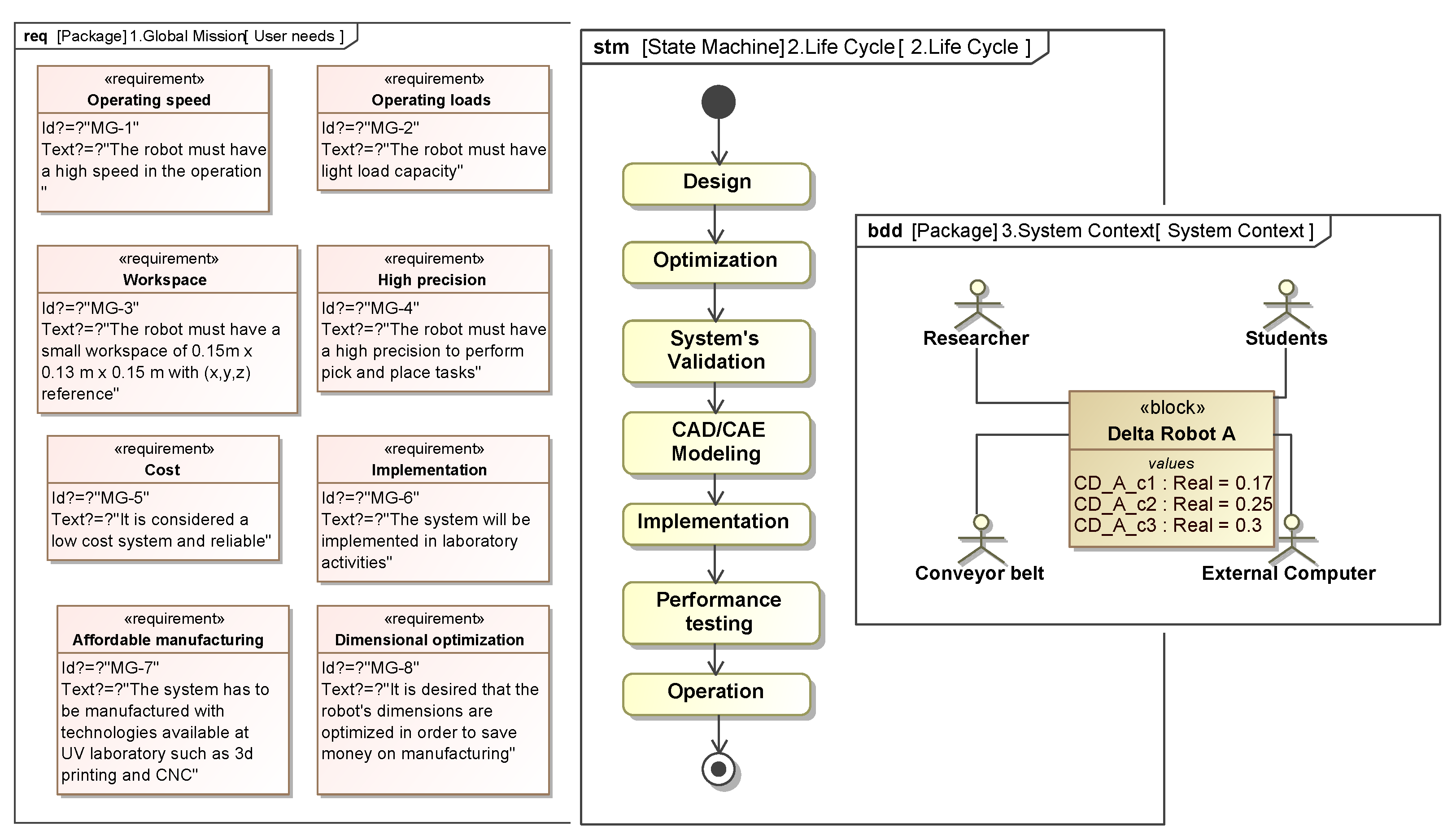
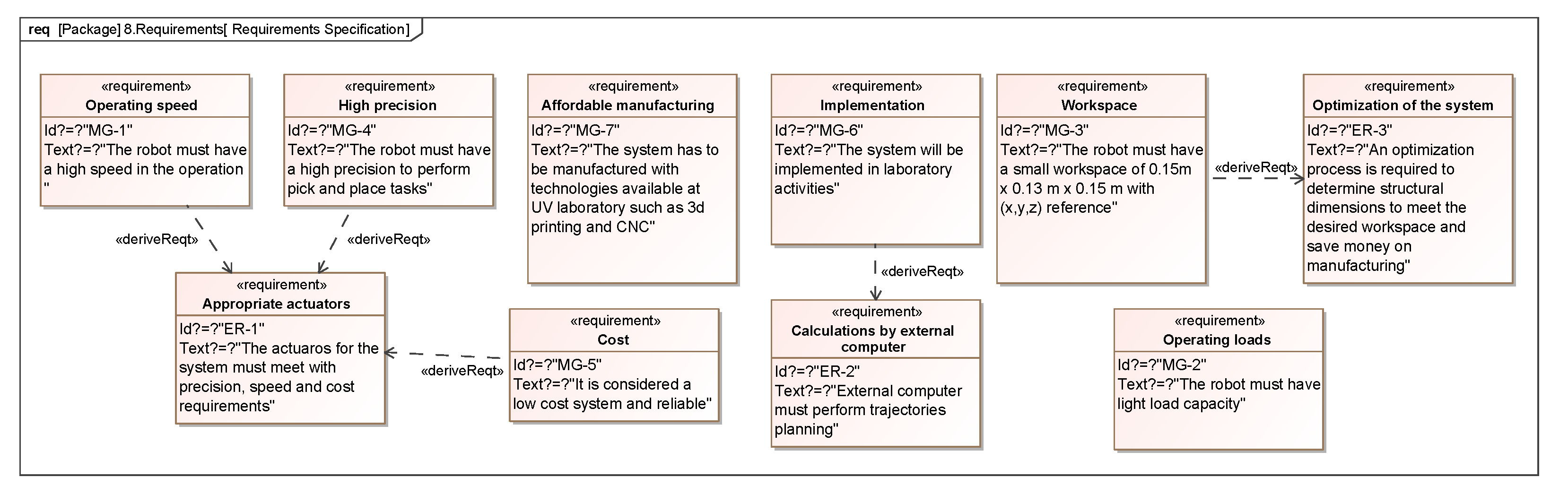
In this stage, user needs are gathered from stakeholders and the scope of what is reachable along the design process is defined. The robot system complexity is an important aspect to be considered, since different tools to address the problem are explored based on current technical knowledge and experience. As the main stakeholder requirement, a high speed and precision robot for pick and place applications from a conveyor belt at a robotics laboratory was identified. An affordable manufacturing process to produce the robot prototype is another requirement, so that the 3D printing and CNC technology might contribute to the additional affordable cost requirement. The workspace is also defined as a requirement since it is set as a prismatic volume of dimensions of 0.15 × 0.13 × 0.15 m derived from the operations to be performed by the robot. User needs are depicted by a SysML requirements (req) diagram, as shown in Figure 2.
3.1.2. Life Cycle
To develop the robot design, the black-box is defined as the life cycle of the system to define a global perspective of the project. The parameters of the Delta robot are based on the design life cycle depicted in Figure 2 (stm). The stages of the cycle are determined from team design meetings with the experience of the enrolled people in the project, supported on SysML modeling including the optimization phase, which focuses on the kinematic configuration, the system validation to guarantee the performance within the desired workspace, the CAD/CAE modelling to construct the conceptual physical architecture, and a physical implementation with performance testing for a successful operation. Note that, as only the conceptual design is addressed, the implementation, performance testing, and operation might only be virtually performed, for example by means of computer simulations.
3.1.3. System Context
The system context represents the interaction between the system and its environment. It is defined by a SysML block definition diagram, as shown in Figure 2 (bdd). Human and non-human actors are determined as operators and the conveyor belt, respectively; where the system will be performing pick and place tasks under the control external computer that will be performing different calculations.
3.1.4. External Interfaces
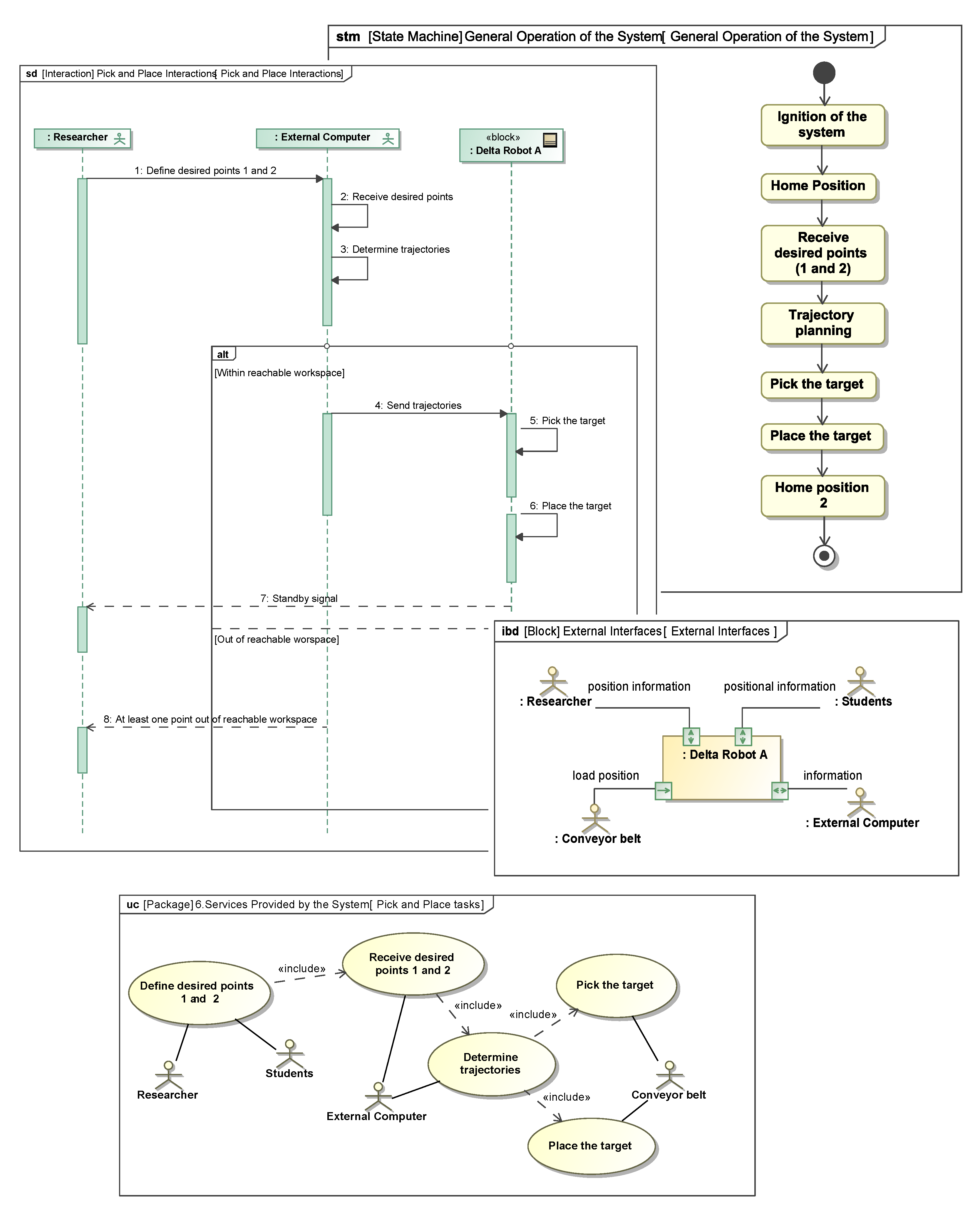
External interfaces, where the interaction variables between actors and system are determined using a SysML internal block diagram (ibd), include the direction of information flow at each port (See Figure 3). The main information for the Delta robot comes from the conveyor belt and consists of the position of the loads to pick and place, as well as the information from the external computer for the trajectories, which are translated into the joint set-points for the robot actuators.
3.1.5. User Operation Modes
Using a SysML state machine diagram (stm), the operation modes are defined for the main task of the system based on the phases established within the life cycle. Figure 3 shows the general operation: ignition of the system; go to a defined home position where motors consumes the minimal energy; receive the desired joint set-points to start trajectory planning in order to pick and place the target; and go back to the defined home position 2 to wait for the next instruction.
3.1.6. Services Provided by the System
For each operation mode, a use case diagram (uc) is defined to provide their basic functionalities. It is important to include the different actors that are present in the system context to maintain consistency. For instance, pick and place services are depicted in Figure 3. Here, actors (researcher and/or students) can define the desired robot operating points; and the receive points service, associated with the external computer actor, determines the appropriated trajectories to pick and place the loads that are on the conveyor belt actor.
3.1.7. Functional Scenarios
To perform each service of the system, a sequence diagram (sd) is the natural expression to design the interaction. For the pick and place services, for instance, Figure 3 shows how the researcher starts defining the desired points, so that the external computer receives them to determine the appropriated trajectories. From this, two possible situations may occur: the trajectory stays in the reachable workspace and is traduced to the actuators expressed in the values of rotation to pick and place the target; or it may exceed the reachable workspace and a message is sent to the user to notify the situation.
3.1.8. Requirements
According to the analysis throughout the black-box analysis, the set of requirements, first defined in common language via a requirement diagram (req), could be updated into the system context and extended to specific technical requirements to be specified (see Figure 2). This means deriving technical requirements that are needed to accomplish common language needs, as in the case of the high speed and precision requirements, from which a derived requirement is generated, called appropriated actuators, which directly affect both speed and precision variables. The implementation requirement leads to another derived requirement, which implies performing the calculations by an external computer. In addition, the requirement for the desired workspace implies the necessity to determine the optimal kinematic parameters to guarantee the ability to perform the required tasks, with respect to a desired workspace. This problem is addressed more specifically on Section 3.3.
3.1.9. Traceability
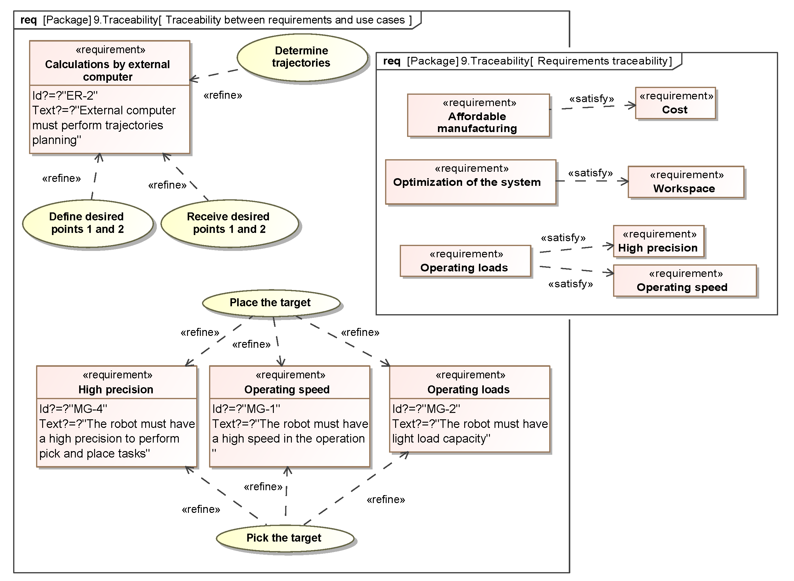
To guarantee consistency and traceability between all the final sets of requirements, the appropriated relations must be shown across the whole design process. Figure 4 shows the final set of consistent requirements, which serves as a reference to develop a detailed design, allowing both verification and validation of the solution.
3.2. White-Box Analysis
The white-box analysis emerges from the previous study, and aims to define a conceptual design to be evaluated in order to consolidate the physical architectures of the system from a logical architecture evaluation in different levels of hierarchy for the conceptual design, which implies an interacting process to concurrently define a design to be optimized in reachable space. Regarding Figure 1, in what follows, the main stages of the white-box analysis are described.
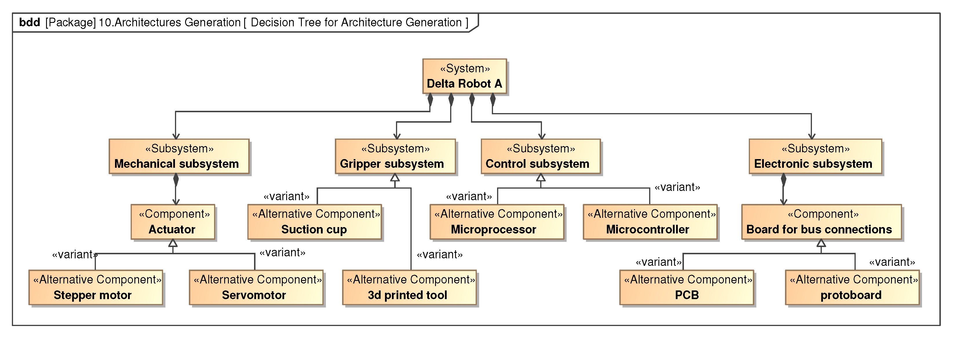
3.2.1. Decision Tree for Architectures Generation
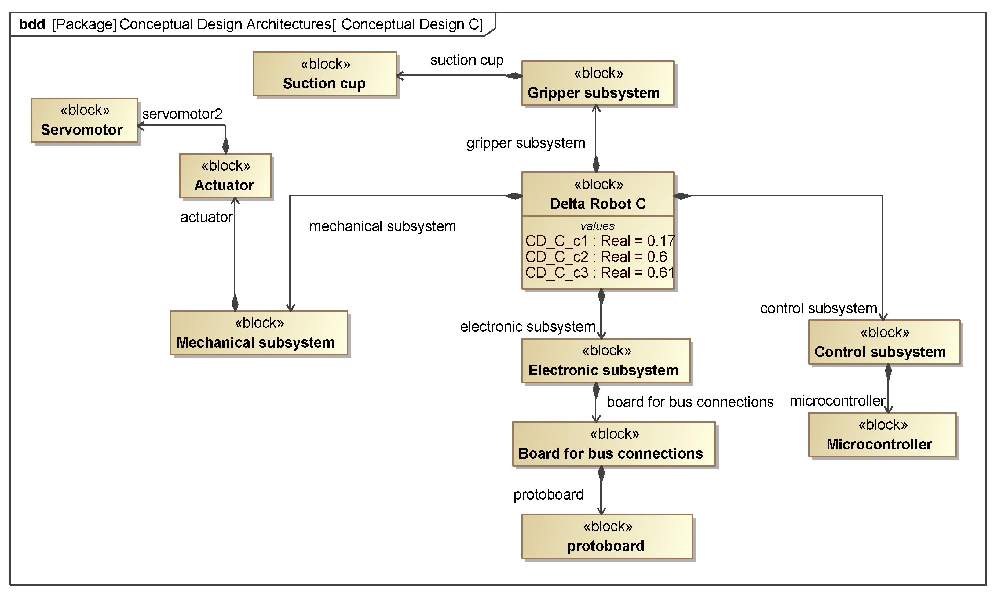
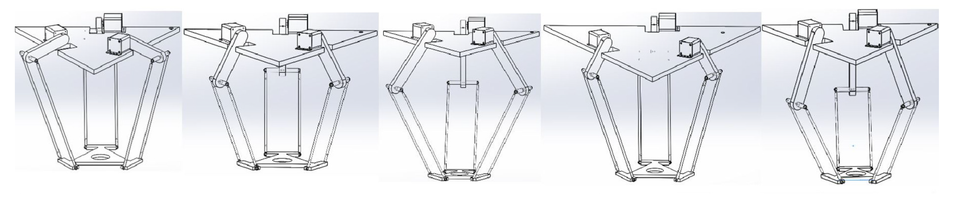
In this section, a decision tree derived from a model of variants is generated by means of a SysML block definition diagram (bdd) in order to obtain a global perspective of the possible components for the system. It used the bdd because of its structural element definitions by considering the <<alternative component>> stereotype for each subsystem, where a decision is evaluated. In Figure 5 a decision tree with stereotypes describing different level of hierarchy is depicted, where the alternative component is set to be evaluated based on the final set of requirements shown in Figure 6. Based on technical knowledge of the design team and supporting this with previous information obtained in black-box analysis, multiple conceptual designs can be obtained from the variants, as those depicted in Figure 7, Figure 8 and Figure 9 for A, B, and C candidates, respectively.
3.2.2. Conceptual Design Evaluation
The previous conceptual architectures are evaluated based on the Choquet integral, as in [35], with the main design criteria defined by dependability, cost, and complexity, in consistency with the set of final requirements determined in the black-box analysis shown in Figure 6. This represents the red node as a decision stage shown in Figure 1.
The Choquet integral is the method for multicriteria decisions to determine the optimal conceptual configuration and it requires the definition of weights as fuzzy measures assigned [34]. Table 1 expresses the main differences in the components of the different conceptual architectures to support the designer in the weights definition.
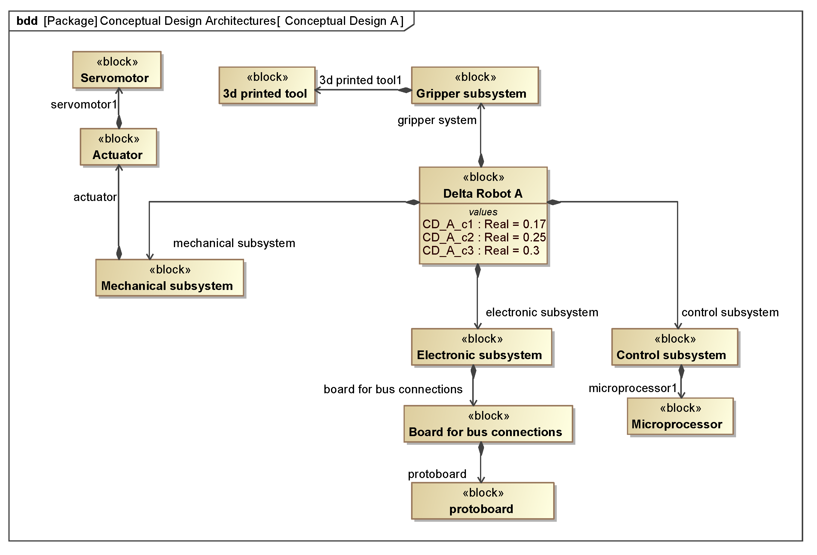
In this case, X = {dependability, cost, complexity} the set of criteria, the weights for individual and correlated criteria are defined as: (0) = 0, (dependability) = 0.4, (cost) = 0.35, (complexity) = 0.25, (dependability, cost) = 0.85 > 0.4 + 0.35 (favorable), (dependability, complexity) = 0.5 < 0.4 + 0.25 (redundant), (cost, complexity) = 0.45 < 0.35 + 0.25 (redundant), (1) = 1. This information is defined in the modeling tool, as shown in Figure 7, Figure 8 and Figure 9.
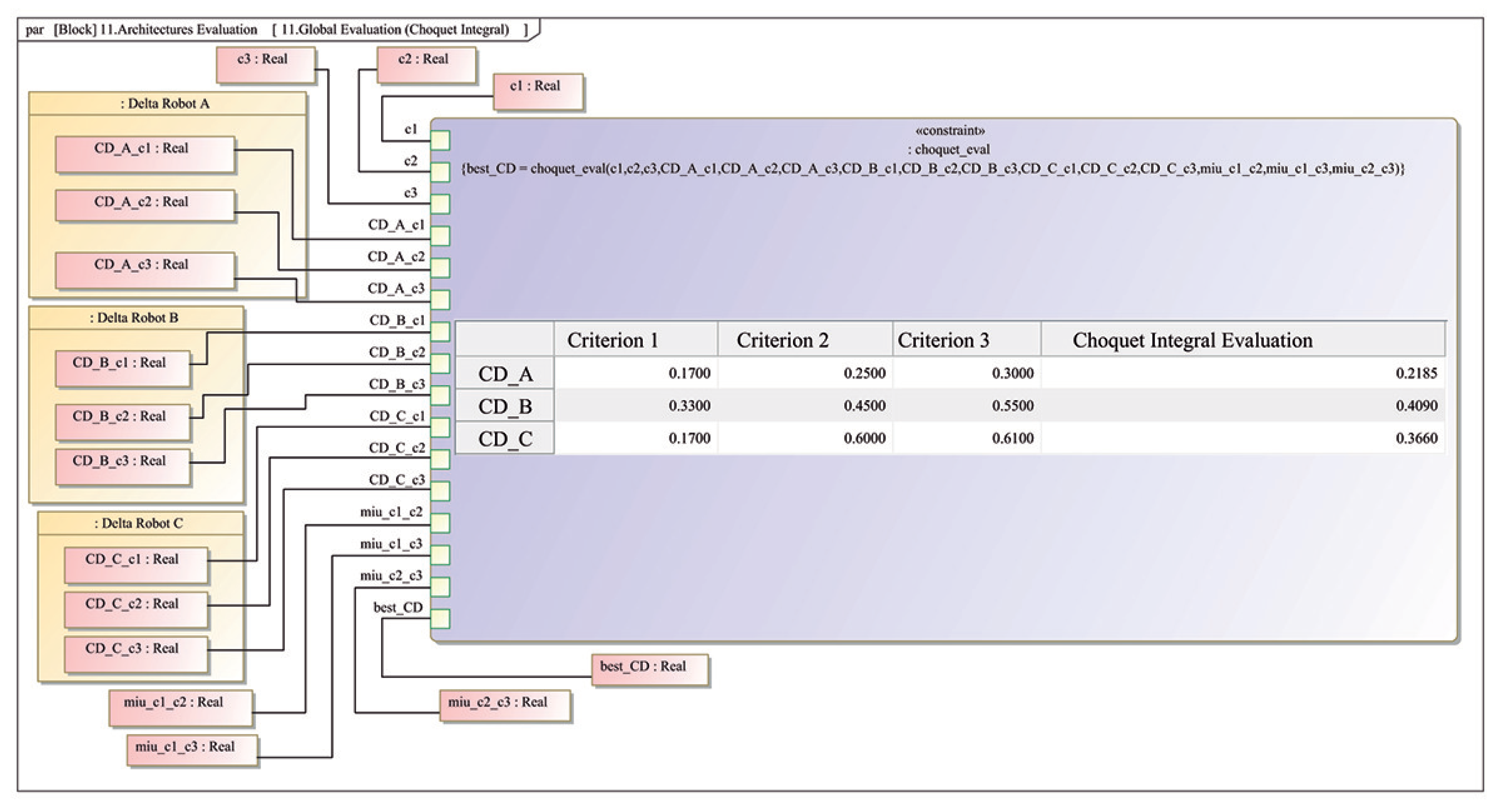
The conceptual design evaluation by means of the Choquet integral and a parametric diagram is implemented within the modeling tool, as seen in Figure 10 (par), where an automatic decision making is performed from predefined fuzzy measures and the results are displayed in an inner table, also depicted in Table 2, allowing the analysis of different scenarios, as a consequence of the design criteria parameter variations.
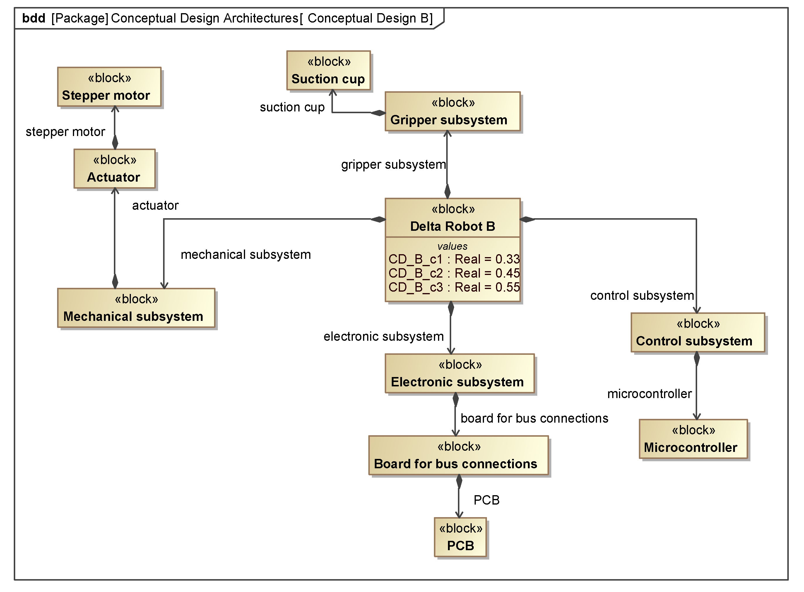
According to the conceptual evaluation for the Delta robot, the configuration that best meets the desired criteria is the conceptual design B, with the highest score. This result is a natural consequence of the set criteria weighing, favoring the correlation between dependability and cost by assigning a greater score than the sum of the individual weights of dependability and cost. Conceptual design B has a better weighting in those aspects due to the fact that stepper motors present characteristics of higher precision rather than servomotors, and the cost is determined as being lower by considering that stepper motors and the suction cup are available in laboratory, as well as when manufacturing a CNC machine.
3.2.3. High Level Operations
Based on the sequence diagram defined in the Functional scenarios Section, system must be able to perform the high-level operations according to the services defined in black-box analysis in consistency with the final set of requirements determined in the first design stage. Thereby, the Delta robot has to be able to receive the desired Cartesian pick and place points, then determine the appropriate trajectories, and send those trajectories in order to pick and place the target, which are defined as operation properties in the Delta robot block, as shown in Figure 11.
3.2.4. Logical Architecture
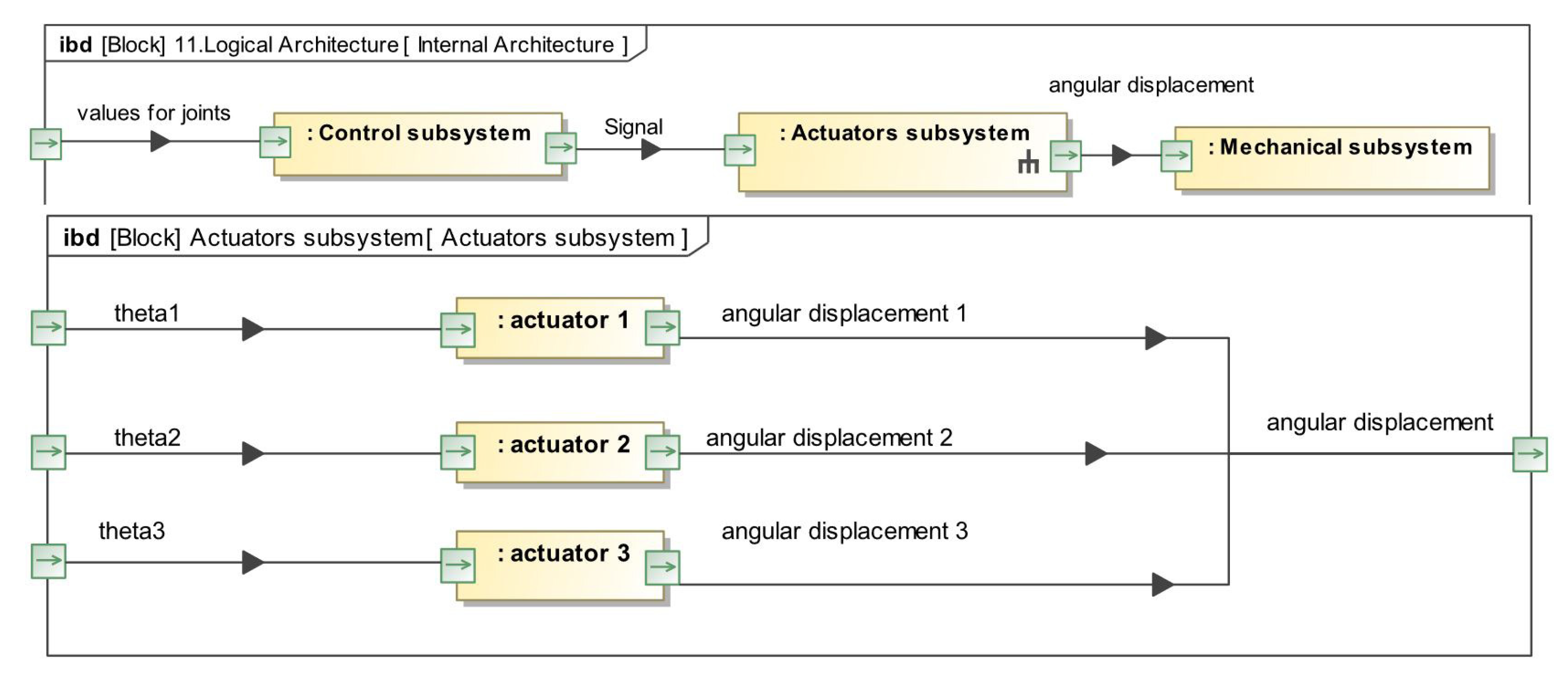
Since the system is considered in this stage as a white-box, from the high-level operations, different conceptual perspectives for the design determine a logical architecture, to be internally addressed by means of internal block diagrams (ibd) in different levels of hierarchy. Each subsystem must be modeled at a logical level by considering the components and its interaction by wires, joints, or data buses. These representations should be as close as possible to the system in the real world (see Figure 12 (ibd)).
3.2.5. Physical Architecture
For physical architecture, the analysis performed in logical architecture provides a base to determine the different components that integrate the system as a refinement of the conceptual design B, which is the selected proposal according to the Choquet integral evaluation. This analysis includes several components and devices among its compatibility to provide logical and physical functionality to the system, including actuators and sensors, among other devices.
3.2.6. Constraints
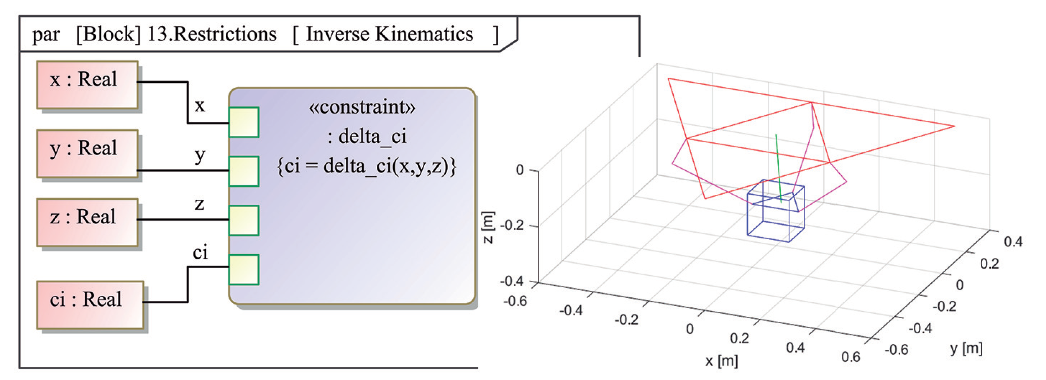
Constraints are helpful to express different aspects that best describe the system or the task to be performed by the robot. Constraints are defined through mathematical models via a parametric diagram (par) in SysML, which involve variables of interest. For example, as depicted in Figure 13, the kinematic model of the Delta robot provides a constraint for the system in order to perform a pick and place task within the desired workspace.
3.2.7. Design and Execution Task
According to the behavior defined in the High level operations, specific tasks should be designed and verified by means of different simulations in specialized software. For instance, Figure 13) depicts a Matlab© simulation of the Delta robot kinematic structure.
3.2.8. Component Selection
Though this work is focused on a conceptual design, some high level components can be deduced to provide the required performance in consistency with the physical architecture and future implementation. Table 3 shows a list of components for the Delta robot physical realization. A physical prototype of the conceptual design of the Delta robot is described in Section 5.
3.3. Optimization
After the white-box analysis, a conceptual design architecture is rendered (see Figure 1). Nevertheless, an optimization process can now be performed. In this paper, we focus on the kinematic parameters for the Delta robot, which must be determined to meet the desired workspace defined by the user requirements (see Figure 2). This can be achieved with an optimal mechanical architecture from the white-box analysis. This refinement is developed by using a standard genetic algorithm with Matlab©, to solve a nonlinear optimization problem, which maximizes an objective function described by a prismatic workspace, see Figure 14.
It is important to highlight that a more general and detailed optimization process might guarantee different optimal designs based on different criteria; such as mechanical stress minimization, energy consumption, and singularity avoidance, among others. This will lead to a multi-objective optimization problem. However, to simplify the optimization stage, a single objective function is considered. To achieve the workspace requirement, it is clear that kinematic relations are fundamental to determine the arm lengths of the Delta robot. Thus, the Delta robot workspace is defined as an objective function. The workspace has infinite reachable points by the Delta robot, therefore the Monte Carlo method is used to choose a representative subset of such points [36]. Here, the objective function is defined by:
where represents the number of points within the reachable workspace, is the total number of random points generated, and V is the volume of the desired workspace in m. This objective function is evaluated in the genetic algorithm, and the Monte Carlo method verifies if each random point generated is inside V with the inverse kinematic model of the Delta robot, rendering different kinematic architectures as depicted in Figures 15 and 16. In this study, . The design vector for the optimization algorithm is defined as
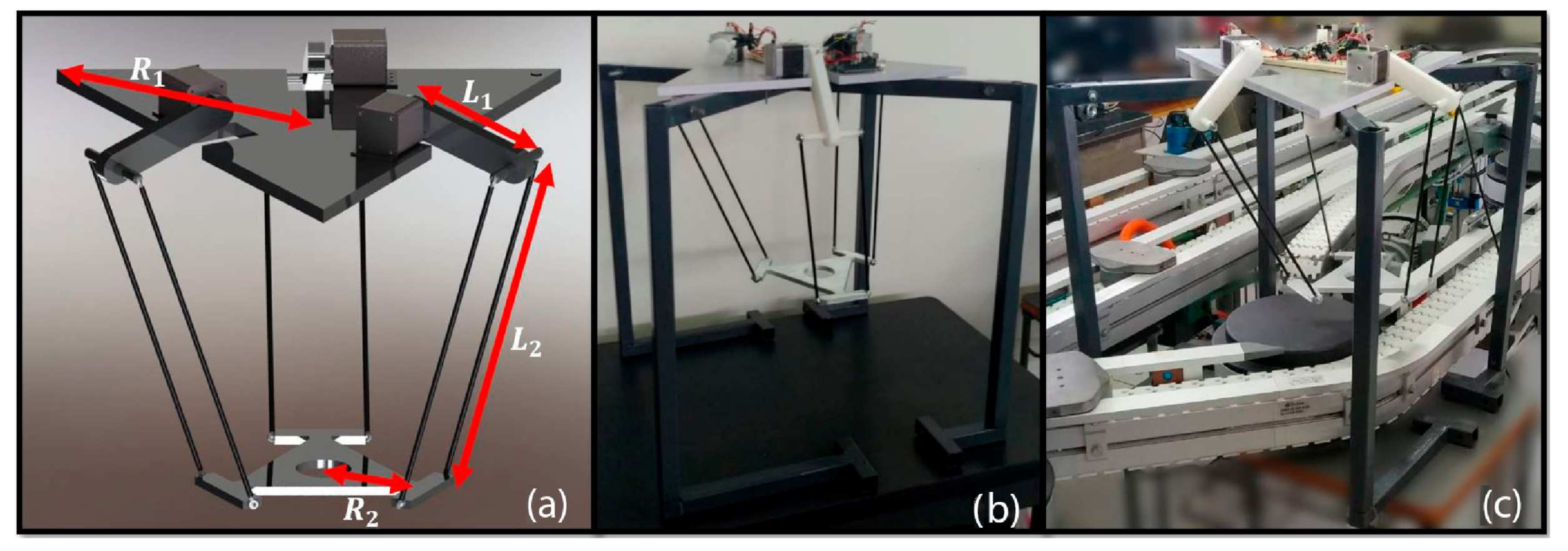
where, as seen in Figure 17, is the fixed base radius; , the mobile base radius; , the bicep length; and , the forearm length. Based on the physical station where the robot will operate, the design vector parameters are constrained: , 0.2 m m, 0.1 m m, m, 0.2 m m, 0.07 m m. After running the genetic algorithm to find a feasible region of solutions, 27 simulations are performed according to the following testing parameters for the optimization algorithm: , , ; where N is the number of randomly generated individuals, is number of generations, and is number of individuals in the population of the genetic algorithm. From those simulations, five or them are selected based on the stability of the solutions, i.e., there is less variability in the found solutions; some numerical results are presented in Table 4. The multiple simulations for different parameters could imply time in the design process, and this is why a numerical tool is integrated to the SysML model to automate the optimization process.
Tools Integration
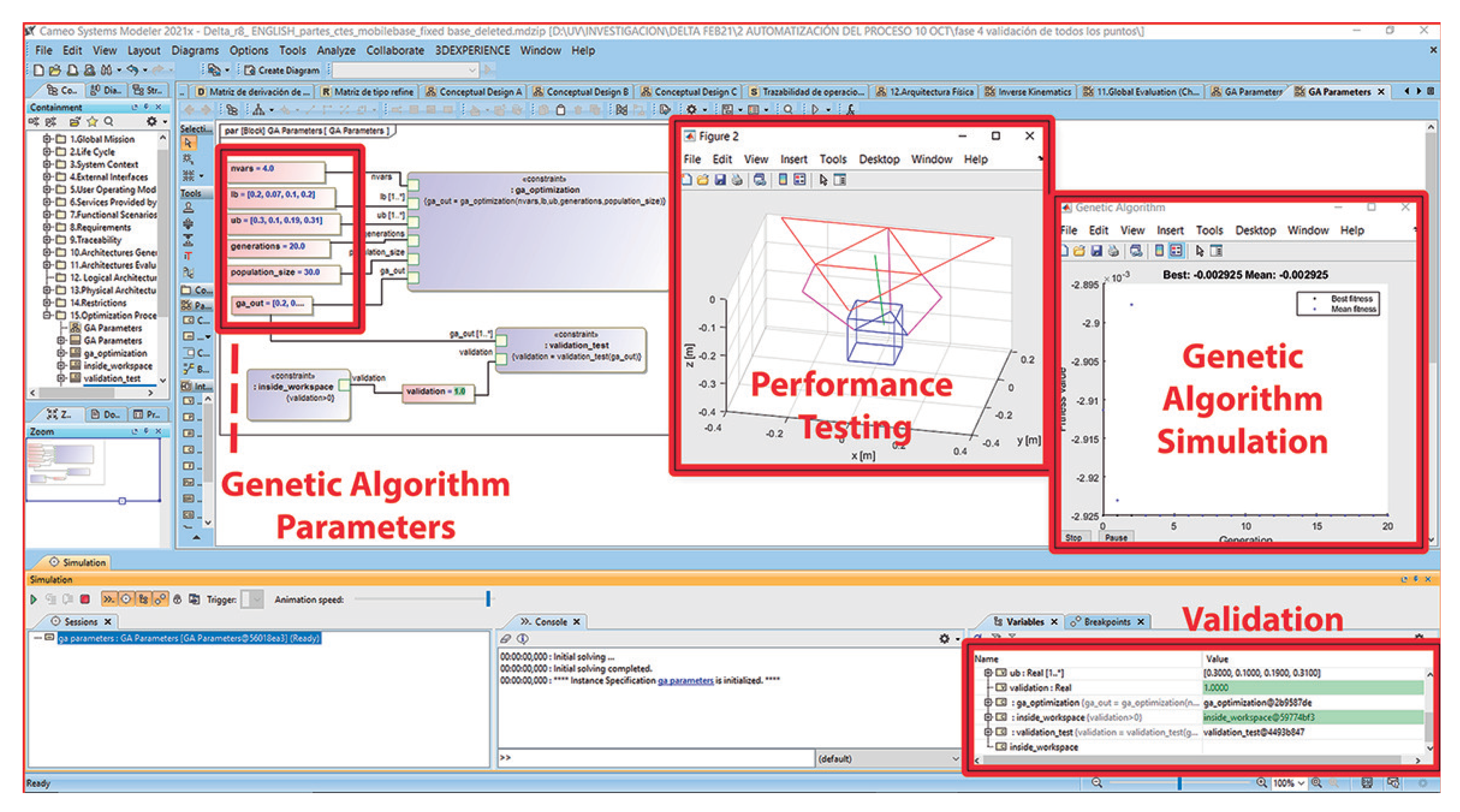
After the optimization problem is programmed, it can be merged in the common software framework using a SysML parametric diagram (par) integrated with Matlab© for co-simulation purposes. The genetic algorithm is processed in Matlab©, once the designer has defined the genetic algorithm parameters and started the simulation in Cameo©, as depicted in Figure 14. As a validation stage, it is important to remark that this integrated model also includes the multicriteria decision-making based on the Choquet integral to define the best architecture according to the mechatronic design requirements, as already depicted in Figure 10. Moreover, in this integrated framework, the inverse kinematic model is included, which serves as an evaluation of both the required joints performance and the structural parameters of the architecture, from random spatial coordinates. If an optimized architecture by the genetic algorithm does not satisfy this evaluation, then it is omitted and continues with the next one, allowing to explore even hundreds of feasible architectures that guarantee to perform their tasks in the required workspace. Therefore, in this design framework, the designer only enters and updates parameters to visualize the results for making specific decisions.
4. Validation of the Optimized System and Discussion
For the sake of validation, 13 points located around the corners and faces of the Delta robot design workspace were proposed to evaluate the performance of each optimized conceptual kinematic architecture. The results showed that architectures of simulations 20, 25, and 27 were not able to reach all the validation points while architectures 8 and 22 reached all of them. In order to choose a final conceptual kinematic architecture, a secondary criteria can be chosen by the designer. In this study, the secondary criteria is energy consumption. Simulation 8 renders shorter bicep lengths , which require less torque by the actuators and therefore, the architecture determined by simulation 8 is selected as the final optimized architecture. In general, this last study might lead to a multi-objective [6] or bi-level optimization problem, which can be approached by state of the art algorithms, [37]. Figure 15 shows the final optimized architecture, reaching different strategic points within the desired workspace.
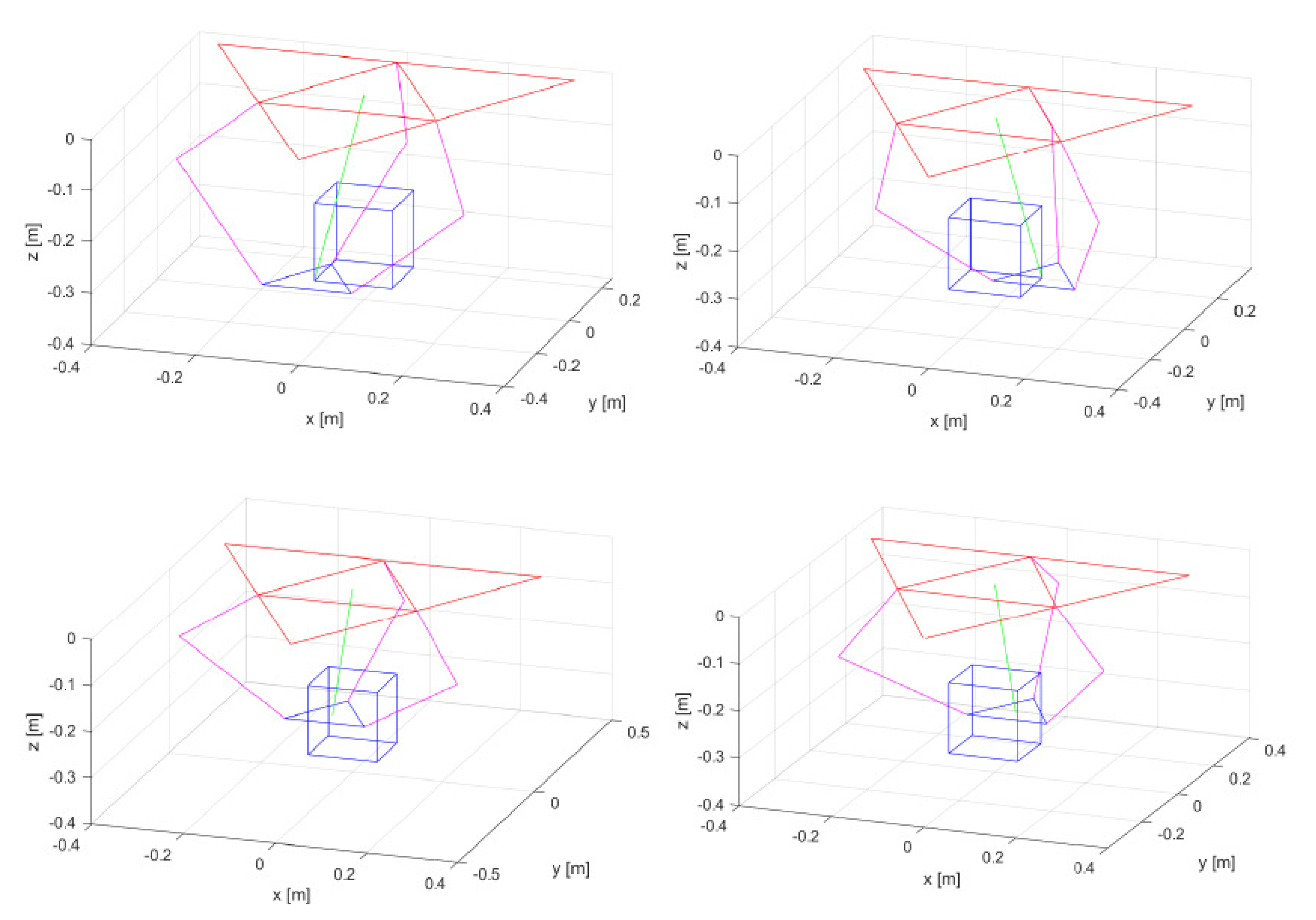
Note that the five optimized architectures also exhibit significant differences among them, as shown in Figure 16. Figure 17a shows a CAD-rendered perspective of the final optimized architecture in detail.
4.1. Prototyping
As the manufacturing is out of the scope of this paper, as depicted in Figure 1, a rapid prototype was built (see Figure 17b) considering the components selection shown in Table 3. The manufacturable parts, as in the case of the mobile base, fixed base, elements to fix actuators, biceps, and forearms, were built using 3D printing technology in PETG material, since it presents good mechanical characteristics and ensures to meet both the affordable manufacturing and cost requirements, as established in Figure 6 (req). The PCB design was not performed, because the objective of this Delta robot prototype is to quickly validate the kinematic motion of the robot within the desired workspace, according to the simulation results, reaching all the points shown in Figure 15, and mounted on the conveyor belt, as depicted in Figure 17c.
4.2. Discussion
The approach for a conceptual mechatronic design introduced in this work considers the user needs, as well as the mechanical and electronic needs among the most relevant mechatronic disciplines. From the methodological point of view, our proposal renders a concurrent design framework, integrating engineering design tools, complex decision making, and optimization. Moreover, the design framework allows for automated conceptual design optimization, which is a remarkable difference from other approaches for Delta robot design. Table 5 presents a comparison of the main features of the proposed design framework versus some of the most similar works to ours.
5. Conclusions and Future Work
In this paper, we address the formal mechatronic design of a Delta robot implementing black-box/white-box analyzes within the MBSE approach using SysML. One of the main contributions of this article is the integration of different tools into a centralized design model, as the non-linear Choquet integral, to perform conceptual design evaluations, providing the designer the most appropriate configuration according to the desired criteria. This clarifies the recurrent process between black-box/white-box analysis to render a conceptual design. Moreover, stating an optimization problem, based on the output of the multi-criteria decision making stage, allows to automate the conceptual design methodology proposed in this work. Therefore it is possible to obtain optimized conceptual systems in terms of the requirements the systems were designed for, in contrast to the systems that are designed only by means of traditional design approaches, thus offering a global and optimization-based perspective to address the design of a mechatronic system.
Thus, future work is focused on the extension of the methodology to other mechatronic systems in order to confirm the effectiveness of the application of the proposed methodology. Dealing with multi-objective optimization, a multi-level optimization integrating complex decision-making in a common framework is needed to make the optimization process more general, since most of the real-world problems demand to optimize more than one objective function.
Author Contributions
Conceptualization, R.d.J.P.-V. and I.A.B.-C.; methodology, I.A.B.-C.; software, I.A.B.-C.; validation, I.A.B.-C., J.A.V.-S. and R.d.J.P.-V.; formal analysis, J.A.V.-S. and R.d.J.P.-V.; investigation, L.F.M.-U. and I.A.B.-C.; resources, I.A.B.-C. and R.d.J.P.-V.; original draft preparation, R.d.J.P.-V., J.A.V.-S. and I.A.B.-C.; review and editing, L.F.M.-U.; visualization, L.F.M.-U.; supervision, R.d.J.P.-V.; project administration, J.A.V.-S. All authors have read and agreed to the published version of the manuscript.
Funding
This research received no external funding.
Institutional Review Board Statement
Not applicable.
Informed Consent Statement
Not applicable.
Conflicts of Interest
The authors declare no conflict of interest.
Abbreviations
The following abbreviations are used in this manuscript:
| MBSE | Model-Based Systems Engineering |
| QFD | Quality Function Deployment |
| DOF | Degrees of Freedom |
| CAD | Computer Aided Design |
| CAE | Computer Aided Engineering |
| MDQ | Mechatronic Design Quotient |
| MDI | Mechatronic Design Indicator |
| CNC | Computer Numeric Control |
| PCB | Printed Circuit Board |
References
- Dehong, C.; Chengyao, L.; Ruchao, W.; Chen, S.; Chang, T.; Zhijian, Q. Innovative design and realization of lightweight delta robot platform. In Proceedings of the 2017 29th Chinese Control and Decision Conference (CCDC), Chongqing, China, 28–30 May 2017; pp. 6068–6071. [Google Scholar]
- Chablat, D.; Kong, X.; Zhang, C. Kinematics, Workspace, and Singularity Analysis of a Parallel Robot with Five Operation Modes. J. Mech. Robot. 2018, 10, 035001. [Google Scholar] [CrossRef] [Green Version]
- Mahmoodi, M.; Tabrizi, M.G.; Alipour, K. A new approach for Kinematics-based design of 3-RRR delta robots with a specified workspace. In Proceedings of the 2015 AI Robotics (IRANOPEN), Qazvin, Iran, 12 April 2015; pp. 1–6. [Google Scholar]
- Patel, Y.D.; George, P. Parallel Manipulators Applications—A Survey. Mod. Mech. Eng. 2012, 40, 57–64. [Google Scholar] [CrossRef] [Green Version]
- Yang, C.; Ye, W.; Li, Q. Review of the performance optimization of parallel manipulators. Mech. Mach. Theory 2022, 170, 104725. [Google Scholar] [CrossRef]
- Botello-Aceves, S.; Valdez, S.I.; Becerra, H.M.; Hernandez, E. Evaluating concurrent design approaches for a Delta parallel manipulator. Robotica 2018, 36, 697–714. [Google Scholar] [CrossRef]
- Chen, Q.; Yang, C. Hybrid algorithm for multi-objective optimization design of parallel manipulators. Appl. Math. Model. 2021, 98, 245–265. [Google Scholar] [CrossRef]
- Meng, Q.; Li, J.; Shen, H.; Deng, J.; Wu, G. Kinetostatic design and development of a non-fully symmetric parallel Delta robot with one structural simplified kinematic linkage. Mech. Based Des. Struct. Mach. 2021, 1–21. [Google Scholar] [CrossRef]
- Préault, C.; Saafi, H.; Laribi, M.A.; Zeghloul, S. Optimal design and evaluation of a dexterous 4 DoFs haptic device based on delta architecture. Robotica 2019, 37, 1267–1288. [Google Scholar] [CrossRef]
- Llopis-Albert, C.; Valero, F.; Mata, V.; Pulloquinga, J.L.; Zamora-Ortiz, P.; Escarabajal, R.J. Optimal Reconfiguration of a Parallel Robot for Forward Singularities Avoidance in Rehabilitation Therapies. A Comparison via Different Optimization Methods. Sustainability 2020, 12, 5803. [Google Scholar] [CrossRef]
- Dastjerdi, A.H.; Sheikhi, M.M.; Masouleh, M.T. A complete analytical solution for the dimensional synthesis of 3-DOF delta parallel robot for a prescribed workspace. Mech. Mach. Theory 2020, 153, 103991. [Google Scholar] [CrossRef]
- Jiang, J.; Wu, D.; He, T.; Zhang, Y.; Li, C.; Sun, H. Kinematic analysis and energy saving optimization design of parallel lifting mechanism for stereoscopic parking robot. Energy Rep. 2022, 8, 2163–2178. [Google Scholar] [CrossRef]
- Yang, X.; Wang, S.; Dong, Y.; Yang, H. D2 Delta Robot Structural Design and Kinematics Analysis. IOP Conf. Ser. Mater. Sci. Eng. 2017, 274, 012009. [Google Scholar] [CrossRef]
- Stepanenko, O.; Bonev, I.A.; Zlatanov, D. A New 4-DOF Fully Parallel Robot with Decoupled Rotation for Five-Axis Micromachining Applications. J. Mech. Robot. 2019, 11, 031010. [Google Scholar] [CrossRef]
- McClintock, H.; Temel, F.Z.; Doshi, N.; Koh, J.S.; Wood, R.J. The milliDelta: A high-bandwidth, high-precision, millimeter-scale Delta robot. Sci. Robot. 2018, 3, 1–9. [Google Scholar] [CrossRef] [PubMed] [Green Version]
- Lin, J.; Luo, C.H.; Lin, K.H. Design and Implementation of a New DELTA Parallel Robot in Robotics Competitions. Int. J. Adv. Robot. Syst. 2015, 12, 1–10. [Google Scholar] [CrossRef] [Green Version]
- Valles, M.; Araujo-Gómez, P.; Mata, V.; Valera, A.; Díaz-Rodríguez, M.; Page, Á.; Farhat, N.M. Mechatronic design, experimental setup, and control architecture design of a novel 4 DoF parallel manipulator. Mech. Based Des. Struct. Mach. 2018, 46, 425–439. [Google Scholar] [CrossRef]
- Alvares, A.J.; Gasca, E.A.R.; Jaimes, C.I.R. Development of the Linear Delta Robot for Additive Manufacturing. In Proceedings of the 2018 5th International Conference on Control, Decision and Information Technologies (CoDIT), Thessaloniki, Greece, 10–13 April 2018; pp. 187–192. [Google Scholar]
- Rodriguez, E.; Alvares, A.J.; Jaimes, C.I. Conceptual design and dimensional optimization of the linear delta robot with single legs for additive manufacturing. Proc. Inst. Mech. Eng. Part I J. Syst. Control Eng. 2019, 233, 855–869. [Google Scholar] [CrossRef]
- Li, J.; Liu, L. Conceptual Design of Mechatronics System Based on Intelligent Control. J. Phys. Conf. Ser. 2021, 1982, 1–6. [Google Scholar] [CrossRef]
- Curcio, E.; Carbone, G. Mechatronic Design of a Robot for Upper Limb Rehabilitation at Home. J. Biomed. Eng. 2021, 18, 857–871. [Google Scholar] [CrossRef]
- Morales-Cruz, C.; Ceccarelli, M.; Portilla-Flores, E.A. An Innovative Optimization Design Procedure for Mechatronic Systems with a Multi-Criteria Formulation. Appl. Sci. 2021, 11, 8900. [Google Scholar] [CrossRef]
- Huldt, T.; Stenius, I. State-of-practice survey of model-based systems engineering. Syst. Eng. 2019, 22, 134–145. [Google Scholar] [CrossRef]
- Furterer, S. Systems Engineering; CRC-Press: Boca Raton, FL, USA, 2021. [Google Scholar]
- Mabrouk, A.; Penas, O.; Plateaux, R.; Barkallah, M.; Choley, J.Y.; Akrout, A. Integration of agility in a MBSE methodology for multidisciplinary systems design. In Proceedings of the 2018 IEEE International Systems Engineering Symposium (ISSE), Rome, Italy, 1–3 October 2018; pp. 1–5. [Google Scholar]
- Barbedienne, R.; Penas, O.; Choley, J.Y.; Hehenberger, P. Modeling Framework for a Consistent Integration of Geometry Knowledge during Conceptual Design. J. Comput. Inf. Sci. Eng. 2019, 19, 021009. [Google Scholar] [CrossRef]
- Kass, N.; Kolozs, J. Getting Started with MBSE in Product Development. In Proceedings of the 26th Annual INCOSE International Symposium (IS 2016), Edinburgh, UK, 18–21 July 2016. [Google Scholar]
- Morkevicius, A.; Aleksandraviciene, A.; Mazeika, D.; Bisikirskiene, L.; Strolia, Z. MBSE Grid: A Simplified SysML Based Approach for Modeling Complex Systems. INCOSE Int. Symp. 2017, 27, 136–150. [Google Scholar] [CrossRef]
- Delligatti, L. SysML Distilled: A Brief Guide to the Systems Modeling Language, 1st ed.; Addison-Wesley Professional: Boston, MA, USA, 2013. [Google Scholar]
- Vazquez-Santacruz, J.; Torres-Figueroa, J.; Portillo-Vélez, R.D.J. Design of a human-like biped locomotion system based on a novel mechatronic methodology. Concurr. Eng. 2019, 27, 249–267. [Google Scholar] [CrossRef]
- Basnet, S.; Bahootoroody, A.; Chaal, M.; Valdez Banda, O.A.; Lahtinen, J.; Kujala, P. A decision-making framework for selecting an MBSE language–A case study to ship pilotage. Expert Syst. Appl. 2022, 193, 116451. [Google Scholar] [CrossRef]
- Silva, C.D.; Behbahani, S. A design paradigm for mechatronic systems. Mechatronics 2013, 23, 960–966. [Google Scholar] [CrossRef]
- Hammadi, M.; Choley, J.; Penas, O.; Riviere, A.; Louati, J.; Haddar, M. A new multi-criteria indicator for mechatronic system performance evaluation in preliminary design level. In Proceedings of the 2012 9th France-Japan & 7th Europe-Asia Congress on Mechatronics (MECATRONICS)/13th Int’l Workshop on Research and Education in Mechatronics (REM), Paris, France, 21–23 November 2012; pp. 409–416. [Google Scholar]
- Grabisch, M. The application of fuzzy integrals in multicriteria decision making. Eur. J. Oper. Res. 1996, 89, 445–456. [Google Scholar] [CrossRef]
- Katrantzis, E.; Moulianitis, V.C.; Miatliuk, K. Conceptual Design Evaluation of Mechatronic Systems; IntechOpen: Rijeka, Croatia, 2020; Chapter 2. [Google Scholar]
- Rastegar, J.; Fardanesh, B. Manipulation workspace analysis using the Monte Carlo Method. Mech. Mach. Theory 1990, 25, 233–239. [Google Scholar] [CrossRef]
- Sinha, A.; Malo, P.; Deb, K. A Review on Bilevel Optimization: From Classical to Evolutionary Approaches and Applications. IEEE Trans. Evol. Comput. 2018, 22, 276–295. [Google Scholar] [CrossRef]
Figure 1.
White-box/Black-box diagram. MBSE-based methodology for a conceptual mechatronic systems design. Complex decision-making (red node) renders a conceptual architecture to be optimized, satisfying technical specifications and global requirements from user needs.
Figure 1.
White-box/Black-box diagram. MBSE-based methodology for a conceptual mechatronic systems design. Complex decision-making (red node) renders a conceptual architecture to be optimized, satisfying technical specifications and global requirements from user needs.

Figure 2.
Global mission requirements (req), system life cycle (stm), and system context (bdd).

Figure 3.
External interfaces (ibd), general operation of the system (stm), pick and place service (uc), and pick and place functional scenario (sd).
Figure 3.
External interfaces (ibd), general operation of the system (stm), pick and place service (uc), and pick and place functional scenario (sd).

Figure 4.
Requirements traceability of the system (req).

Figure 5.
Decision tree for conceptual architectures generation (bdd).

Figure 6.
SysML requirements diagram to express the final set of requirements (req).

Figure 7.
Conceptual design A with Choquet integral weights (bdd).

Figure 8.
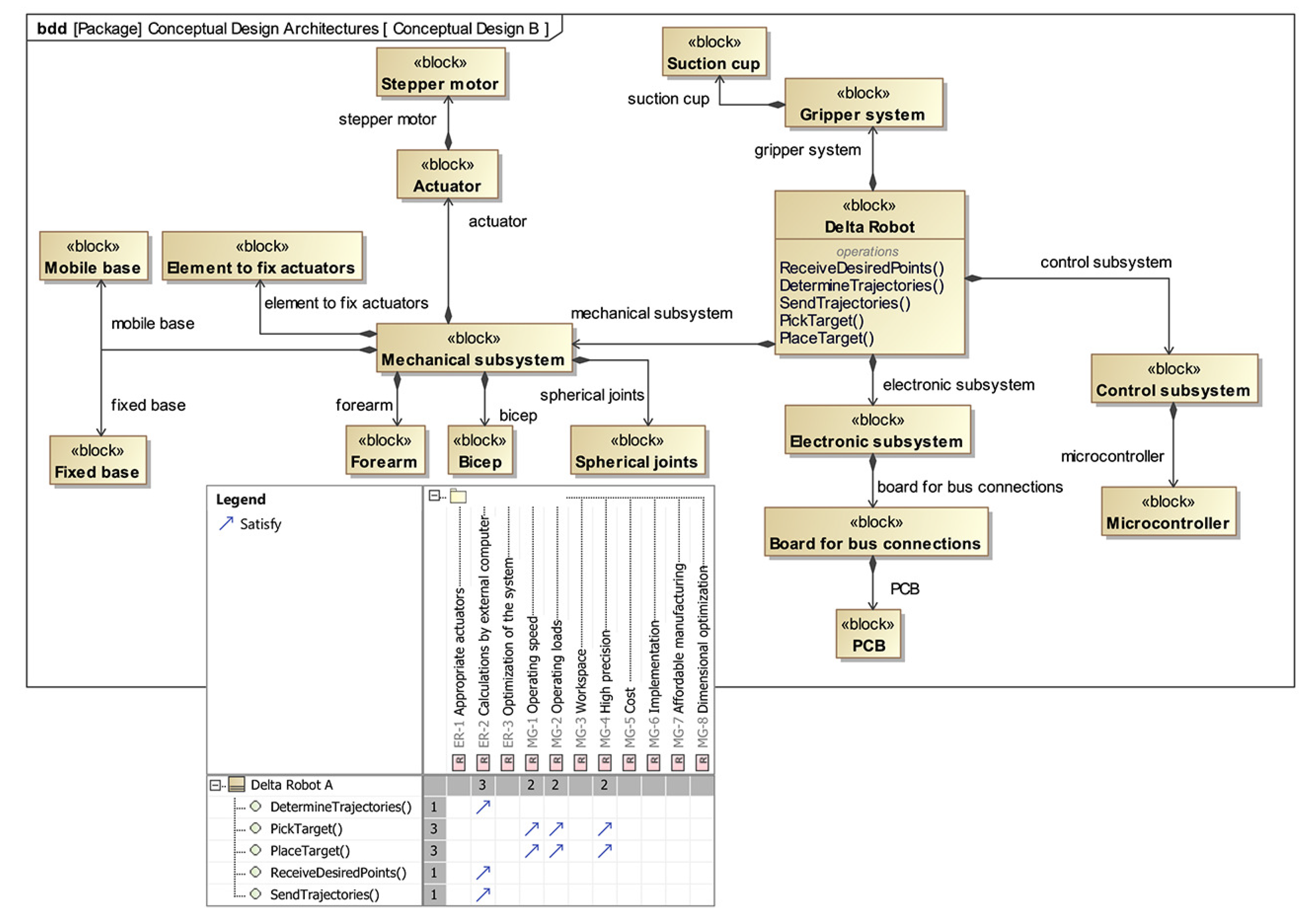
Conceptual design B with Choquet integral weights (bdd).

Figure 9.
Conceptual design C with Choquet integral weights (bdd).

Figure 10.
Choquetintegral simulation within the modeling tool.

Figure 11.
Conceptual design B (bdd), satisfying the matrix between the requirements and high-level operations.
Figure 11.
Conceptual design B (bdd), satisfying the matrix between the requirements and high-level operations.

Figure 12.
SysML internal block diagrams for the logical architecture of the system (ibd).

Figure 13.
SysML parametric diagram for pick and place task (par) and simulation performed in a specialized software.
Figure 13.
SysML parametric diagram for pick and place task (par) and simulation performed in a specialized software.

Figure 14.
Tools integration for the optimization and testing process.

Figure 15.
Final optimized architecture reaching different points within the desired workspace.

Figure 16.
Optimal kinematic architecture for the Delta robot.

Figure 17.
Final optimized architecture. (a) CAD rendering, (b) physical prototype, (c) mounting at the conveyor belt.
Figure 17.
Final optimized architecture. (a) CAD rendering, (b) physical prototype, (c) mounting at the conveyor belt.


Table 1.
Comparison of the conceptual architectures.
| Conceptual Design | Mechanical Subsystem | Gripper Subsystem | Electronic Subsystem | Control Subsystem |
|---|---|---|---|---|
| A | Servomotor | 3D Printed | Protoboard | Microprocessor |
| B | Stepper motor | Suction cup | PCB | Microcontroller |
| C | Servomotor | Suction cup | Protoboard | Microcontroller |
Table 2.
Choquet integral evaluation.
| Conceptual Design | Dependability | Cost | Complexity | Choquet Integral |
|---|---|---|---|---|
| A | 0.17 | 0.25 | 0.30 | 0.2185 |
| B | 0.33 | 0.45 | 0.55 | 0.4090 |
| C | 0.17 | 0.60 | 0.61 | 0.3660 |
Table 3.
Component selection for the Delta robot.
| Subsystem | Component | Number of Parts |
|---|---|---|
| Mobile base | 1 | |
| Fixed base | 1 | |
| Element to fix actuator | 3 | |
| Bicep | 3 | |
| Forearm | 6 | |
| Mechanical | SA3T/K (M3) spherical bearing | 12 |
| Stepper motor Nema 17 | 3 | |
| Hex nut (1/8" diameter) | +15 | |
| wire, 22 gauge | 50 [cm] | |
| M3 screw (1/8" diam. × 5/8" long) | +9 | |
| M3 screw (1/8" diam. × 1.5" long) | +6 | |
| Electronic | PCB | 1 |
| Controller | Microcontroller (Arduino uno) | 1 |
| Gripper | Suction cup | 1 |
Table 4.
Results of the genetic algorithm.
| Simulation | Number of Points N | Number of Generations | Number of Individuals | Vector of Solution x | Workspace Maximization [m] |
|---|---|---|---|---|---|
| 8 | 100 | 50 | 50 | [0.2, 0.1, 0.1122, 0.31] | 0.0029 |
| 20 | 100 | 50 | 10 | [0.2011, 0.0983, 0.1277, 0.2095] | 0.0029 |
| 22 | 50 | 50 | 10 | [0.2, 0.07, 0.19, 0.2738] | 0.0029 |
| 25 | 50 | 100 | 50 | [0.2986, 0.0964, 0.1003, 0.3082] | 0.0029 |
| 27 | 100 | 100 | 50 | [0.2, 0.07, 0.19, 0.2] | 0.0029 |
Publisher’s Note: MDPI stays neutral with regard to jurisdictional claims in published maps and institutional affiliations. |
© 2022 by the authors. Licensee MDPI, Basel, Switzerland. This article is an open access article distributed under the terms and conditions of the Creative Commons Attribution (CC BY) license (https://creativecommons.org/licenses/by/4.0/).
Share and Cite
MDPI and ACS Style
Portillo-Vélez, R.d.J.; Burgos-Castro, I.A.; Vásquez-Santacruz, J.A.; Marín-Urías, L.F. Integrated Conceptual Mechatronic Design of a Delta Robot. Machines 2022, 10, 186. https://doi.org/10.3390/machines10030186
AMA Style
Portillo-Vélez RdJ, Burgos-Castro IA, Vásquez-Santacruz JA, Marín-Urías LF. Integrated Conceptual Mechatronic Design of a Delta Robot. Machines. 2022; 10(3):186. https://doi.org/10.3390/machines10030186
Chicago/Turabian StylePortillo-Vélez, Rogelio de Jesús, Iván Andrés Burgos-Castro, José Alejandro Vásquez-Santacruz, and Luis Felipe Marín-Urías. 2022. "Integrated Conceptual Mechatronic Design of a Delta Robot" Machines 10, no. 3: 186. https://doi.org/10.3390/machines10030186
Note that from the first issue of 2016, this journal uses article numbers instead of page numbers. See further details here.