Possible Applications of Additive Manufacturing Technologies in Shipbuilding: A Review


Department of Marine Maintenance, Faculty of Marine Engineering, Gdynia Maritime University, Morska Street 81-87, 81-225 Gdynia, Poland
*
Author to whom correspondence should be addressed.
Machines 2020, 8(4), 84; https://doi.org/10.3390/machines8040084
Submission received: 9 November 2020
/
Revised: 2 December 2020
/
Accepted: 9 December 2020
/
Published: 12 December 2020
(This article belongs to the Section Advanced Manufacturing)
Abstract
:3D printing conquers new branches of production due to becoming a more reliable and professional method of manufacturing. The benefits of additive manufacturing such as part optimization, weight reduction, and ease of prototyping were factors accelerating the popularity of 3D printing. Additive manufacturing has found its niches, inter alia, in automotive, aerospace and dentistry. Although further research in those branches is still required, in some specific applications, additive manufacturing (AM) can be beneficial. It has been proven that additively manufactured parts have the potential to out perform the conventionally manufactured parts due to their mechanical properties; however, they must be designed for specific 3D printing technology, taking into account its limitations. The maritime industry has a long-standing tradition and is based on old, reliable techniques; therefore it implements new solutions very carefully. Besides, shipbuilding has to face very high classification requirements that force the use of technologies that guarantee repeatability and high quality. This paper provides information about current R&D works in the field of implementing AM in shipbuilding, possible benefits, opportunities and threats of implementation.
1. Introduction
Additive manufacturing has gained great popularity over the last decade due to media interest in 3D printers. The main factor of this situation was the popularization of small and inexpensive 3D printers, designed for home use, producing objects from thermoplastic materials. Such devices have experienced the fastest development as a result of high demand, and for many they are the only association with additive manufacturing.
However, the origins of 3D printing date back much earlier than the last decade. The first patents for devices producing objects additively began to appear in the 1980s and the first commercial device using stereolithography technology was released in 1987 [1]. However, until the turn of the first and the second decades of the 21st century, these were niche technologies, very expensive and limited to only a small group of specialized applications. The popularization of fused deposition modeling 3D printers through the RepRap project [2] have been a driving force for the development of the entire 3D printing industry. It aroused interest in these techniques in many sectors of the economy and contributed to the discovery of new applications of additive manufacturing (AM).
In addition to thermoplastic based 3D printing, there are many other methods, including photosensitive resins curing, sand or composite powders bonding, powdered polymers and metals sintering or wire metal arc welding. Each of these technologies is characterized by different properties of the final product, need of providing special condition during manufacturing, production time, need of support structures or complexity of post-processing. These may result in the specific method not being applicable or financially justified in some cases. Due to the above mentioned, AM should not be considered as an alternative for every manufacturing method and it is not suitable for all cases. Compared to traditional manufacturing methods, 3D printing has a number of advantages but also has limitations that do not exist in conventional techniques. As most AM techniques are based on layer-by-layer manufacturing, defects such as poor layers adhesion, voids, porosity or shifted layers can occur. It may be caused by a controller glitch, machine fault, mistake in G-code or improper placement of the item on the manufacturing bed. Production defects can also occur, in some materials, due to temperature gradients, speed of printing or heat influence. Some of these defects can be difficult to notice but simultaneously they can lower the item properties drastically. These flaws can be a huge obstacle in implementing AM parts in safety related applications, where reliability is crucial. Repeatability problems mostly concern fused deposition modeling (FDM) printing, and the risk can be minimized by choosing more advanced materials or technology. However, it can increase the production cost significantly. This is why choosing the right material and 3D printing technology for the specific application is important, so the price, quality and strength of the component meet the design assumptions.
Industrial grade machines, especially based on powder bed fusion, are very expensive, both in purchase and operation, but they are characterized by very good parameters and print quality, which makes them reliable. They can provide a good return of investment, yet it strongly depends on the benefits, that 3D printing can contribute to each specific case. All parts designed for 3D printing should be customized for the process and use the potential of the manufacturing technology. For example, it has been proven that WAAM parts can outperform conventionally manufactured parts [3] in terms of mechanical properties. Combining this fact with the ability to optimize geometry that only AM can achieve, it can lead to a significant reduction in weight and waste material, while maintaining component strength.
In many industries, AM methods are used on a daily basis for prototyping, conceptual models, low-volume production [4], production of single, customized parts [5], assemblies simplification, mass reduction of parts [6], personalized items such as dental implants [7] or special tools [8]. A good example of using the AM potential is a BMW case. They developed a personalized thumb protector for employees who have to press large amounts of rubber plugs into the car body during production. The thumb protector can prevent pain and health issues. Every protector was personalized for each employee’s thumb shape, which was 3D scanned previously. Additive manufacturing enabled creation of items with personalized shapes in one production series. It would be difficult to obtain with conventional techniques.
Professional applications of 3D printers can be found in many sectors, including aerospace [9], automotive [8,10,11], medical [7], architectural [12] and jewelry [13]. Recently, development work on the use of 3D printing in construction has been ongoing [14]. Researches and trials are also being carried out in gastronomy, the clothing industry, sport equipment industry and in electronics.
Shipbuilding has gradually joined this group, through commitment to research and attempts to use parts made by AM. These activities bring together maritime market leaders from all over the world, which proves the great hope placed in 3D printing.
2. AM Technologies
3D printing is mostly divided according to used material, which indirectly determines the type of technology used for its processing. Some materials can be processed in multiple techniques, but different forms of raw material may be needed, for example, a wire for FDM and powder for Selective Laser Sintering (SLS). Technology and materials should be chosen based on required strength, physical properties, financial assumptions and purpose of the product. The selected process can differ significantly from the others due to cost, printing time, post-processing time and repeatability.
Most of the processes require post-processing, which may include removing support structures, sanding, polishing, painting, infiltration, heat treatment, chemical treatment or cleaning. It can be very time consuming and may have the biggest impact on the final cost of the product.
A common limitation for most of the AM methods is the size limit of the part. It is a big obstacle in shipbuilding since most of the marine parts used tend to be large and heavy. The source of the problem is the AM process itself. In most of the technologies the part is created by applying material, layer by layer, simultaneously fusing them. This results in an introduction of a significant amount of heat into the workpiece. In professional 3D printers, the processing chamber is heated but the fusing temperature is much higher. Because applying the subsequent layers is relatively slow, it causes a big temperature gradient across the manufactured part which results in significant shrinkage. This shrinkage may lead to dimensional inaccuracies, warping, displacement of the model during printing and cracks. It can be controlled in cases of small parts but is an issue in long and tall parts. This effect is present in FDM, stereolithography (SLA), digital light processing (DLP), liquid-crystal display (LCD), SLS and metal powder bed fusion (M-PBF) technologies.
The other problem affecting item size is printing head movement. In AM processing the printing head performs a movement, or the item is moved relative to the printing head in some cases, covering the cross-sectional area of the item, usually hundreds of times during the process. In order to achieve reasonable times for manufacturing the movement must be fast, especially when the best print quality layer height is desired to be as low as possible. Usually the print head is heavy, which is connected with high inertia and leads to vibration increase. Vibration can affect the quality of the print. Furthermore, providing too big a printing area creates difficulties with maintaining rigidity and proper geometry of printer frame, which can also affect the printing quality.
In order to provide high quality and reasonable printing times, it is necessary to limit the processing chamber volume and therefore item size.
2.1. Fused Deposition Modelling
The first and the most widespread group is thermoplastic 3D printing known as Fused Deposition Meodelling (FDM) or Fused Filament Fabrication (FFF). The material is fed in the form of a wire to the print head, in which material is brought to a plastic state by heating block and then pressed through a nozzle with an appropriately selected diameter. The print head extrudes the material on the work surface, according to the cross-sectional geometry of the manufactured workpiece. Movement is repeated layer by layer until a complete object is obtained. There are many materials that can be used with this technology, such as: polylactic acid (PLA), acrylonitrile butadiene styrene (ABS), high impact polystyrene (HIPS), thermoplastic polyurethane (TPU), nylon, polyether ether ketone (PEEK), polyethylene terephthalate (PET), polyethylene terephthalate glycol (PET-G) and composites in the matrix of some of the listed materials with reinforcements made of glass fibers, carbon fibers, wood, metals or ceramics.
Markforged has introduced composite 3D printing technology in two different technologies. The first is the use of a composite filament with a nylon matrix and discontinuous carbon fibers as reinforcement. The manufacturer declares an increase in bending strength in relation to pure nylon by 60% [15]. The second technology consists of introducing continuous reinforcements between the layers of thermoplastic material during the printing process. After completing the application of the declared number of layers of the base filament, an additional nozzle applies a layer of the reinforcing component, also in the form of a wire, according to the pattern declared in the CAD model. The reinforcement material can be Kevlar, glass fiber, carbon fiber or high strength high temperature glass fiber, shown in Figure 1.
In the case of a composite with carbon fiber, the manufacturer declares a 10-fold increase in bending strength compared to pure nylon, and according to tests carried out by it, greater strength than aluminum 6061-T6. The data is based on the manufacturer’s static bend tests in accordance with ASTM D790. Samples containing no reinforcement did not break. The results of the manufacturer’s tests are shown in Figure 2.
This technique is characterized by a relatively low printing resolution in comparison to other solutions, due to the way of distributing the building material. The accuracy in the XY axes is limited by the size of the printing nozzle, usually 0.4 mm. The resolution in the Z axis is connected with displacement of the print head or the working table along the axis, depending on the solution. The biggest reasonable displacement is usually 0.1 mm, above this value surface quality and layer adhesion will be poor. This method is characterized by a visible layering of the manufactured object and a clear anisotropy of mechanical properties along the Z axis.
2.2. Photopolimerization
Another group of devices is based on the photopolymerization phenomenon. These devices are equipped with a reservoir which is filled with photosensitive resin. The resin is cured by light, layer by layer. Main methods of curing are laser beam curing (stereolithography), DLP projector light curing or LCD generated light curing.
A typical SLA device consists of a movable work platform, a resin tank and a laser located under its bottom with a system of mirrors and lenses. The platform moves along the Z axis and the printed object is rotated upside down. In the initial phase, the platform is immersed in the resin tank and the distance between the working surface and the bottom of the tank is a set layer height, usually from 0.025 to 0.1 mm.
The DLP method is similar to SLA, it differs only by the light source—in stereolithography it is a laser, in DLP it is a DLP projector. The advantage of DLP is the ability to expose the entire surface of the layer at the same time, which significantly reduces the printing time. However, due to the high printing speed, there is a significant thermal shrinkage of the printed objects, which can lead to dimensional deviations, deformation or even cracking of the object. This phenomenon should be taken into account when designing.
The LCD technique is analogous to DLP, differing in the light source used—an LCD matrix is used instead of a projector. The LCD technique is characterized by a longer life of the light source, higher printing speed and lower quality of prints.
There is also multi jet printing/poly jet method, where the photosensitive resin is sprayed through a multi-nozzle battery and then cured with UV light. The process is repeated, layer by layer, until the complete item is finished.
2.3. Powder Technologies
Powder methods include polymer fabrication (selective laser sintering) and metal powders fabrication (direct metal laser sintering, electron beam melting or direct energy deposition). Although all the mentioned powder technologies use a concentrated energy beam to solidify a powdered material, they differ from each other significantly, especially between manufacturing of polymers manufacturing of metals. In all powder bed fusion technologies, except binder jetting, a thin layer of material is spread on the worktable surface and then selectively sintered or melted by concentrated energy beam (electrons or laser).
2.4. Multi Jet Fusion
Multi Jet Fusion technology, developed by the HP concern, resembles the inkjet printing technology used by them for decades. Cartridges with bonding and separating factors are used for printing. The bonding agent is applied to the cross-sectional surface of the printed object. Its task is to increase the absorption of heat emitted by the heat source. The release agent is sprayed around the edge of the printed object. Its task is to reflect thermal radiation, thus the material around the outer walls of the object is not bonded and its separation is much easier. This significantly increases the final quality of the item.
2.5. Binder Jetting
The binder jetting technology uses metallic powders, sand or ceramics that are bonded with a liquid binder. It is a fast, inexpensive method, allowing for obtaining objects with good visual properties. Binder jetting is used, inter alia, in industry as a method of making casting molds. During printing, it does not require a vacuum or protective gas atmosphere inside the working chamber or increased temperature. After the printing cycle, it is necessary to post-process the item. The first step is to clean the model of powder residue. Particular care is required as the model has not been hardened yet. The next stage is hardening the model at temperatures from 200 to 260 °C. The last stage, which is not obligatory, but allows increasing the density of the objects and reducing the porosity, is sintering in the furnace along with infiltration, for example, using bronze. Models with a melting points above the temperature of 900–1400 °C, are being infiltrated with bronze, via special bus, thanks to the capillary phenomena. Models during sintering and infiltration are covered with graphite powder. The binder jetting method does not require the use of support structures.
2.6. Selective Laser Sintering
In SLS technology, a laser melts a layer with a thickness of 60 to 150 μm [17]. This technology allows making complex items quickly, with low anisotropy, good surface quality and mechanical properties. It also does not require support structures, because the overhangs in the subsequent print layers are supported by the compact powder below. A characteristic feature of the SLS method is high porosity, which is visible as a granular texture of the finished object. This is due to the sintering process itself and the shape of the material grains. This is both an advantage, because items are easy to dye, and a disadvantage, because in case of using parts manufactured by SLS method in a humid environment, it should be previously protected with paint or varnish. Porosity also causes a significant increase in the brittleness. This is visible in the comparison of strength tests results for printed samples and identical, solid material in Table 1.
SLS allows usage of materials such as polyamides (PA), polystyrenes (PS), thermoplastic elastomers (TPE) or polyaryletherketones (PAEK). They are reliable materials widely used in industrial applications.
2.7. Metal Powders Fusion
Metals used in metal powder bed fusion (MPBF) include, steel, aluminum alloys, brass, titanium alloys and copper alloys. AM of metal powders is very complex, due to many factors that can affect the process: melting temperature, heat influence, temperature gradient, scanning speed, chemical composition of alloy, use of shielding gases or layer thickness. Contrary to SLS, printing from metal powders requires the use of support structures, because of greater shrinkage of the printed layers due to big temperature gradients between temperature of molten material and ambient temperature in processing chamber. Lack of supports could cause deformation or cracking of the object. Support structures in M-PBF play the role of stabilizing overhangs or thin elements of the model, and also act as a heat sink, helping to dissipate heat introduced into the object during melting. Items made with M-PBF methods are characterized by very good mechanical properties, shown in Table 2, similar to those made traditionally, low anisotropy and surface roughness similar to castings—Ra 4–20 µm.
Advanced researches are being conducted in the field of metal powder AM and there is still need for further development.
2.8. Electron Beam Melting
Electron beam melting (EBM) is a method technologically similar to SLS or MPBF, with the difference that instead of a laser as a heat source, a focused beam of electrons is used. The electron beam comes from the electron gun. The tungsten electron gun emits electrons that are accelerated to half the speed of light. The device is equipped with a system of coils whose task is to align the electron beam, focus it in such a way as to obtain the desired spot and deflect it to scan the working field.
As the EBM technology does not use any moving parts to move the heat source and the heat flux density is very high, the printing speed is one of the highest among other 3D printing techniques. Printing takes place in a vacuum to avoid energy loss through the collision of electrons with air molecules. Thanks to this, the process achieves an energy efficiency of 95%, which makes it 5–10 times more energy-efficient than laser sintering. An additional advantage of using the vacuum is the possibility of using reactive materials such as titanium alloys, but the available materials are very limited—Ti grade 2, Ti6Al4V, Inconel 718, CoCrMo [20].
2.9. Wire Arc Additive Manufacturing
WAAM, wire arc additive manufacturing, uses MIG/MAG or TIG arc welding method, where the material is fed in the form of a wire and the welding process takes place in an atmosphere of protective gases. There is also a variant that uses a laser beam as a heat source. Successive layers of material are welded onto each other using a welding robot. It is possible to manufacture very large elements, the dimensions are limited by the working area of the robot and the possible movable mounting system of the object. There are many materials available for arc welding, such as steels, copper nickel or aluminum alloys, depending on the expected properties of the final product. This method has a potential to shorten production time, compared to traditional methods such as casting, forging or machining, especially in the case of single and large items. It also significantly reduces costs, because it does not require the preparation of molds, dies or machine retooling. WAAM allows for considerable material savings, because usage of material only consists of the final object volume plus a few percent of the allowances for final processing.
2.10. Researches in the Fields of Additive Laser Manufacturing
Kürnsteiner et al., performed research on the laser metal deposition (LMD) process in which a focused laser beam creates a melt pool in the component’s surface [21]. Material, which is metallic powder, is delivered via nozzle to the melting pool. As neighboring tracks and subsequent layers are deposited during the LMD process, already consolidated material experiences a cyclic reheating. This intrinsic heat treatment (IHT) can be used to trigger the precipitation reaction in precipitation hardening alloys. Kürnsteiner and his team tested maraging steels of different Al at % content, to identify an alloy composition that responds well to the IHT of the laser additive manufacturing (LAM) process to produce an in-process precipitation strengthened maraging steel. They used atom probe tomography (APT) to gain detailed information about the composition. This technology is very efficient in analyzing small clusters and precipitates. High energy synchrotron X-ray diffraction (HEXRD) was used to provide crystallographic information with high sensitivity. As a result of performed research they found the optimal Al concentration, which allows obtaining high density of NiAl precipitates created by IHT of the LAM process. Hardness was measured in the different layers of the sample, showing increase in hardness from 300 to 530 HV, associated with high density of mentioned precipitates.
Research on the Ti-64 manufactured with use of selective laser melting (SLM) method described by Barriobero-Vila et al. [22], concerns a microstructure in advanced geometries. In the additive laser manufacturing (ALM) as-built condition, this alloy usually presents brittle martensitic microstructures as well as anisotropy provoked by epitaxial grain growth across the solidified layers. Many researches are based on typical coupon or block shaped samples which differ significantly compared to complex geometries. As an example, they manufactured a rocket engine impeller. They observed that the microstructure formation and the amount of defects associated with the microstrain are linked to the local heat input during SLM. Compared to coupons built with equal SLM parameters, the component’s geometry and building direction have a relevant role on microstructure formation.
Grain refining of Ti-based alloys produced by ALM can be achieved, which proves research performed by Marco Simonelli et al. [23]. Research included works on decomposing martensite structures to α and β microstructure by adding solute, which can refine prior-β grains in Ti alloys. They considered many elements, including silicon, molybdenum, beryllium, chromium, boron, tungsten, iron and rare-earth elements. The result of the research proves the addition of Fe combined with post-processing heat treatment can decompose as-built microstructure of Ti-6Al-4V-3Fe to fully laminar α + β microstructure.
Ultrafine eutectic Ti-Fe alloys can gain strength above 2.5 GPa in room temperature and compressive ductility above 10% [24]. In these alloys, grain sizes commonly decrease with increasing growth velocity or cooling rate. This allows significant size-hardening effects and opens a gateway to materials design by rapid solidification techniques. The study presented by Gussone et al. [24] provides the first demonstration of the feasibility of producing eutectic and near-eutectic Ti-Fe alloys by LAM with ultrafine microstructures and mechanical strength as well as compressive ductility attractive for structural applications.
3. The Demand for 3D Printing in Shipbuilding
The marine industry is a specific area that generates huge demand for products and services from many other industries, such as carpentry; metallurgy; machinery and electromechanical industries; industrial automation; heating, ventilation air conditioning (HVAC); energy recovery systems; exhaust after treatment systems; corrosion protection systems; fire protection systems and petrochemicals. The supply demand forecast for years 2016–2025 is presented on the Figure 3.
Ships are equipped with thousands of devices and items, consisting of hundreds of parts. These devices are subject to failures and due to the specificity of the ship’s operation, are often subject to the requirements of classification societies for periodic replacement or regeneration. The operation of a ship usually involves travelling tens of thousands of kilometers to distant countries for commercial purposes. Due to the above factors, the maritime industry has very extensive supply chains, connecting many manufacturers, distributors, service providers and customers around the world. Figure 4 shows the number of marine supplies companies, in the 20 most important countries in the marine industry.
This requires constant coordination of teams, orders and ongoing projects as well as monitoring of the geopolitical or legal situation in the world. This is due to the fact that the service or product must be delivered where the ship currently is. In some parts of the world, there may be complications, longer delivery times, inability to provide a service or part of it, or a significant increase in the cost of such services.
The way to minimize the risks associated with the logistics of products and services is to implement the Industry 4.0 solutions into shipbuilding, whose general goal is to digitize and optimize processes using modern digital technologies [26]. Additive manufacturing is listed as one of the key technologies supporting the implementation of Industry 4.0 solutions in the marine industry. According to assumptions of this vision, AM should fulfill sustainability paradigms, known as LARG, which is an acronym for lean, agile, resilient and green [27]. In the lean area, the aim is to introduce large-scale production of small product series with a strong customer orientation and to maximize production while minimizing waste [28]. The results of the agile paradigm are to include customer-specific products and processes [29]. The implementation of resilient’s objectives is to result in production located geographically as close as possible to the customer, which will positively reduce the response time [30]. The adaptation of industry to green’s objectives includes technologies allowing the use of techniques for the re-use and recycling of urban waste [31]. It is worth noting that the goals set by LARG sustainability paradigms need fundamental change in global scale, requiring both consumers and suppliers to focus on implementing these solutions. This will involve a completely new model of order execution, business cooperation, raw material management, as well as changes in logistics and storage. Full implementation of the above assumptions is a long-term process worth pursuing, bearing in mind the gradual introduction of components. Growing interest in changing the supply chain with AM solutions is shown on Figure 5 by increased the number of related publications in recent years.
Relying heavily on traditional solutions, the maritime industry can react reluctantly to sustainability implementation attempts in the context of using additive manufacturing techniques. This is due to the fear of high investment costs associated with the implementation of 3D printing, as well as the need to train staff and adapt to the new business model, and thus to create new procedures, processes and solutions. Some companies, using traditional solutions, feel confident in the market, arguing their reluctance to change with good financial results and a well working business model [32]. The relatively short period of 3D printing usage in professional applications can also raise concerns, therefore AM may be perceived as immature technology. This impression may be enhanced by the fact that standards and classification guidelines for 3D printing are still under development and publications are gradually beginning to appear in this area. At the same time, it should be remembered that many companies have been in the 3D printing industry for several decades, and over the course of their operation they have developed their own standards and processes, thanks to which their solutions are characterized by repeatability and high quality of manufactured items.
In recent years the number of companies that have already applied or are interested in implementing AM in their production is increasing across many sectors, which is shown in Figure 6.
Furthermore, the awareness of AM has risen significantly, which is shown in Figure 7, due to EY report published in 2019.
Additive manufacturing methods can be used both for the manufacture of new parts used in the shipbuilding and for the repair and regeneration of wearing components. In the first case, the benefits of 3D printing can be related to material savings, the ability to optimize the shape of the object, the use of dispersed production and on-demand production, easy prototyping and the ability to adapt parts to the needs and expectations of the customer. Three-dimensional printing as a method of regeneration is not yet a technology developed enough to be widely used and pilot and experimental work is currently underway. The vision for the development of incremental methods in the context of machine parts regeneration includes repairing parts no longer manufactured or difficult to obtain without the need to make copies of them or repair components that are difficult to disassemble. Such repair can be carried out directly on the machine. This solution will also work during emergency part regeneration to allow for the continuation of short-term operation, for example, ad hoc repair of parts to reach the shipyard where the general repair will be carried out.
3.1. Wearing Components
There are many devices on board that are subject to wear as a result of working in unfavorable conditions—high temperature, corrosive environment, continuous operation—and therefore need to be repaired. Parts of these machines can often be remanufactured through technological treatments that restore their initial properties. This reduces repair costs and often repair times, as you do not have to wait for new spare parts to be delivered, only those items that can be repaired if:
- – the operational potential has not been exhausted,
- – repair costs are significantly lower than the price of the new item.
In the case of marine engine components, the first condition may be met if the damage to the component is caused by tribological, erosive or corrosive factors [34]. Due to working conditions, such damage most often affects components operating at high temperatures, under high pressure, interacting with other parts or working in corrosive environments, for example, seawater or exhaust gases. These include, for example, cylinder liners, pistons, cylinder heads, plain bearings, gears, shaft journals, pump components, manifolds and valves. Choosing the right technology, some of these elements can be regenerated using AM methods. Repair of worn items depends on several factors, such as the cost-effectiveness of the repair, its feasibility, the place of its execution, the service life of the reconditioned component or the time of repair. The service life of the remanufactured components can match the new parts, and it is assumed that a properly reconditioned element can go through this process up to six times [35]. The range and capabilities of repair are estimated based on measurements and visual evaluation of the element, such as the search for cracks, measurements of dimension and shape tolerances, roughness and based on the data such as the date of manufacturing, worked hours and the number of repairs made. After such verification, you can decide whether the item is repairable, what its scope is to be, and what the tools and materials should be used.
3.2. Use of 3D Printing on Board
Three-dimensional printing in general does not require either very advanced infrastructure or large spaces; however, adapting a production facility onshore to perform additive production is easier than using these technologies on board. The difficulties are due to limited space, adverse effects of temperature fluctuations and vibrations on board. In addition, an investment in an expensive 3D printer for occasional use on board may not be economically justified. Considering implementation of a 3D printer onboard, most reasonable seems to be using one or two devices, preferable working in FDM technology, which is the cheapest and most resistant to adverse environmental conditions and at the same time the most versatile.
Green Ship of the Future, funded by the Danish Maritime Fund, which works with companies such as Alfa Laval, DNV GL, Man Energy Solutions and Maersk, is conducting extensive research into the possibilities of using 3D printing in ongoing repairs. Between 2016 and 2018, they attempted implementing 3D printers on board [36]. They used nine FDM printers on six ships and two rigs. The crews were to use 3D printing for ongoing repairs and for making tools and fixtures useful for daily use and repairs. The exact results of the tests are not available, but due to published data it can be estimated that the crews did not exploit the full potential of the provided equipment. This may have been due to the quality and limitations of the entrusted equipment, the lack of training, the lack of design capabilities or skills or the failure to provide adequate 3D models. The use of an advanced AM device onboard may be hindered by its dimensions, price, service difficulties and working conditions. To achieve high quality and good properties, the machine must be properly calibrated and positioned. On board the ship there is practically permanent rocking and vibration, the temperature changes dramatically depending on the season, time of day or geographic region. All these factors can negatively affect print quality. The operation of advanced 3D printers also requires proper training, a range of specialized materials and proper conditions to store them and to be assured that the 3D printer can operate without hindrances. Of course, these factors can be avoided using the right materials and installations on board, but this significantly increases the implementation costs. When considering this kind of solution, it is necessary to take into account the criticality of the manufactured parts and the cost associated with the technical facilities for 3D printing. Even for strategic items on board, it may be cheaper to have them stored in the event of a breakdown. At the moment 3D printing on board seems rational only by the FDM method, in which fiber-reinforced composites can be used. The mechanical properties of these composites are very high, which allows the construction to bear heavy loads; moreover, the device and materials are relatively cheap. This allows parts such as tips, clamps, tools, handles, washers, enclosures, covers, gaskets, fixtures and other simple non-crucial components to be produced, as well as emergency parts that need to last as far as the nearest port for replacement by a high-quality part. This is the most likely role of 3D printing onboard in the current state of naval technology and solutions. In specific cases, more advanced methods may be used, but prior preparation of the infrastructure and crew is necessary, this requires testing of what events would justify the cost and effort of implementing 3D printing on board so that the benefits outweigh them.
3.3. Using 3D Printing on Land
In the maritime industry, downtime is the costliest. Vessels, regardless of type, are designed for transport and make a profit when in motion. Any stop, whether due to loading, unloading or failure, generates huge costs without making a profit. A one day stop of a ship with a payload of 5000 TEU, twenty-foot equivalent unit, brings a loss estimated at around EUR 40,000 [37]. Of course, the loss depends on the type and size of the ship, the size of the crew and other economic factors. That is why it is so important to carry out repairs as soon as possible and to limit the ship’s time in port to a minimum. In the case of planned repairs such as class renewal processes, it is already known what the scope of the work will be and when they will take place. You can prepare for this by pre-ordering the parts and optimizing the repair process.
In the event of a breakdown, crews often have to deal with the problem at the nearest port using resources, specialists and parts available at the site. Parts, tools and specialists can usually be transported to the place where the ship is located, but this may extend downtime for further days. This generates costs not only resulting from delivering parts, often very large and heavy, over long distances, but also resulting from the ship’s stay in port. The answer to this problem may be dispersed production based on AM techniques. This would allow manufacturers and spare parts suppliers to deliver their products within hours instead of days or weeks. This vision includes equipping manufacturing facilities located in ports’ surroundings with suitable 3D printers capable of printing the required part based on digital data provided by the manufacturer. This is particularly important for old and specialized ships, where many parts are not standard and must be made to order. In this case, the waiting time can reach a few weeks. Most suitable for machine parts production in most cases are M-PBF technologies, like MPF or EBM. They are characterized by the highest print quality, ability to produce quality metal parts and are fast and precise.
Almost every part used in machine design and shipbuilding can be produced in several ways using different manufacturing techniques. Their selection is based on the constructor’s assumptions, but they are indirectly determined by the manufacturer’s machine park, the valuables of the technology, the size of the series of the manufactured object and the estimated production time. Taking into account all factors, as a result of analysis, the optimal manufacturing methods should be selected to ensure minimum costs, maximum possible quality of the manufactured component and a sufficiently short production time. Depending on the result of the analysis, the same detail can be done using different tools. Taking a propeller as an example, it can be made classically, in the process of casting into a mold prepared by hand imprinting the stencil in the molding mass. In this case, the stencil could be prepared by 3D printing, which can positively affect the reproduction of the shape, the speed of its preparation or the amount of material used and thus the mass. Another method may be casting in a form prepared on a 3D printer. This form is prepared by alternating layers of sand and binder by the device, which are then cured [38]. This method allows you to obtain very high-quality casting molds in a short time. The propeller can also be made 100% in the 3D printing process, using WAAM technology which is automated wire arc welding. As you can see, the execution of the same detail can take place using different technologies, depending on the production volume, the expected quality, the complexity of the detail and the resources held.
3D printing can either only partially participate in the manufacturing process or be the only technology used. This depends on the balance of profits and costs that accompany the choice of the technology. The greatest profit should be seen in applications where 3D printing can replace elements that have so far consisted of multiple parts with a single element. This reduces installation costs, joints and sealing elements as well as saving time spent on their selections or installation time. It is also important to increase reliability, as each joint of the two components is a potential weak spot that can be damaged.
Significant savings can be achieved for parts normally produced by machining from metal blocks, especially expensive materials. Production by AM saves a significant part of the material lost in subtractive machining and reduces the production time of a single component, which also translates into energy consumption by the machine. These factors lead to measurable benefits of replacing traditional manufacturing with incremental methods, but cost analysis is required for each application.
4. Analysis of the Possibility of Using Spare Parts Made by Additive Manufacturing Methods in the Shipbuilding
This section presents case studies of the AM technologies used in naval equipment and research on 3D printing development in the maritime industry. The projects described in this chapter are carried out by leading companies, organizations, consortia and research centers operating in the maritime sector. These examples were used to analyze the possibility of using spare parts made by AM methods in shipbuilding.
4.1. RAMLAB and WAAM—Propeller
RAMLAB is a Dutch company that aims to develop AM technologies that can be implemented in shipbuilding. RAMLAB was established in cooperation with the Port of Rotterdam, Innovation Quarter—an organization supporting the development of innovation in the region—and RDM Makerspace—an organization dedicated to sharing space, technology and substantive support for young start-ups in the new technology industry. Damen, Shell, Autodesk, Lincoln Electric, The Linde Group, MAN Energy Solutions and the universities of Delft and Twente are also partners of RAMLAB.
The main technology developed by RAMLAB is WAAM, an acronym for wire arc additive manufacturing, which is based on layer by layer welding using MIG/MAG welding robots (Figure 8). The material is fed in the form of wire, which is justified economically, because in this form a variety of materials are available, and their price is much lower than metallic powders. The development of WAAM technology is multilevel—from research on used materials, through real-time monitoring of welding parameters using sensors and cameras, to the optimization of the design process for this method.
RAMLAB has so far made two objects that have been successfully implemented in the industry. The first is the so-called WAAMpeller (Figure 9), which is a propeller made entirely with WAAM technology. The propeller was manufactured in cooperation and on behalf of DAMEN shipyard, which used it to drive a Stan Tug 1606. The entire manufacturing process was supervised by Bureau Veritas, which also issued certifications for the propeller [39]. The material used was an aluminum, nickel and bronze alloy, and the print consisted of 298 layers. Figure 9 shows one of the prototypes.
The second product is a crane hook manufactured for Huisman Equipment. The work was carried out in cooperation with the classification societies DNV GL, Bureau Veritas and ABS in order to systematize 3D printing processes for certification and compliance with standards and to verify properties of the produced prototype [40]. The manufactured hook had four arms with a span of 1 m and its weight was 1 t. An improvement of this design compared to typical hooks was modeling of empty spaces in its interior, which with traditional techniques would be very difficult to obtain (Figure 10). The use of a hollow shell in the structure allowed reducing of the weight of the hook significantly while maintaining similar lifting values.
Research results published by Kim et al. [3] comparing ASTM B 150 (NAB) aluminum-nickel bronze (NAB) samples produced by casting and additive manufacturing using WAAM technology, prove that the mechanical properties are better for 3D printing. The samples produced by AM had 50% higher tensile strength, 20% higher yield point and 60% greater elongation. Moreover, the samples produced with the WAAM method showed a 28% increase in hardness and higher abrasion resistance.
A significant anisotropy of 3D printed elements was also noted—samples tested along the print direction achieved better results. When designing elements manufactured using WAAM technology, the influence of anisotropy must be taken into account.
4.2. Green Ship of the Future—Implementation of 3D Printing on Ships
In 2016, the cooperation of Green Ship of the Future was established with leading maritime companies: Alfa Laval, Clorius Controls, Copenhagen Business School, Create it Real, DNV GL, Force Technology, J. Lauritzen, Maersk Drilling, Maersk Tankers, MAN Energy Solutions, OSK ShipTech, PJ Diesel Engineering and Thürmer Tools [36]. The cooperation aimed to undertake development work on the use of 3D printers working onboard the ship, scaling additive technologies towards the production of large ship structures, 4D printing, that is, from materials that remember the shape, as well as the possibility of repair and reconstruction of parts using 3D printing.
The attempt to implement 3D printers on ships was made by equipping six ships and three rigs with desktop 3D printers working in FDM technology. Crews have been asked to test new technology and to print parts that are not critical for the ship’s operation and safety and which are often being damaged or are difficult to order. Items that have been printed during this test are for example, powder extinguisher end nozzle, lathe lever knobs, DIN rail fuse mounts or handrail brackets for the engine control room (Figure 11). Considering the quantity and complexity of the components produced, it can be seen that the crews were skeptical about the new solution, which may have been due to a lack of knowledge of device capabilities, lack of operation skills of the device, sufficient 3D models for printing were not provided, lack of CAD software or skills to create their own models.
During the test, the possibility of printing spare parts from external manufacturers on board the ship was considered. Due to the need to protect the intellectual property of the company, no manufacturer will agree to provide full models of its products. The solution to this problem could be to make e-models available as a streaming service, analogous to popular services with legal online music, where music can be listened to, however, it is not possible to save and process a file with its content. The model would be shared directly to 3D printer using encryption and security protocols, which would prevent unauthorized access to files.
4.3. Oak Ridge National Laboratory—Submarine Hull
In 2017, the U.S. Navy, in collaboration with Oak Ridge National Laboratory, developed a composite submarine hull (Figure 12) made of carbon fiber-containing material using the big area additive manufacturing (BAAM) additive technique. The built hull is a SEAL delivery vehicle (SDV) designed to transport U.S. Navy SEALs and their equipment during maneuvers. The length of the hull is over 9 m.
The production of this type of boat by conventional methods generates costs of 600–800 thousand USD, and the time it takes to produce one piece is between three and five months [41]. The use of AM allows you to limit the production time to a few weeks and the cost reduction can be up to 90%.
4.4. Wärtsilä—Mounting for Cylinder Liners
The Finnish marine engine manufacturer is seriously interested in implementing additive methods in its operations. Development is underway to implement parts manufactured in direct metal laser sintering (DMLS) 3D printing technology in marine engine components. Wärtsilä works on AM technologies in their R&D centers in Italy and Finland. In the long term, Wärtsilä plans to develop dispersed production, which involves the use of many 3D printers located in Wärtsila branches around the world, producing the necessary parts according to demand. This is to reduce storage costs due to storage space reduction and the need to provide adequate warehouse conditions as well as investment costs associated with the production of large series of items that are usually stored for years. Dispersed production can also reduce time and delivery costs, as the necessary item can be produced locally without waiting for transport from a warehouse located on the other side of the world.
In 2019, Wärtsilä successfully introduced a 3D printed device to carry the assembly of a cylinder liner with piston and connecting rod, which is to replace the tool currently in use. Until now, a tool made of steel in the machining process (Figure 13) has been used to carry cylinder liners.
Such a manufacturing process is very time consuming and requires a suitable machine park. Since the component is relatively large, not every manufacturer is able to produce it, therefore Wärtsilä has a limited number of subcontractors producing these tools. This limitation creates the need to send these devices to Wärtsila’s branches around the world and to ships undergoing repairs. The final cost of operation of the instrument is very high due to the amount of material lost during machining, long machining time and transport costs.
It was decided by the team of innovation engineers led by Juho Raukola, an AM expert at Wärtsilä, to reduce these expenses, in collaboration with Markforged, using their innovative FDM printing technology supported by continuous carbon fiber reinforcement. They developed a multi-element solution to optimize the shape for 3D printing and to exploit the full potential of reinforcement. In this way, the weight of the instrument was reduced by 75% while maintaining a load capacity of 960 kg and reaching a safety factor of 4 [42]. Figure 14 shows the strength tests of the mounting.
4.5. AM JIP—Additive Manufacturing Joint Industry Programme
The program is being implemented by MPA (Maritime and Port Authority of Singapore), AM cluster (NAMIC—National Additive Manufacturing Innovation Cluster) and SSA (Singapore Shipping Association) in cooperation with, among others, Wärtsilä or DNV GL and many other companies affiliated with SSA. The aim of this cooperation is to conduct research into the possibilities of implementing 3D printing in shipbuilding. The first phase of the project, which was completed in October 2019, focused on the analysis of 600,000 spare parts used by the companies involved in the project. The information was collected in the form of surveys, interviews and repair reports. After analyzing all the collected data, 100 items were selected, which were divided into three categories [43] (Table 3).
It should be taken into account that the information has been collected from different shipowners about ships of miscellaneous purpose, equipment and age. Many components may have been repeated, but also, they may have been parts of different manufacturers or adapted to diverse operating conditions. The data collected by the main research team from the AM JIP partners was intended to help assess the feasibility and commercial viability of potential parts that could be 3D printed. However, it is not possible to clearly classify these parts without a precise definition of the area of application and a thorough verification of the technical details. Therefore, the categorization of the parts was carried out with the assumptions and limitations described below:
3D printing without class certification—it is assumed that the parts listed in this category are used in components that are not crucial to ship safety and are therefore not class certified. However, some of these parts can be used in components that are subject to class certification.
3D printing with class certification—it is assumed that the parts listed in this category are used in components that are sensitive safety areas of the ship and are therefore subject to class certification, such as main engine, auxiliary engine, et cetera.
Impossible to print 3D—the parts listed in this section were selected on assessment of the benefits of incremental methods, as reported by the project research team. Non-printable 3D may be interpreted as commercially or technically inappropriate for various reasons, such as shape, weight or material type.
Ivaldi, one of the companies cooperating with JIP, through nearly three years of research has developed a digitization method that makes AM economically viable for the marine industry. They have created a platform which allows them to produce almost any part for their customers, relying on sent technical documentation, which leads to reducing waiting times and costs. Wilhelmsen Ship Services (WSS), which is one of Ivaldi’s investors, uses its own facility located in the Port of Singapore to 3D print parts on demand and supplies them to various WSS customers. Below are case studies of AM parts implementation performed by Ivaldi, the figures are presented in Table 4 [43].
Cast iron handwheel:
Traditional handwheels often damage valve stems which leads to costly equipment replacement and delays. AM technologies have been used to replace cast-iron handwheels with spares made of polyamide. Polymer handwheels prevent damage to valve stems caused by traditional handwheels.
Guide bar:
At the customer’s request, Ivaldi produced a stainless-steel guide. Traditional purchasing processes lasted up to 12 weeks and had an average cost of 20,000 USD. Because the guides are not mass produced, the waiting time is long, and the cost of unit production is very high. Production and delivery using the Ivaldi platform cost 1250 USD and were completed in less than 72 h. This is about 38% of the cost savings for the end user.
Bolt cover:
During visits to ships carried out by the Ivaldi team, a problem was noticed with the polymer bolt caps used to protect the threads of the holding bolts. The covers used to crack and slid off the screws, which required frequent replacement. The team encountered this problem on many ships. Responding to demand, Ivaldi engineers redesigned the bolt covers, adding an internal thread to them to help hold them in place. This allowed crew members to reduce the cost of replacing additional bolt guards.
Scupper plugs:
3D printing also allows the creation of multi-component parts, such as scupper plugs. Ivaldi provides end-users with access to individual components that are not available from manufacturers who sell the entire complete assembly. Crew members can choose to replace individual components instead of the entire scupper plug, which significantly reduces the total cost of replacement.
4.6. Own 3D Printed Elements
As an element of research, parts that can easily be 3D printed and are applicable in shipbuilding were proposed. These parts can be made in any AM technology. In this case, FDM technology was chosen due to availability and low cost of production. The manufactured components are not designed to bear loads, so typical thermoplastic materials used in FDM printing will work very well in these applications. The selected material is PET-G, which has good mechanical properties, resistance to humidity, temperature and ultraviolet light.
4.6.1. Name Plate
Due to the high complexity of marine systems, clear identification and marking of pipelines, electrical installations or equipment such as pumps, tanks, radiators and valves is very important. This is crucial for the safety of the ship’s operation and allows the crew to quickly and undoubtedly identify what the element is and to which system it belongs. For this purpose name plates are used, which are placed on pipelines, cabinets, tanks, valves or enclosures. Typically, these plates are engraved at the shipowner’s request and placed in designated locations. During the operation of the vessel, modifications are often carried out and new name plates with different content are needed or existing ones need to be repeated elsewhere for easier identification. In order to improve this process and minimize the lead time of name plates, it was designed in a CAD environment and optimized for 3D printing. During prototyping work, several versions of the plates were tested—with concave painted inscriptions, convex single-color inscriptions and convex contrasting color inscriptions. As a result of their comparison, the signs with convex inscriptions in contrasting color were found to be the most visible (Figure 16). An additional element designed together with the plate is a pipe mounting which can be easily adjusted, before printing, to dimensions of any pipeline (Figure 17).
Three dimensional printing in this application allowed a significant reduction in the cost of purchasing name plates and mountings. It is estimated that the AM mounting cost is 80% lower than buying the end product, excluding shipping costs. The cost of producing one piece of the mounting has been estimated according to the following formula:
where is the total cost of producing part (USD), is printing time (h), is 3D printer power consumption (kW), is cost of electricity per 1 kilowatt-hour (USD/kWh), is cost of material per 1 kg (USD/kg), is length of used material (m), is wire diameter (m2), is material density (kg/m3), is the cost of purchasing a 3D printer (USD), is 3D printer life span in years, is number of printer operating days per year and is 3D printer operating time in one working day (h).
The cost of producing one piece of mounting has been calculated based on the following data:
4.6.2. Thread Protective Cap
Due to the long lifecycle of marine equipment and related repairs, it is essential that the equipment is maintained in a condition that can be dismantled and then reassembled. It is important to protect the fasteners from damage. In the case of elements like bolts, threaded studs or rods, damage can be caused by impact, dirt or corrosion. To prevent this, an inside-threaded protective cap was designed (Figure 18) that, thanks to the use of an internal thread, sticks to the secured element which prevents against accidental fall. In addition, the cap can be equipped with an O-ring to protect against moisture. Design of this part was inspired by an Ivaldi solution, described in Section 4.5.
5. Profits from 3D Printing Implementation in Shipbuilding
Additive manufacturing is classified among artificial intelligence or the internet of things as one of the pillars of the modern industrial revolution, known as Industry 4.0. The emergence of new technologies, digitization, widespread automation, the development of artificial intelligence and process improvements create new opportunities for industry, trade and logistics. Some of these changes are already visible, but in many aspects the scope of changes is difficult to estimate. AM technologies have many advantages that can reduce supply chains, reduce material costs and delivery times. In addition, they allow for freely optimizing parts and to make details which are very difficult or impossible to achieve by other techniques. AM technologies are estimated to generate approximately 100 billion USD in revenue in the Countries of the Association of Southeast Asian Nations (ASEAN), which will amount to approximately 1.5 to 2% of their GDP [44]. Three dimensional printing has great potential in the maritime industry, with significant benefits in the short term, but the current level of implementation is very low [45]. According to AM professionals, creating AM business clusters can be an opportunity for mutual instilling of ideas between companies, accelerating innovation [43].
Compared to conventional manufacturing techniques, 3D printing has a very high potential that can bring real financial benefits, as well as in terms of weight reduction or optimization of the shape of objects while maintaining utility properties. This is due to the high versatility and adaptability of 3D printing, so that in some cases 3D printing can successfully replace the entire machine park used to produce the component. Table 5 represents the potential benefits for maritime industry.
The following are the potential benefits of implementing AM techniques in the maritime sector [43]. The information collected relates mainly to the Asian market, due to the current greatest interest in 3D printing in this area, which results in the largest amount of data available. However, they are largely universal for other markets as well, including the European one.
5.1. More Efficient Procurement
AM techniques can help reduce the cost of supplying parts. On-demand production and local production can reduce inventory and thus costs. This reduces supply chain complexity and brings production closer to the customer in order to better adapt and ensure quality [46]. By 2022, it is estimated that 85% of spare parts suppliers will implement 3D printing into their business [47].
5.2. Reduce the Cost and Time of Parts Delivery
Three dimensional printing can simplify and shorten the supply chain. AM technologies significantly reduce lead time, making the market more responsive. The current naval fleet spends approximately 13 billion USD per year on spare parts, and 50% of ships older than 15 years suffer from limited availability of spare parts (Clarksons Marine Fleet) [43]. For small series production, AM offers shorter lead times than traditional production methods. Significant time savings can be achieved by creating mesh-like structures that are highly durable and at the same time smaller in weight and volume than solid structures. The U.S. Navy successfully printed the hull of a small submarine in less than a month and under 60,000 USD. Construction of such a hull by conventional techniques costs about 600,000 USD and takes about 3 months [48]. Using 3D printing, Ford managed to develop multiple iterations of the prototype in just four days at a cost of only 3000 USD [11].
5.3. Improving Manufacturing Efficiency
Since most AM methods are based on layer-by-layer fabrication with minimal use of raw material for part production, waste can be significantly reduced and material costs reduced compared to traditional production methods [49]. The ratio of the volume of raw material used in traditional production to the volume of the finished product may be up to 20:1 [50]. Incremental techniques can reduce material allowances to just a few percent, which are only necessary due to subsequent finishing or the need to create support structures.
5.4. Weight Reduction and Simplification of Structures
Three dimensional printing provides the ability to reduce weight or volume with greater freedom to optimize the design [46,49]. By optimizing the topology and working with network structures, you can reduce the weight and cost of parts [51]. Naval Group and Centrale Nantes have successfully made a hollow stainless-steel propeller using WAAM technology. The reason being improving the efficiency of the propeller and reducing the noise and vibration emitted compared to conventional ones [52]. The use of multiple materials or different structures in the construction of a single element may reduce its total weight and cost while retaining the highest possible properties [53,54].
5.5. Easier Part Optimization
Thanks to AM, we are able to overcome the constraints of other methods and perform elements that so far have been used as an assembly, in the form of a single part or objects that cannot be done conventionally. This creates completely new design opportunities at a small additional cost [46]. Some spare parts can also be redesigned to improve functionality. The ease and speed of prototyping using AM methods allows the part to be tested long before its production runs and allows for many iterations of the prototype, thanks to which many errors can be eliminated and advanced optimization can be carried out [51]. Three dimensional printing also creates unique alloys and composite materials to increase mechanical strength, modify the coefficient of thermal expansion and control the material properties [55]. In 2019, Wärtsilä, in cooperation with DNV GL, developed a nozzle for the inert gas installation for oil tankers in M-PBF—metal powder bed fusion technology, as shown in Figure 19. Thanks to 3D printing, much better regulation and spray performance was achieved [56].
5.6. Digital Model Database
The possibility offered by 3D printing is so-called dispersed manufacturing, in an on-demand production system which can enable a digital model base. This database would include models of spare parts, together with information of materials, mechanical properties, manufacturing technologies. The geometrical properties and parameters of each part are entered into the database via CAD design, creating a digital “twin” of the part. Each part entered into the database is cataloged and saved. The digital database is one of the important steps in view of the upcoming digitization process within Industry 4.0 [57].
By integrating with CAD/CAM software, as well as with a view to the development of the internet of things and artificial intelligence, it is possible to significantly reduce the supply chain and latency, and eventually produce parts and deliver them to a port that the ship will visit next, just before a breakdown or planned overhaul. It is a vision that assumes development of the internet of things to the level that the entire engine room is equipped with sensors live-monitoring the condition of the devices. Software using artificial intelligence on the basis of the collected data, information about the ship’s stock and supplies as well as its location, next destination and available infrastructure in the port, would make decisions about ordering and delivering parts within the optimal time and financial framework.
5.7. Environmental Impact
Mehrpouya et al. [58] distinguishes three main aspects in which 3D printing affects the environment:
- Resource utilization: In the context of 3D printing, mainly electricity and construction material are consumed. Compared to conventional techniques, material consumption is significantly lower, but the energy consumption per part may be higher due to low production throughput, especially in high-temperature 3D printing processes. Please note that for traditional production, the energy consumption per part will vary depending on the scale of production. When comparing single production to 3D printing, AM tends to be more energy efficient.
- Waste management: waste treatment generates significant amounts of waste, which can be reduced by up to 90% by using 3D printing [59]. This is possible thanks to the use of only the volume of material that the final product has, plus the amount of allowances for support structures and finishing.
- Contamination control: compared to traditional manufacturing techniques, 3D printing needs much less potentially harmful chemicals, such as casting anti-stick compounds, lubricants used in forging processes or coolant used in machining. Some 3D printing processes use small amounts of organic solvents for postprocessing.
6. Limits of Additive Manufacturing
Despite a number of advantages over conventional methods, 3D printing, as a collection of young technologies, is associated with risk and has some disadvantages. By being aware of these limitations and correctly selecting materials and methods for the application, manufacturing defects can be effectively avoided.
6.1. Scale of Production
The benefits of using 3D printing, considering their current performance, are inversely proportional to the production volume [60], therefore AM techniques are not cost-effective methods of mass production now. This situation may change with the development of 3D printers, which are likely to allow even faster, more energy-efficient and more repeatable production.
6.2. Repeatability of Production
Additive manufacturing is a dynamically developing but still young method of production. There are large discrepancies in the parameters of machines and materials from different manufacturers and operating in different 3D printing technologies. Each manufacturer uses different processes, materials, principles of printer operation, pre-processing and post-processing. This set of variables creates the possibility of errors during production, and the variety of methods makes it difficult to verify them. In addition, 3D printers are sensitive to interference, for example, in the power grid, sudden changes of temperature, humidity, vibration or even ambient light intensity when using photopolymers. They can cause printing errors such as poor layer connection, incorrect layer arrangement, layer thickness faults, surface imperfections and pores and voids inside the model [58]. This is the reason why it is so important to implement monitoring of parameters in 3D printing to optimize the process and avoid any manufacturing flaws. Classification societies such as Bureau Veritas and DNV GL are conducting advanced work in the field of AM normalization, making classification procedures and creating a set of guidelines to help different manufacturers achieve the same repeatable results.
6.3. Financial Outlays
Investments in equipment necessary to start AM-based production is associated with significant cost—industrial 3D printers’ prices start at several hundreds of USD and end at hundreds of thousands of USD [61]. A popular way to minimize the costs of implementing and developing AM techniques is business cooperation between manufacturers and companies specializing in 3D printing, as well as establishing consortia, to split the cost of AM implementation. This allows significant reduction in investment costs and exchanging of experiences and involving specialists from many fields in the project.
6.4. Small Pool of Specialists
Because 3D printing has recently started to be seen by people who are not only passionate about these technologies and inventors, there is still a lack of people with education and expertise in AM in the market [62,63]. Many people, even with technical backgrounds, have the vision of 3D printing as a way to get a fully functional product straight from the 3D printer. People familiar with these manufacturing techniques are aware of the limitations and necessity of printed parts’ post-processing, which is often more laborious than printing itself. The technical and engineering skills required for successful implementation of 3D printing range from modern design processes and knowledge of new material processing to data management from testing and process monitoring. In order for 3D printing to revolutionize production in the maritime industry, a well-trained and capable staff will be required [63]. Efforts to train staff as additive technology professionals are undertaken by universities, research clusters and companies around the world, where the greatest activity can be seen in Singapore, Finland, the Netherlands and the USA.
6.5. Creation of Industrial Standards
To effectively implement AM into industry, you need a set of standards to ensure that companies and manufacturers have processes, materials and 3D printing technologies that are safe and reliable. The International Organization for Standardization (ISO) and ASTM International have jointly developed the Structure for the Development of 3D Printing norms [64]. There are currently no standards for 3D printing for the maritime industry [60,65]. To enable widespread use of AM, constant quality and reliability must be ensured [51].
6.6. Class Requirements and Certification
Regulatory standards and norms specific to the maritime industry should be developed to deal with typical marine difficulties. Without standards, maritime companies face difficulties in evaluating and accepting additively produced items. Their assessment can only be based on general ISO/ASTM standards, which do not define requirements for the maritime industry [66].This situation is not acceptable because it leaves room for interpretation, which may result in the use of parts that do not have proper certification. Classification societies such as DNV GL and Bureau Veritas are trying to fill this gap by working with research centers using the expertise of industry professionals. The establishment of classification standards and guidelines will allow for unambiguous verification of AM produced parts [51].
7. Discussion
The purpose of this article was to present and discuss 3D printing implementation attempts in shipbuilding and activities carried out for the development of AM. Based on collected data, the possibility of using 3D printing in shipbuilding analysis was performed and the vision of 3D printing development was proposed. These examples include varied application areas, materials, dimensions and levels of complexity. Many 3D printing techniques were presented, differing significantly in characteristics.
AM as industrial manufacturing techniques are very young compared to conventional methods, which often raises skepticism in decision-makers [32]. The desire to maintain the status quo and the reluctance to risk associated with changing a production system that has been in operation for years, often makes the implementation of 3D printing just a forward-looking vision. Reliability and high quality of the delivered products are particularly valuable for the maritime industry, which is understandable from the perspective of safety at sea and the financial risks of possible accidents. However, large companies’ interest in AM, mentioned earlier in this article, indicates the perceived potential and gives hope for the dynamic development of 3D printing in the shipbuilding industry in the upcoming years. In addition, the involvement of classification societies in the development of 3D printing in the maritime industry demonstrates the desire to standardize AM and to enable the easy and safe manufacturing of parts by these methods.
Certain methods will never be used as manufacturing techniques for strategic components, for example, FDM method, due to the print quality, materials used and mechanical properties of the parts. However, they can successfully replace some parts produced by traditional methods with measurable benefits. One benefit is cost reduction and shortened manufacturing process.
Due to satisfying mechanical properties, low price of FDM devices and less sensitivity to environmental conditions such as dust, temperature, humidity, vibration or leveling, FDM printers can be successfully used onboard. For quick repairs of components such as hand wheels, handles, plugs, name plates and mounting brackets, FDM technologies seem to be ideal and equipping the engine room with affordable thermoplastic printing equipment can be a significant facilitation for crews performing simple repairs and improvements.
The methods that have the best chance of dynamic development in the maritime sector are DMLS, EBM, WAAM and binder jetting. These are methods that use metals, which distinguish them from others with much better mechanical properties of products, and this is crucial for applications in areas related to safety. In those methods the biggest companies see a future in production and the biggest benefits. Their disadvantage is the high price of printing material and devices.
For applications that do not require high surface quality, however, which focus on high print speed and low material price, the WAAM method can be a perfect solution. Components made by this method can be machined to the required dimensions and surface quality, but the detail straight after printing process is characterized by a very strong layering and irregularity of the surface.
Currently, 3D printed objects require more attention than conventionally manufactured counterparts. Even though competitive mechanical properties are possible to obtain, which was proven in researches, they often suffer from defects and rough surface finishes. Typical defects may be poor layer adhesion, warping, cracks, undesirable microstructure, shifted layers, porosity or voids. Moreover, in most cases it is necessary to cut the detail off the worktable and to remove support structure. These treatments are highly time consuming and are connected with risk of damaging the part.
The advantage of production using AM methods compared to conventional methods can be shape optimization, weight reduction, ease of object scaling, integration of several elements into one or use of better materials. A graphic interpretation of the benefits of AM methods in production is shown in Figure 20.
8. Conclusions
Additive manufacturing is still a new group of technologies and requires further research to gain the reliability of conventional manufacturing. It has potential to compete with traditional methods by parts’ properties and functionality but is still connected with high risk of manufacturing defects. Three dimensional printed parts require complex post-processing which generates additional expenses.
The use of 3D printing creates a number of possibilities for shipbuilding, such as reducing storage space, shortening the supply chain, reducing waiting times, reducing manufacturing costs, optimizing part design in a way that has not yet been possible and using materials not available for conventional techniques.
The factor that seems to be the most important in the context of shipbuilding is the dramatic reduction in waiting time for parts, because downtime is the biggest cost for shipowners. An equally important factor is the ability to disperse production and produce parts on demand. This would significantly reduce the costs of transportation, payment of customs duties and parts storage. High hopes are also placed in the optimization of parts, the replacement of subassemblies consisting of many elements into parts made as a monolith, which would be enabled by 3D printing. This would facilitate service works, shorten their duration and reduce the number of necessary elements. The risk of failure connected with the large number of connections, seals or assembly and production defects would be decreased.
It can also be used for on-board repairs, to reduce the downtime spent in the shipyard. With additive manufacturing, parts that are difficult to dismantle, like crankshafts or camshafts, could be repaired directly on the machine.
Presented examples mainly show simple parts that do not work in safety-critical systems. This is due to the initial phase of implementing 3D printing and reducing the consequences of possible errors. However, because of advanced research work carried out by numerous companies, organizations and universities, we can expect additively manufactured parts to be applied in critical areas, such as engine parts, propellers, safety installations and tools.
Author Contributions
Conceptualization, M.Z. and T.D.; methodology, M.Z.; software, M.Z.; validation, M.Z. and T.D.; formal analysis, T.D.; investigation, M.Z.; resources, M.Z.; data curation, M.Z.; writing—original draft preparation, M.Z.; writing—review and editing, M.Z. and T.D.; visualization, M.Z.; supervision, T.D.; project administration, T.D.; funding acquisition, T.D. All authors have read and agreed to the published version of the manuscript.
Funding
This research received no external funding.
Conflicts of Interest
The authors declare no conflict of interest.
Glossary
| ABS | acrylonitrile butadiene styrene thermoplastic polymer |
| AM | additive manufacturing |
| BAAM | big area additive manufacturing |
| CAD | computer aided design |
| DLP | digital light processing |
| DMLS | direct metal laser sintering |
| EBM | electron beam melting |
| FDM | fused deposition modeling |
| HVAC | heating, ventilation, air conditioning |
| M-PBF | metal powder bed fusion |
| PLA | polylactide |
| PBF | powder bed fusion |
| SLA | stereolithography |
| SLM | selective laser melting |
| WAAM | wire arc additive manufacturing |
References
- Gross, B.C.; Erkal, J.L.; Lockwood, S.Y.; Chen, C.; Spence, D.M. Evaluation of 3D Printing and Its Potential Impact on Biotechnology and the Chemical Sciences. Anal. Chem. 2014, 86, 3240–3253. [Google Scholar] [CrossRef] [PubMed]
- Jones, R.; Haufe, P.; Sells, E.; Iravani, P.; Olliver, V.; Palmer, C.; Bowyer, A. RepRap–The replicating rapid prototyper. Robotica 2011, 29, 177–191. [Google Scholar] [CrossRef] [Green Version]
- Kim, J.; Kim, J.; Pyo, C. Comparison of Mechanical Properties of Ni-Al-Bronze Alloy Fabricated through Wire Arc Additive Manufacturing with Ni-Al-Bronze Alloy Fabricated through Casting. Metals 2020, 10, 1164. [Google Scholar] [CrossRef]
- Godina, R.; Ribeiro, I.; Matos, F.; Ferreira, B.T.; Carvalho, H.; Peças, P. Impact Assessment of Additive Manufacturing on Sustainable Business Models in Industry 4.0 Context. Sustainability 2020, 12, 7066. [Google Scholar] [CrossRef]
- Grunewald, S.J. Koenigsegg Is Striving to Make the World’s Fastest Car with 3d Printing. Available online: https://3dprintingindustry.com/news/koenigsegg-striving-make-worlds-fastest-car-3d-printing-24773/ (accessed on 25 November 2020).
- Van Praet, K. Materialise Interviews Partner GE: “The Time for 3D Printing Is Now”. Available online: https://www.materialise.com/en/blog/materialise-interviews-partner-ge-time-for-3d-printing-now (accessed on 25 November 2020).
- Oliveira, T.T.; Reis, A.C. Fabrication of dental implants by the additive manufacturing method: A systematic review. J. Prosthet. Dent. 2019, 122, 270–274. [Google Scholar] [CrossRef]
- Lecklider, T. 3D Printing Drives Automotive Innovation. Available online: https://www.evaluationengineering.com/test-issues-techniques/technology/3d-printing/article/13014908/3d-printing-drives-automotive-innovation (accessed on 24 November 2020).
- Joshi, S.C.; Sheikh, A.A. 3D printing in aerospace and its long-term sustainability. Virtual Phys. Prototyp. 2015, 10, 175–185. [Google Scholar] [CrossRef]
- Stratasys. Five Ways 3D Printing Is Transforming the Automotive Industry; Stratasys: Rehovot, Israel, 2016; Available online: https://www.stratasys.com/explore/whitepaper/transforming-auto-industry (accessed on 24 November 2020).
- Giffi, A.; Gangula, B.; Illinda, P. 3D Opportunity for the Automotive Industry: Additive Manufacturing Hits the Road. Available online: https://www2.deloitte.com/us/en/insights/focus/ (accessed on 28 September 2020).
- Mathur, R. 3D Printing in Architecture. Int. J. Innov. Sci. Eng. Technol. 2016, 3. [Google Scholar]
- Yap, Y.L.; Yeong, W.Y. Additive manufacture of fashion and jewellery products: A mini review. Virtual Phys. Prototyp. 2014, 9, 195–201. [Google Scholar] [CrossRef]
- Mohan, M.K.; Rahul, A.V.; De Schutter, G.; Van Tittelboom, K. Extrusion-based concrete 3D printing from a material perspective: A state-of-the-art review. Cem. Concr. Compos. 2021, 115, 103855. [Google Scholar] [CrossRef]
- Markforged. Composite Materials Datasheet; Markforged: Watertown, MA, USA, 2019; Available online: http://static.markforged.com/downloads/composites-data-sheet.pdf (accessed on 28 September 2020).
- Markforged. Reinforced Materials; Markforged: Watertown, MA, USA, 2019. Available online: https://sfdesign.com.au/markforged-3d-printers/materials/. (accessed on 28 September 2020).
- Chlebus, E. Techniki Komputerowe CAx w Inżynierii Produkcji; Wydawnictwa Naukowo-Techniczne: Warsaw, Poland, 2000. [Google Scholar]
- Zieliński, D. Drukarki 3D: Technlogia SLS. Available online: https://drukarki3d.pl/technologie/technologia-sls/. (accessed on 28 September 2020).
- Zieliński, D. Drukarki 3D: Technologia DMLS. Available online: https://drukarki3d.pl/technologie/technologia-dmls/. (accessed on 28 September 2020).
- Gokuldoss, P.K.; Kolla, S.; Eckert, J. Additive Manufacturing Processes: Selective Laser Melting, Electron Beam Melting and Binder Jetting—Selection Guidelines. Materials 2017, 10, 672. [Google Scholar] [CrossRef] [Green Version]
- Kürnsteiner, P.; Wilms, M.B.; Weisheit, A.; Barriobero-Vila, P.; Gault, B.; Jägle, E.A.; Raabe, D. In-process Precipitation During Laser Additive Manufacturing Investigated by Atom Probe Tomography. Microsc. Microanal. 2017, 23, 694–695. [Google Scholar] [CrossRef] [Green Version]
- Barriobero-Vila, P.; Artzt, K.; Stark, A.; Schell, N.; Siggel, M.; Gussone, J.; Kleinert, J.; Kitsche, W.; Requena, G.; Haubrich, J. Mapping the geometry of Ti-6Al-4V: From martensite decomposition to localized spheroidization during selective laser melting. Scr. Mater. 2020, 182, 48–52. [Google Scholar] [CrossRef]
- Simonelli, M.; McCartney, D.G.; Barriobero-Vila, P.; Aboulkhair, N.T.; Tse, Y.Y.; Clare, A.; Hague, R. The Influence of Iron in Minimizing the Microstructural Anisotropy of Ti-6Al-4V Produced by Laser Powder-Bed Fusion. Metall. Mater. Trans. A 2020, 51, 2444–2459. [Google Scholar] [CrossRef] [Green Version]
- Gussone, J.; Bugelnig, K.; Barriobero-Vila, P.; Da Silva, J.; Hecht, U.; Dresbach, C.; Sket, F.; Cloetens, P.; Stark, A.; Schell, N.; et al. Ultrafine eutectic Ti-Fe-based alloys processed by additive manufacturing—A new candidate for high temperature applications. Appl. Mater. Today 2020, 20, 100767. [Google Scholar] [CrossRef]
- OECD. Merchant Shipbuilding Forecast 2016–2025; OECD, 2015. Available online: http://www.oecd.org/industry/ind/WP6-Workshop_Item_1.1.3_Brodda.pdf (accessed on 28 September 2020).
- Ramirez-Peña, M.; Abad Fraga, F.J.; Sánchez Sotano, A.J.; Batista, M. Shipbuilding 4.0 Index Approaching Supply Chain. Materials 2019, 12, 4129. [Google Scholar] [CrossRef] [PubMed] [Green Version]
- Carvalho, H.; Duarte, S.; Cruz Machado, V. Lean, agile, resilient and green: Divergencies and synergies. Int. J. Lean Six Sigma 2011, 2, 151–179. [Google Scholar] [CrossRef]
- Tuck, C.; Hague, R.; Burns, N. Rapid manufacturing: Impact on supply chain methodologies and practice. Int. J. Serv. Oper. Manag. 2007, 3, 1. [Google Scholar] [CrossRef] [Green Version]
- Christopher, M. The Agile Supply Chain. Ind. Mark. Manag. 2000, 29, 37–44. [Google Scholar] [CrossRef] [Green Version]
- Muthukumarasamy, K.; Balasubramanian, P.; Marathe, A.; Awwad, M. Additive Manufacturing–A Future Revolution in Supply Chain Sustainability and Disaster Management. In Proceedings of the International Conference on Industrial Engineering and Operations Management, Washington DC, USA, 27–29 September 2018. [Google Scholar]
- Nascimento, D.L.M.; Alencastro, V.; Quelhas, O.L.G.; Caiado, R.G.G.; Garza-Reyes, J.A.; Rocha-Lona, L.; Tortorella, G. Exploring Industry 4.0 technologies to enable circular economy practices in a manufacturing context: A business model proposal. J. Manuf. Technol. Manag. 2019, 30, 607–627. [Google Scholar] [CrossRef]
- Johannessen, L.K.K.; de Lange, L.C.H. Barriers for Adopting Additive Manufacturing in the Norwegian Oil and Gas Industry; University of Oslo: Oslo, Norway, 2019. [Google Scholar]
- EY. 3D Printing: Hype Or Game Changer? A Global EY Report 2019; EY, 2019. Available online: https://assets.ey.com/content/dam/ey-sites/ey-com/en_gl/topics/advisory/ey-3d-printing-game-changer.pdf (accessed on 27 November 2020).
- Bielawski, P.; Raunmiagi, Z. Naprawy Wybranych Elementów Okrętowego Silnika Spalinowego; Akademia Morska w Szczecinie: Szczecin, Poland, 2007. [Google Scholar]
- Haak, W. Reconditioning of Diesel Engine Components is it worth considering. In Seminarium WSM w Szczecinie; Archbishop Seminary: Szczecin, Poland, 2001; pp. 77–82. [Google Scholar]
- Green Ship of the Future 3D Print in the Maritime Industry from Concept to Implementation. Available online: https://greenship.org/wp-content/uploads/2019/02/3DPIII-rapport-1.pdf (accessed on 28 September 2020).
- Cardenal, J.P.; Araújo, H. Nieuchronny Podbój świata po Chińsku; Wydawnictwo Sonia Draga: Katowice, Poland, 2016; ISBN 978-83-7999-773-2. [Google Scholar]
- Voigt, R.; Manogharan, G. 3D Printed Sand Molds—An Opportunity for Investment Casters. Available online: https://www.researchgate.net/publication/328465511_3D_Printed_Sand_Molds-An_Opportunity_for_Investment_Casters (accessed on 28 September 2020).
- Frith, J. RAMLAB Gets Closer to the World’s First 3D Printed Props; Maritime Journal, 11 September 2017. Available online: https://www.maritimejournal.com/news101/power-and-propulsion/ramlab-gets-closer-to-worlds-first-3d-printed-props (accessed on 1 October 2020).
- METAL AM. Huisman and RAMLAB to Produce ‘World’s Heaviest’ Wire-Arc Additively Manufactured Crane Hook. Available online: https://www.metal-am.com/huisman-and-ramlab-to-produce-worlds-heaviest-wire-arc-additively-manufactured-crane-hook/ (accessed on 1 October 2020).
- Alexandrea, P. Navy Uses 3D Printing to Create Submarine Hull; 3D Natives, 26 July 2017. Available online: https://www.3dnatives.com/en/3d-printed-submarine260720174/ (accessed on 28 September 2020).
- Markforged. Wärtsilä Case Study. Available online: http://static.markforged.com/downloads/WartsilaCaseStudy.pdf. (accessed on 28 September 2020).
- NAMIC; MPA; SSA. Additive Manufacturing for Marine Parts a Market Feasibility Study with Singapore Perspective. Available online: https://www.mpa.gov.sg/web/wcm/connect/www/99a3720f-abfc-4b07-9c9b-467220c1000a/Additive+Manufacturing+Market+Feasibility+Study_Public+Version.pdf?MOD=AJPERES&id=1572312102868 (accessed on 28 September 2020).
- Eqiupment News. Asia Pacific Metal Working Equipment News: Additive Manufacturing To Generate US$100 Billion Economic Value in ASEAN by 2025. Available online: https://www.equipment-news.com/additive-manufacturing-to-generate-us100-billion-economic-value-in-asean-by-2025/ (accessed on 28 September 2020).
- Wong, K.Y. New programme to develop advanced manufacturing applications, services for maritime sector. Business Times, 17 April 2018. [Google Scholar]
- Holmström, J.; Gutowski, T. Additive Manufacturing in Operations and Supply Chain Management. J. Ind. Ecol. 2017, 21, 21–24. [Google Scholar]
- Geissbauer, R.; Lehr, J.; Wunderlin, J. The Future of spare parts is 3D: A look at the challenges and opportunities of 3D printing. PwC Strategy, 30 January 2017. [Google Scholar]
- National Interest. The Navy Can Now 3D-Print Submarines on the Fly for SEALs. Available online: https://nationalinterest.org/ (accessed on 28 September 2020).
- Tofail, A.S. Additive manufacturing scientific and technological challenegs, market uptake and opportunities. Mater. Today 2018, 21, 22–37. [Google Scholar] [CrossRef]
- Ford, S.; Despeisse, M. Additive manufacturing and sustainability: An exploratory study of theadvantages and challenges. J. Clean. Prod. 2016, 137, 1573–1587. [Google Scholar] [CrossRef]
- Thompson, M.K. Design for Additive Manufacturing: Trends, opportunities, considerations and constraints. CIRP Ann. - Manuf. Technol. 2016, 65, 737–760. [Google Scholar] [CrossRef]
- Naval Group: The World’s First Hollow Propeller Blade. 2019. Available online: https://www.naval-group.com/en/worlds-first-hollow-propeller-blade-638 (accessed on 28 September 2020).
- Attaran, M. The rise of 3-D printing: The advantages of 3-D printing over traditional manufacturing. Bus. Horiz. 2017, 60, 677–688. [Google Scholar] [CrossRef]
- Zagórski, K.; Dudek, P. Cost, resources, and energy efficiency of additive manufacturing. E3S Web Conf. 2017, 14, 1–9. [Google Scholar]
- Baumers, M. Informing additive manufacturing technology adoption: Total cost and the impact of capacity utilisation. Int. J. Prod. Res. 2017, 55, 6957–6970. [Google Scholar] [CrossRef] [Green Version]
- DNV·GL. Testing the Potential of Additive Manufacturing. Available online: https://www.dnvgl.com/expert-story/maritime-impact/testing-the-potential-of-additive-manufacturing.html. (accessed on 28 September 2020).
- Mandolla, C. Building a digital twin for additive manufacturing through the exploitation of block chain: A case analysis of the aircraft industry. Comput. Ind. 2019, 109, 134–152. [Google Scholar] [CrossRef]
- Mehrpouya, M.; Dehghanghadikolaei, A.; Fotovvati, B.; Vosooghnia, A.; Emamian, S.S.; Gisario, A. The Potential of Additive Manufacturing in the Smart Factory Industrial 4.0: A Review. Appl. Sci. 2019, 9, 3865. [Google Scholar] [CrossRef] [Green Version]
- Khajavi, S.H.; Partanen, J.; Holmström, J. Additive manufacturing in the spare parts supply chain. Comput. Ind. 2014, 65, 50–63. [Google Scholar] [CrossRef]
- Jing, L.; Myant, C.; Wu, B. The Current Landscape for Additive Manufacturing Research (2016 ICL AMN Report); Imperial College London: London, UK, 2016. [Google Scholar]
- Shah, J. Large-scale 3D printers for additive manufacturing: Design considerations and challenges. Int. J. Adv. Manuf. Technol. 2019, 104, 3679–3693. [Google Scholar] [CrossRef]
- Thomas-Seale, L. The barriers to the progression of additive manufacture: Perspectives from UK industry. Int. J. Prod. Econ. 2018, 198, 104–118. [Google Scholar] [CrossRef]
- Despeisse, M.; Minshall, T. Skills and Education for Additive Manufacturing: A Review of Emerging Issues; Centre for Technology Management, Institute for Manufacturing, University of Cambridge: Cambridge, UK, 2017. [Google Scholar]
- ASTM. ASTM and ISO Additive Manufacturing Committees Approve Joint Standards under Partner Standards Developing Organization Agreement; ASTM: West Conshohocken, PA, USA, 2013; Available online: https://www.astm.org/cms/drupal-7.51/newsroom/astm-and-iso-additive-manufacturing-committees-approve-joint-standards-under-partner. (accessed on 28 September 2020).
- Kostidi, E.; Nikitakos, N. Is It Time for the Maritime Industry to Embrace 3d Printed Spare Parts? University of the Aegean: Chios, Greece, 2017. [Google Scholar]
- Bangert, M. Additive Manufacturing Standards. Appl. Des. Troy 2017, 65, 33–34. [Google Scholar]
Figure 1.
Presentation of cross-sections of composite prints using various reinforcing materials, from the left: carbon fiber, glass fiber, high-strength high-temperature glass fiber and Kevlar [16].
Figure 1.
Presentation of cross-sections of composite prints using various reinforcing materials, from the left: carbon fiber, glass fiber, high-strength high-temperature glass fiber and Kevlar [16].

Figure 2.
Bending stress as a function of deformation. On the left, material not continuously reinforced; on the right, with the continuous reinforcement [16].
Figure 2.
Bending stress as a function of deformation. On the left, material not continuously reinforced; on the right, with the continuous reinforcement [16].

Figure 3.
Marine supply demand per trade [25].
Figure 3.
Marine supply demand per trade [25].

Figure 4.
Number of companies in top 20 countries [25].
Figure 4.
Number of companies in top 20 countries [25].

Figure 5.
Number of publications related to searched phrase: “Additive Manufacturing in shipbuilding”, by lens.org (26 November 2020).
Figure 5.
Number of publications related to searched phrase: “Additive Manufacturing in shipbuilding”, by lens.org (26 November 2020).

Figure 6.
Experience of additive manufacturing (AM) technologies per industry [33].
Figure 6.
Experience of additive manufacturing (AM) technologies per industry [33].

Figure 7.
Awareness about AM technologies [33].
Figure 7.
Awareness about AM technologies [33].

Figure 8.
Welding robot as the main element of wire arc additive manufacturing (WAAM) printing.

Figure 9.
WAAM prototype.

Figure 10.
Crane hook during the 3D printing process.

Figure 11.
Components made by onboard 3D printing [36].
Figure 11.
Components made by onboard 3D printing [36].

Figure 12.
Submarine hull made incremental techniques for the US Navy [41].
Figure 12.
Submarine hull made incremental techniques for the US Navy [41].

Figure 13.
Mounting previously used by Wärtsilä personnel [42].
Figure 13.
Mounting previously used by Wärtsilä personnel [42].

Figure 14.
Strength tests of the new mounting [42].
Figure 14.
Strength tests of the new mounting [42].

Figure 15.
The mounting after successful certification was put into operation in Wärtsila workshops [42].
Figure 15.
The mounting after successful certification was put into operation in Wärtsila workshops [42].

Figure 16.
Models of the designed name plate and the mounting. From the top: name plates, view from the back and front, the mounting and the assembly of all components.
Figure 16.
Models of the designed name plate and the mounting. From the top: name plates, view from the back and front, the mounting and the assembly of all components.

Figure 17.
Photos of the plate and mounting produced in fused deposition modeling (FDM) technology.

Figure 18.
From the left: a 1/4-section view and a full view of assembly showing the essence of the protective cap. Photo of an FDM-printed cap mounted on a bolt.
Figure 18.
From the left: a 1/4-section view and a full view of assembly showing the essence of the protective cap. Photo of an FDM-printed cap mounted on a bolt.

Figure 19.
Nozzle manufactured by Wärtsilä [56].
Figure 19.
Nozzle manufactured by Wärtsilä [56].

Figure 20.
Graphic representation of the benefits of using 3D printing in shipbuilding.


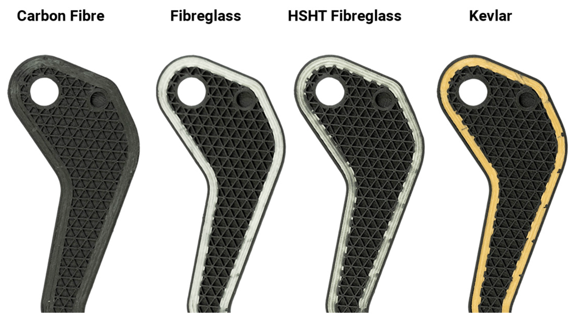
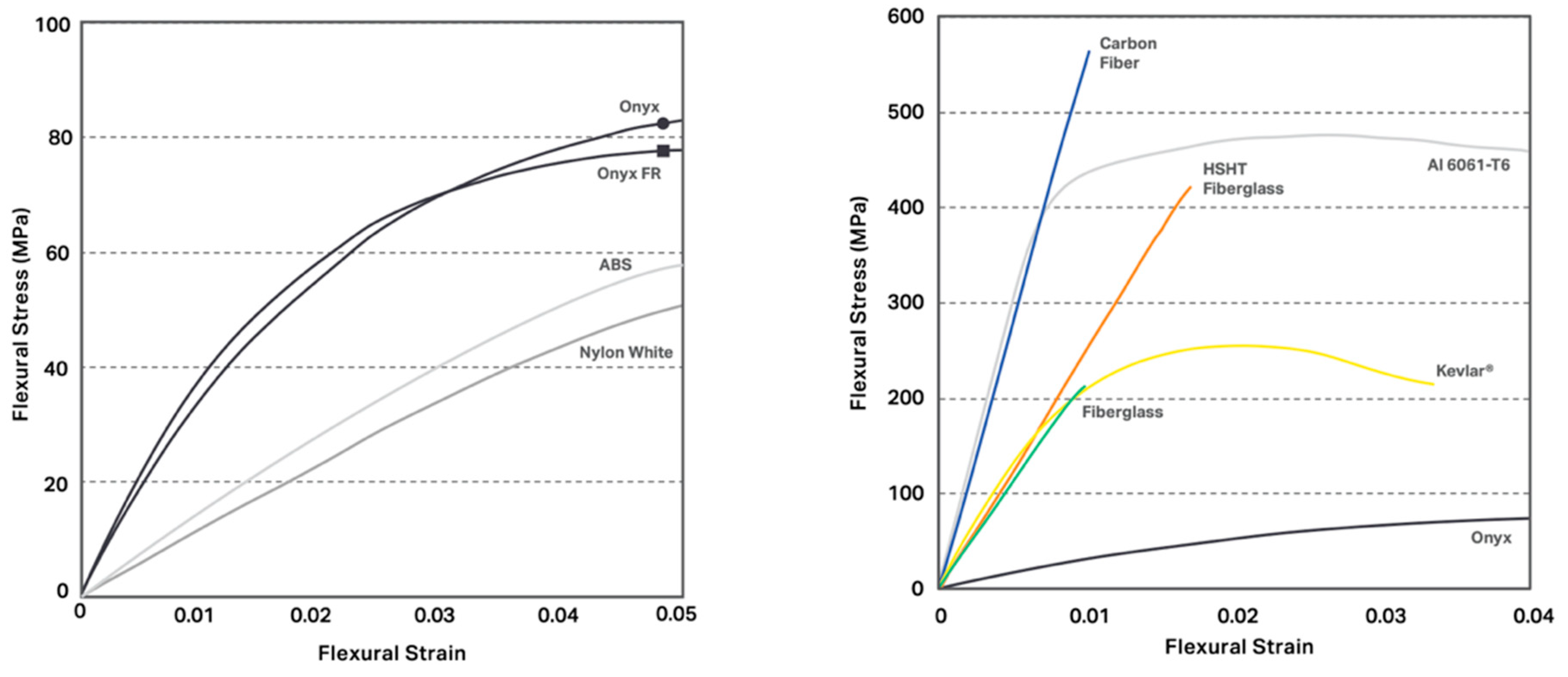
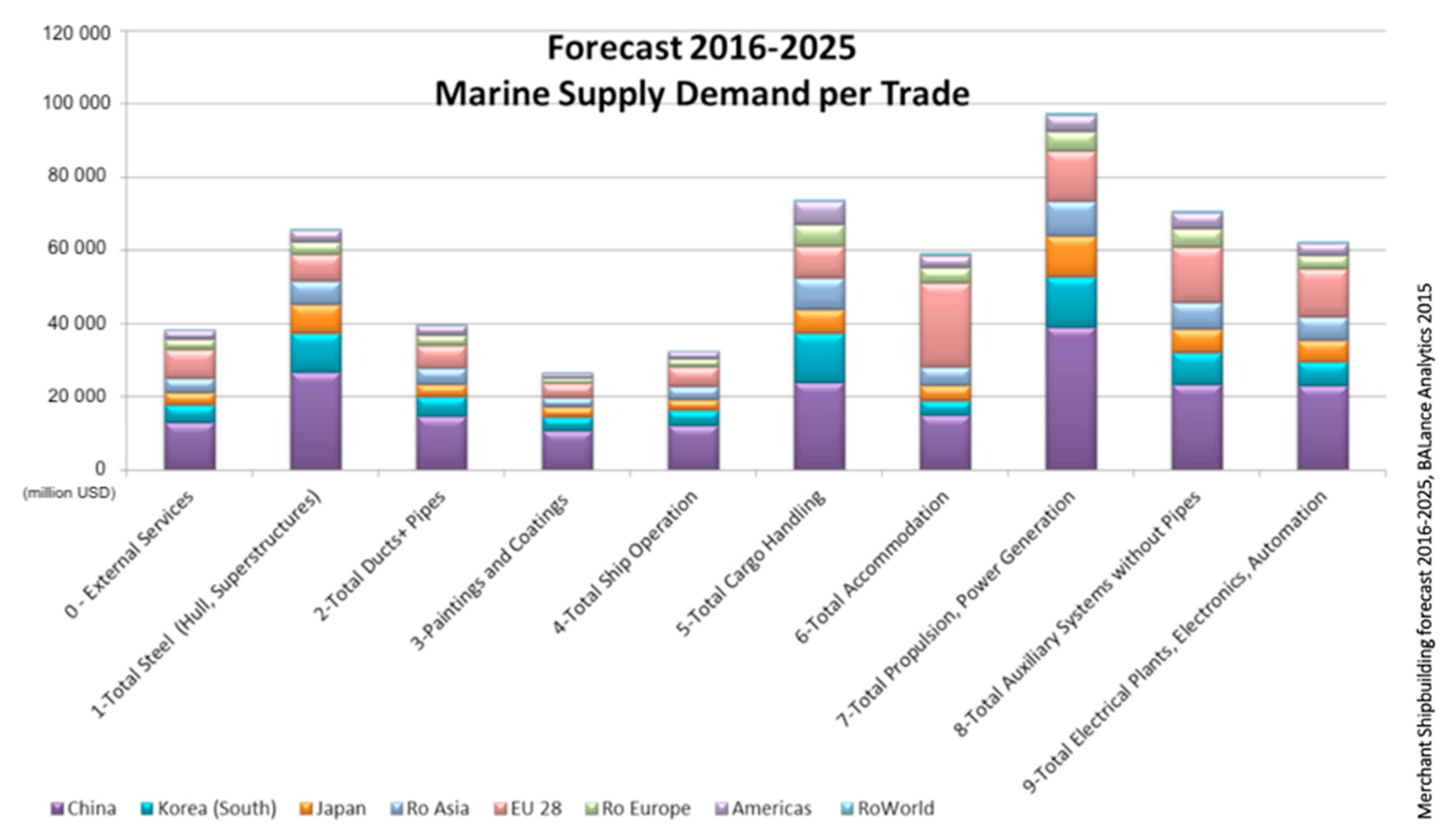
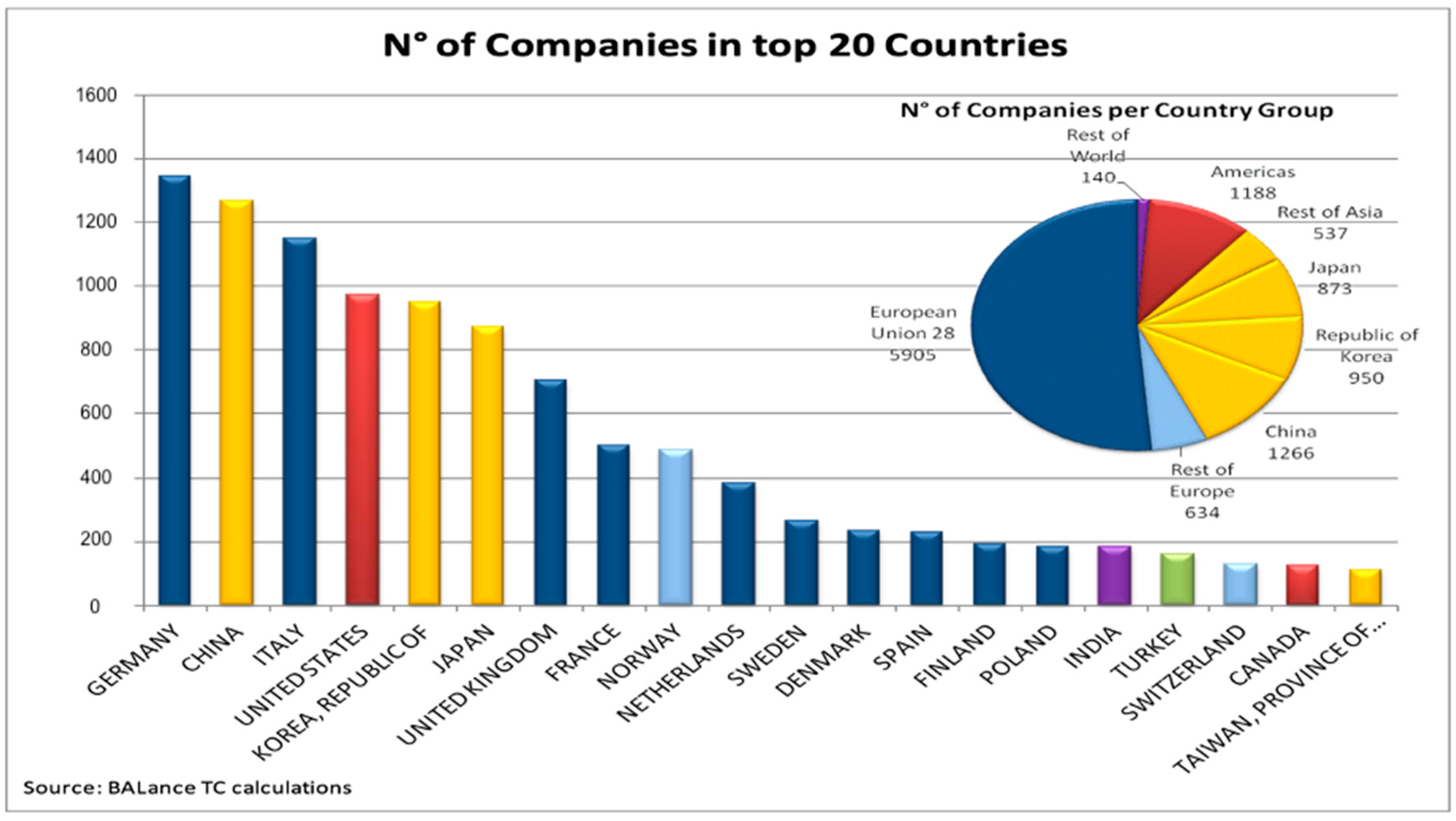
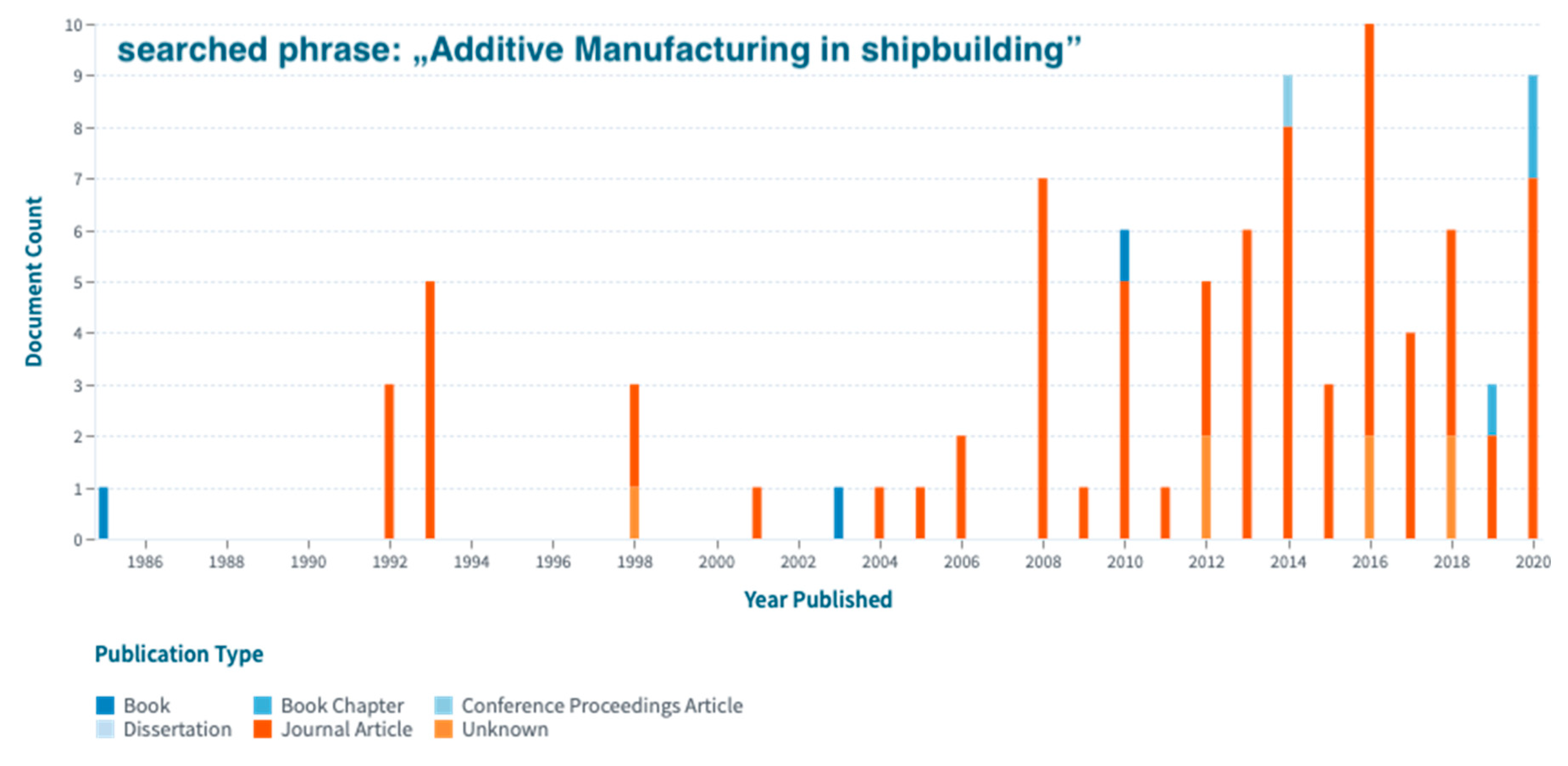
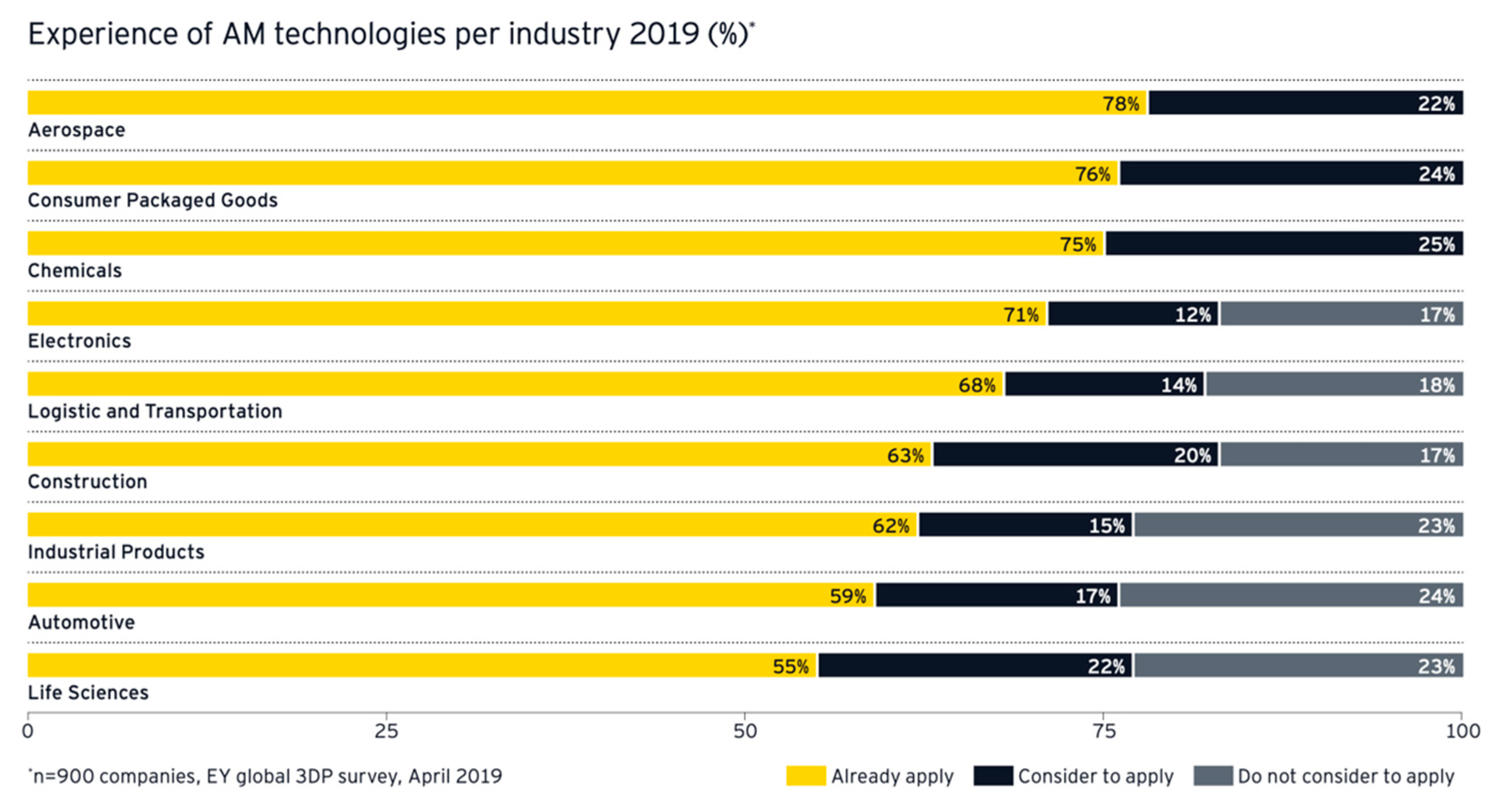
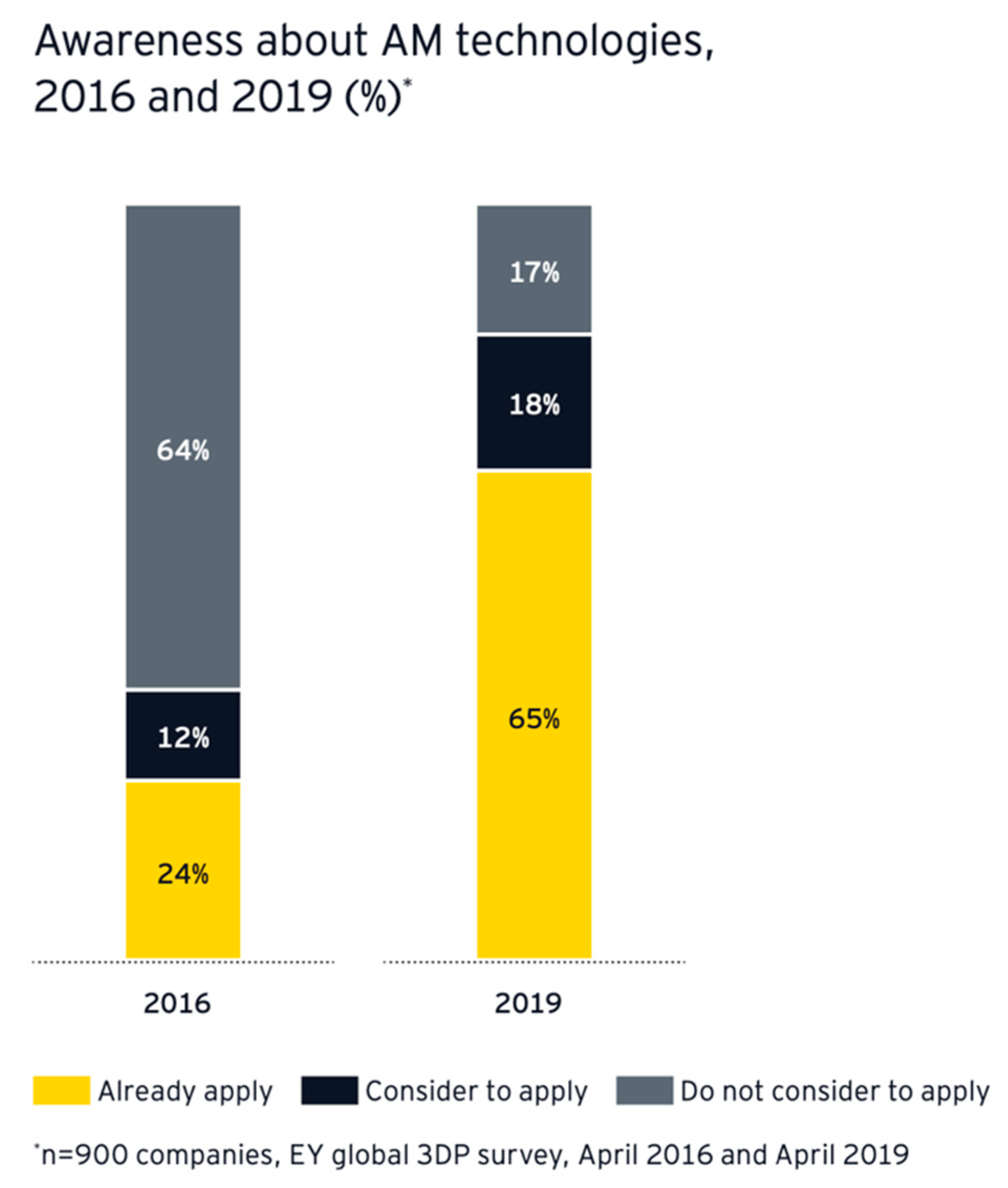
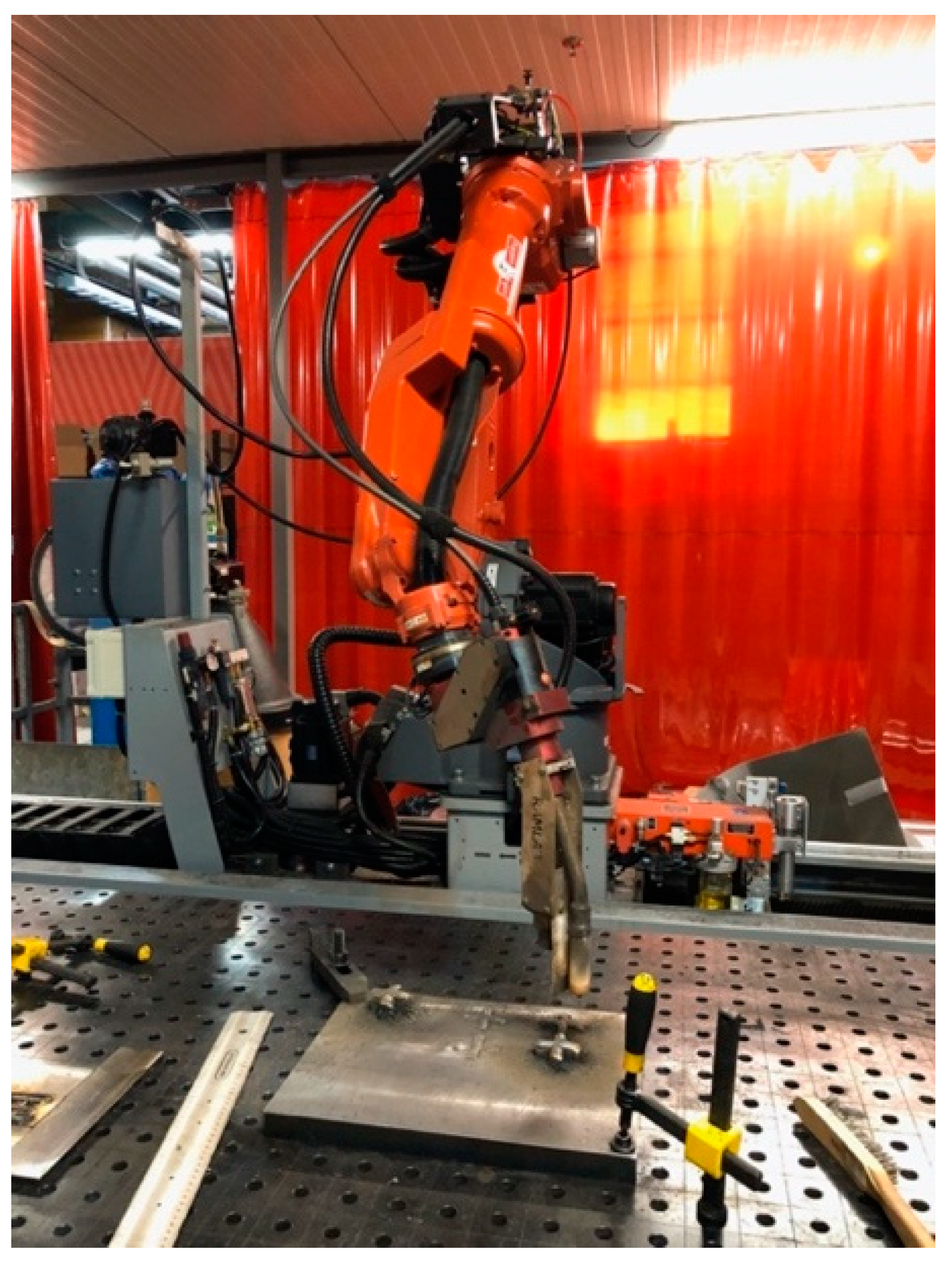
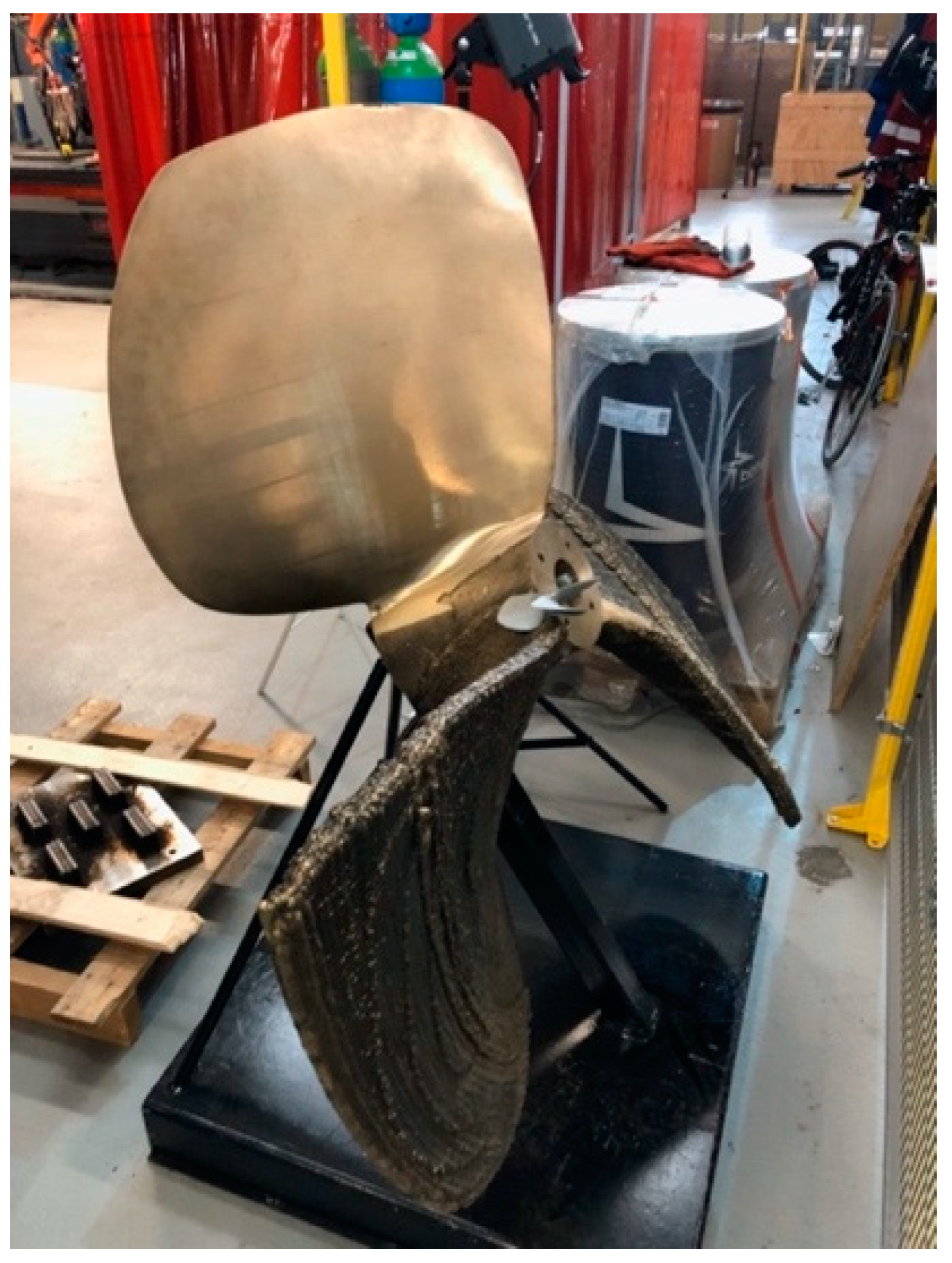
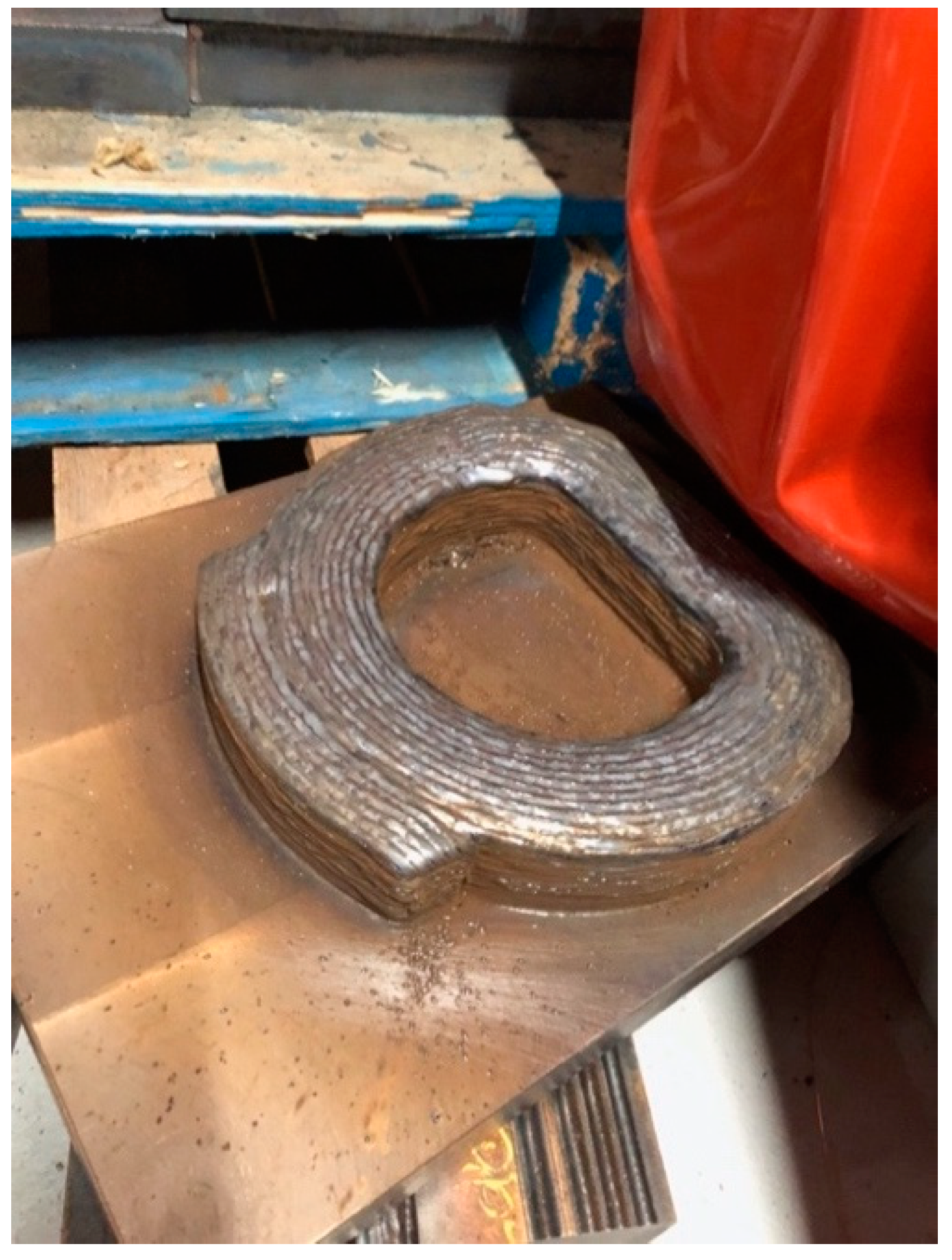
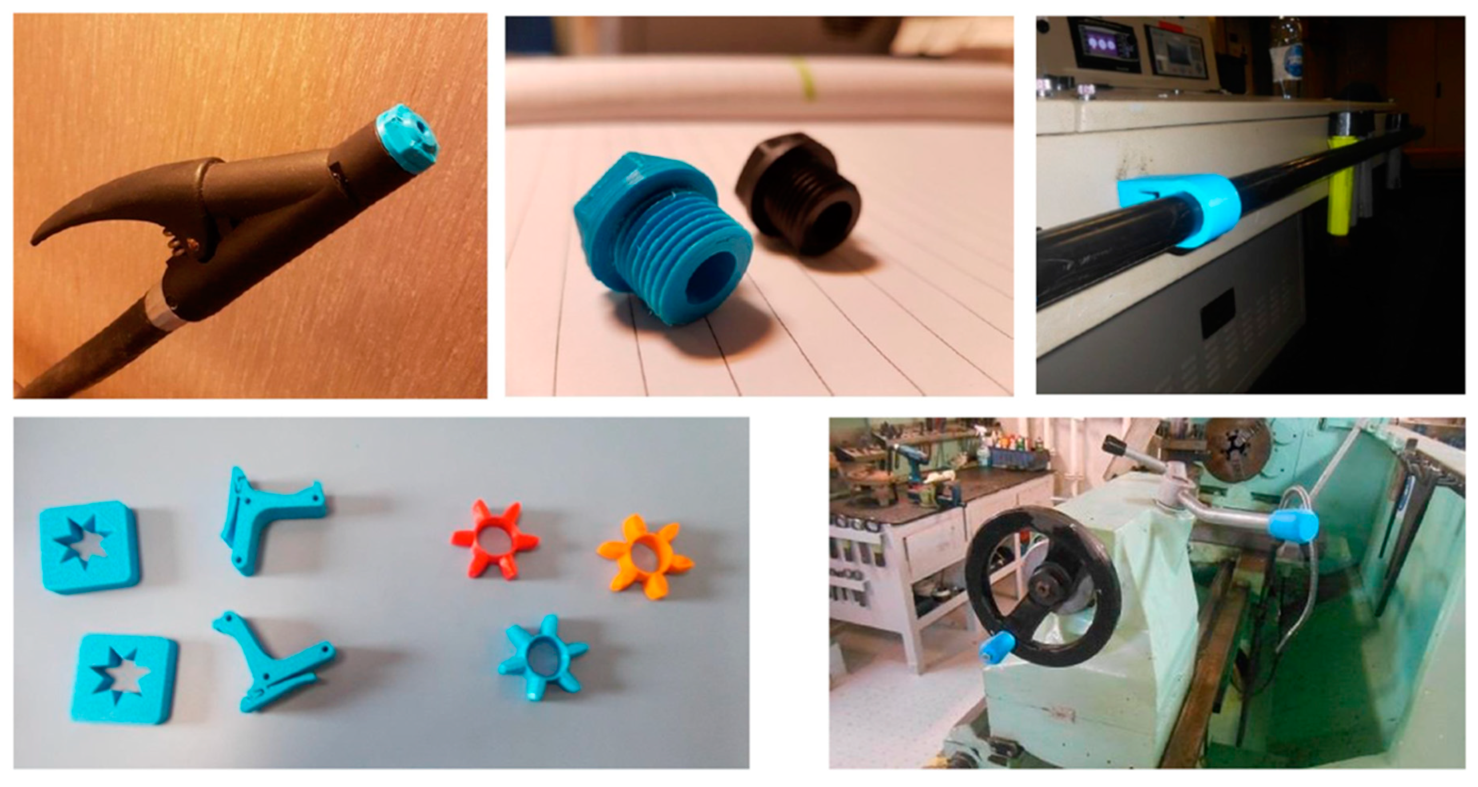
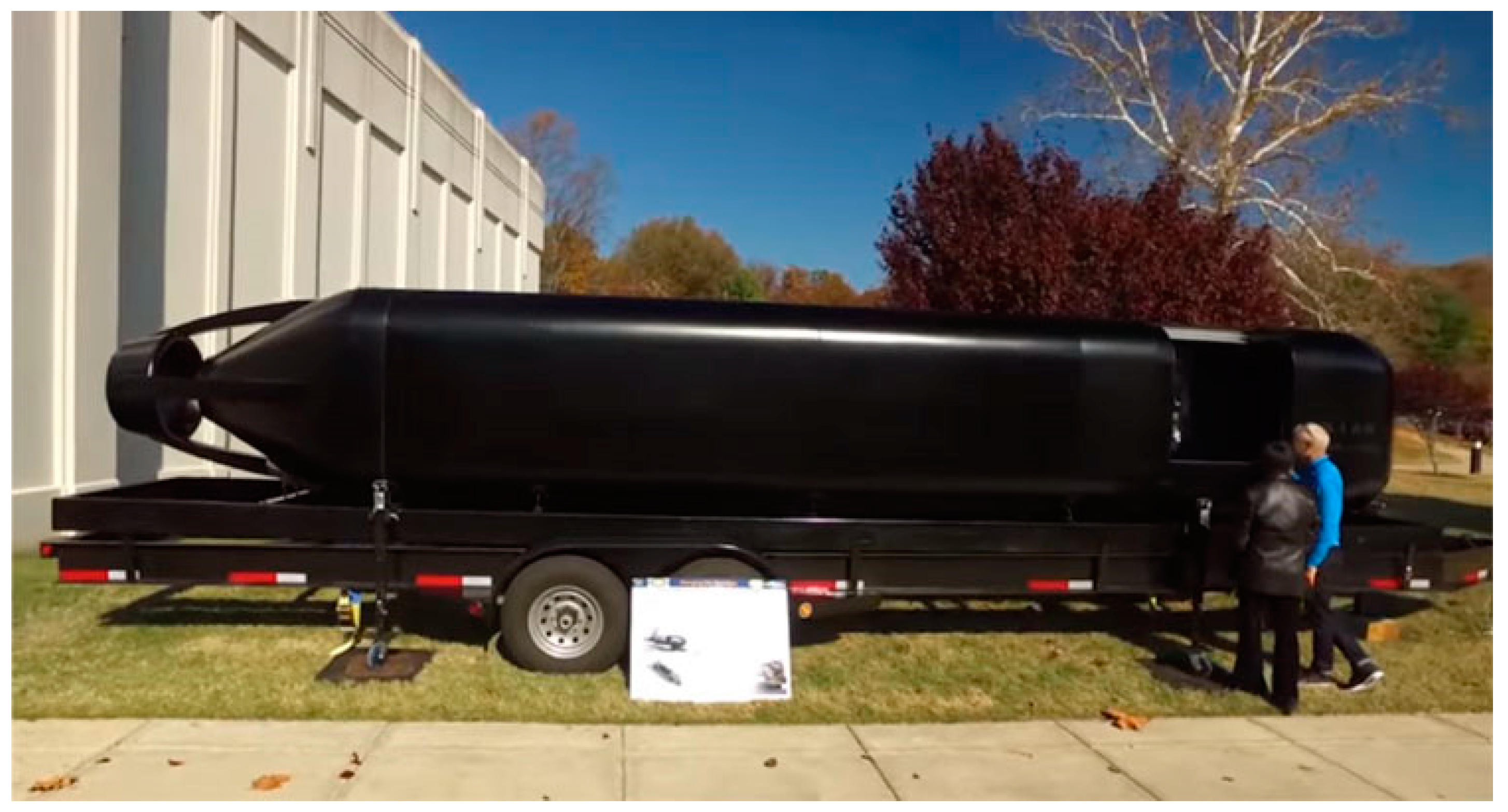
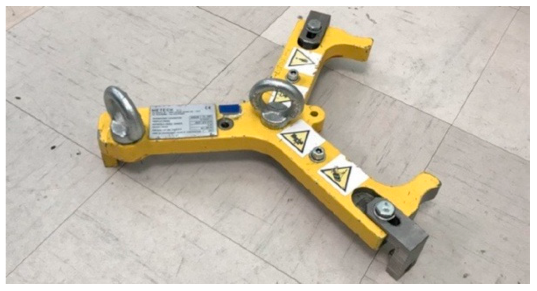
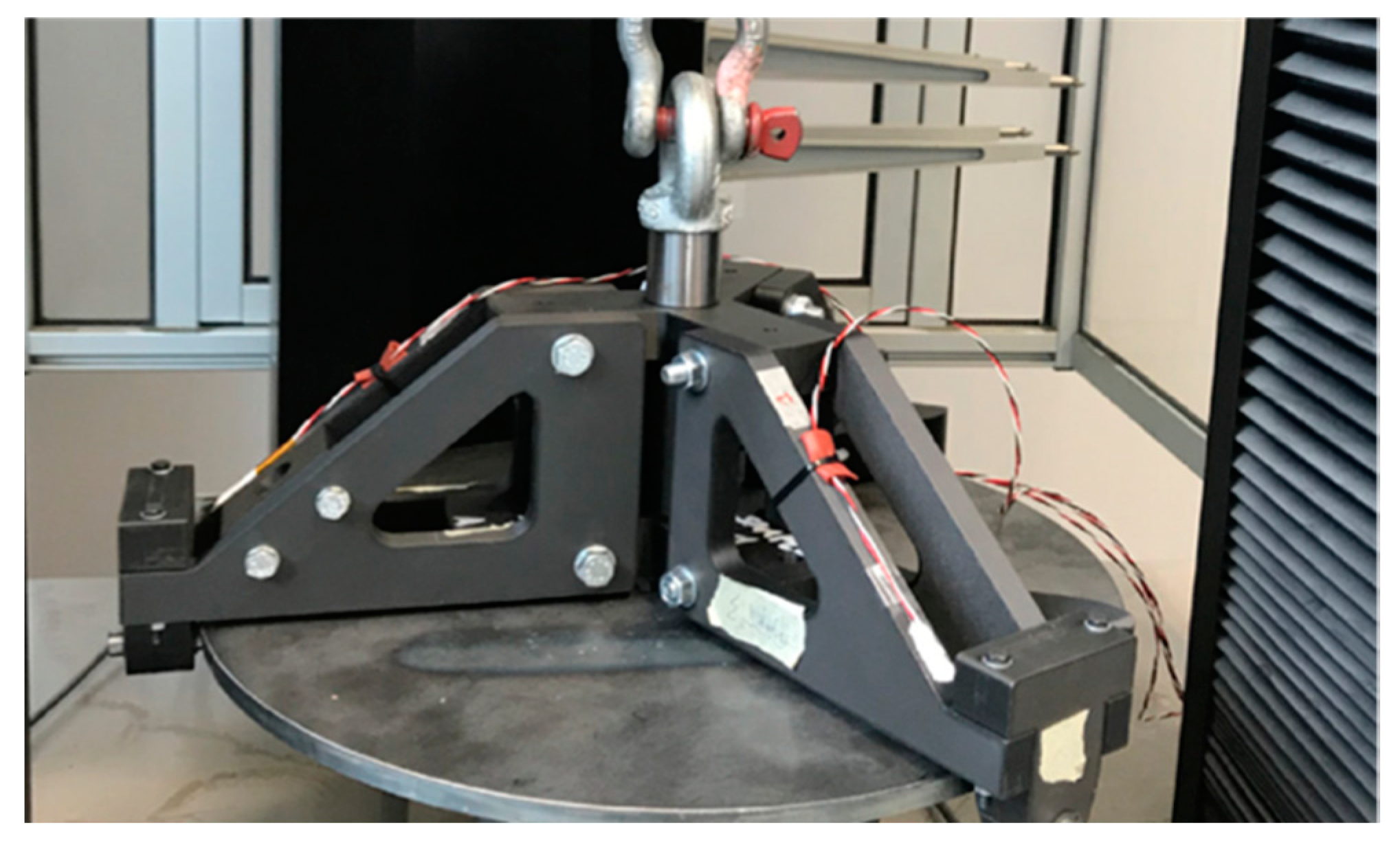
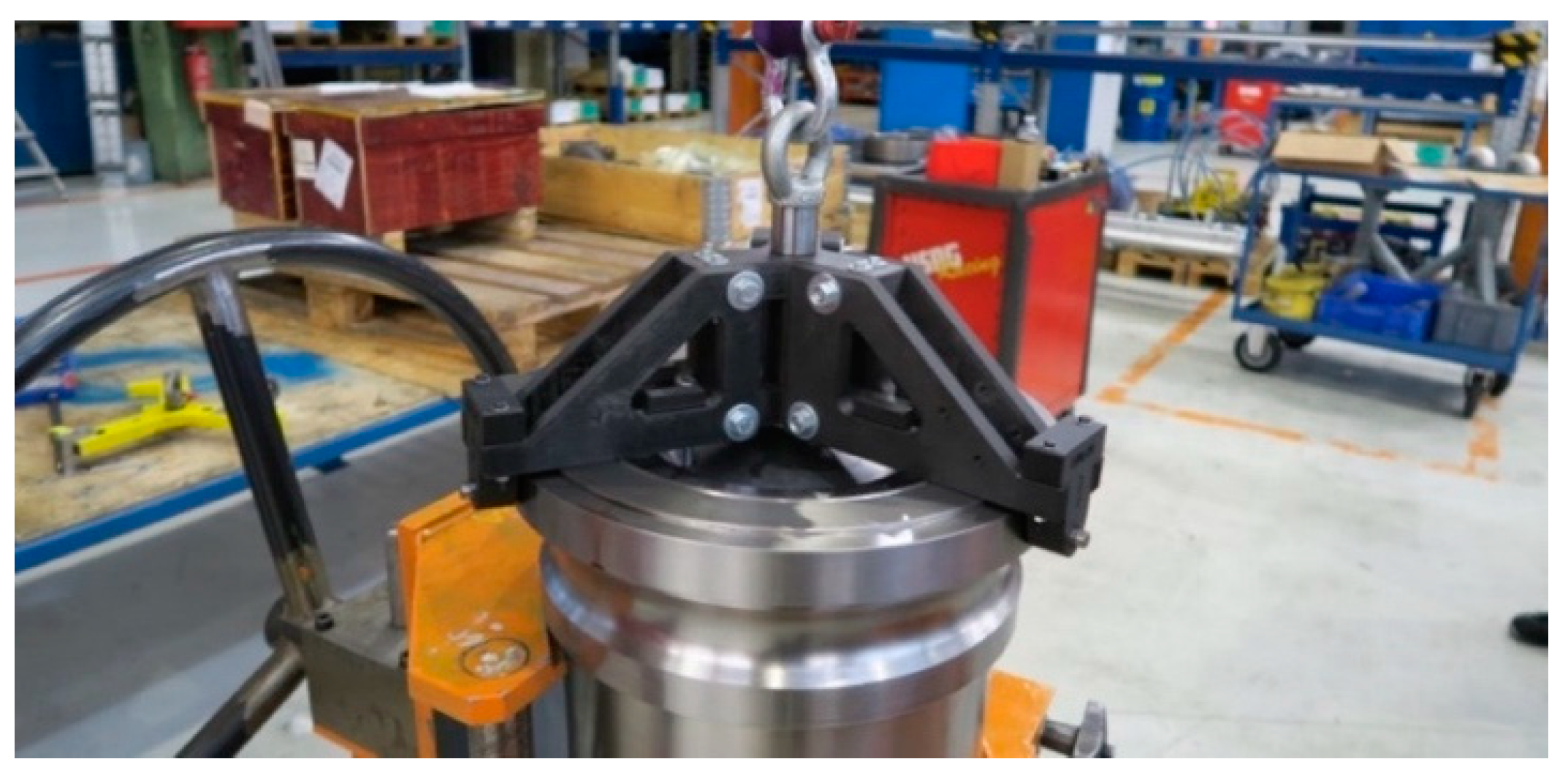
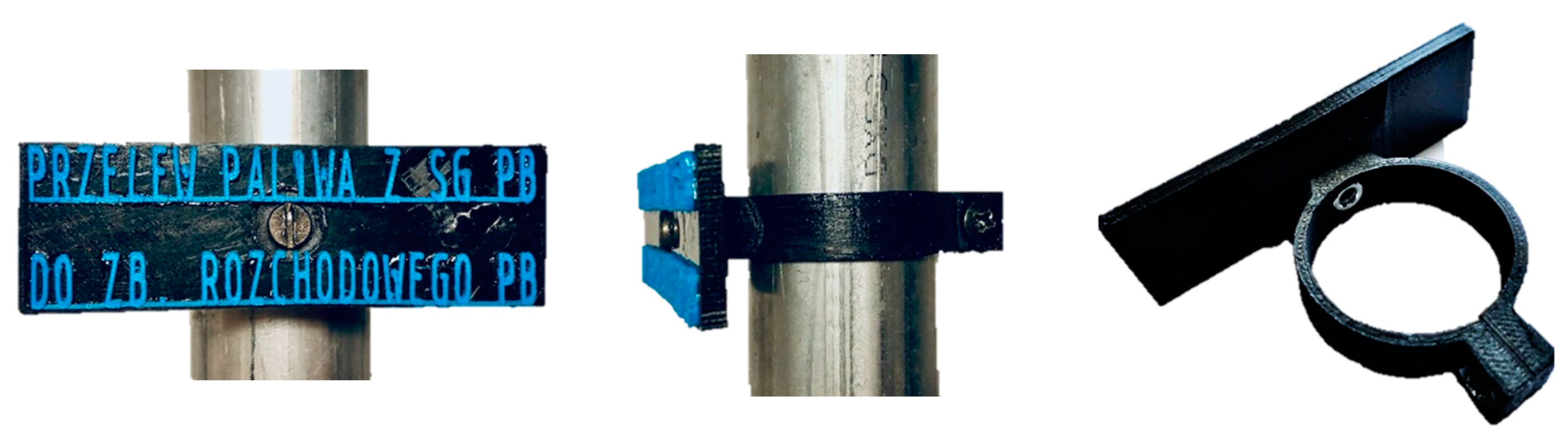
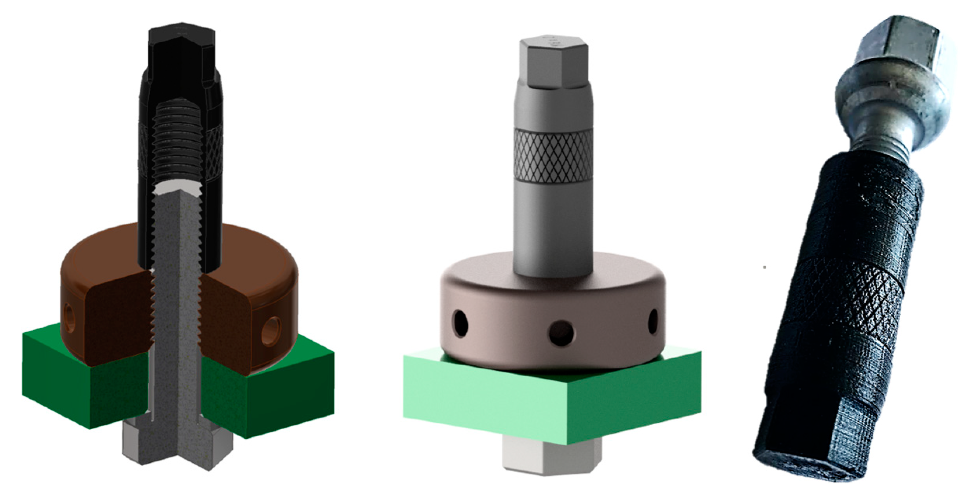
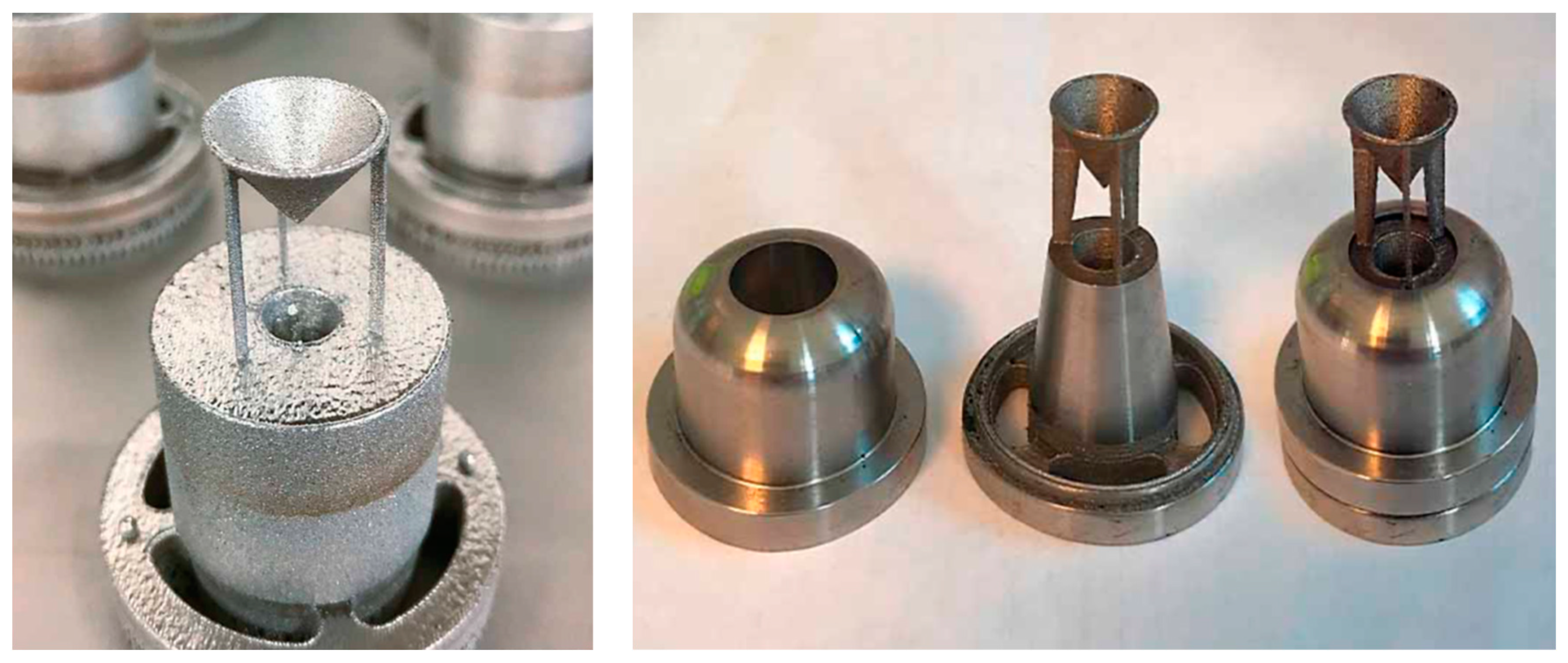
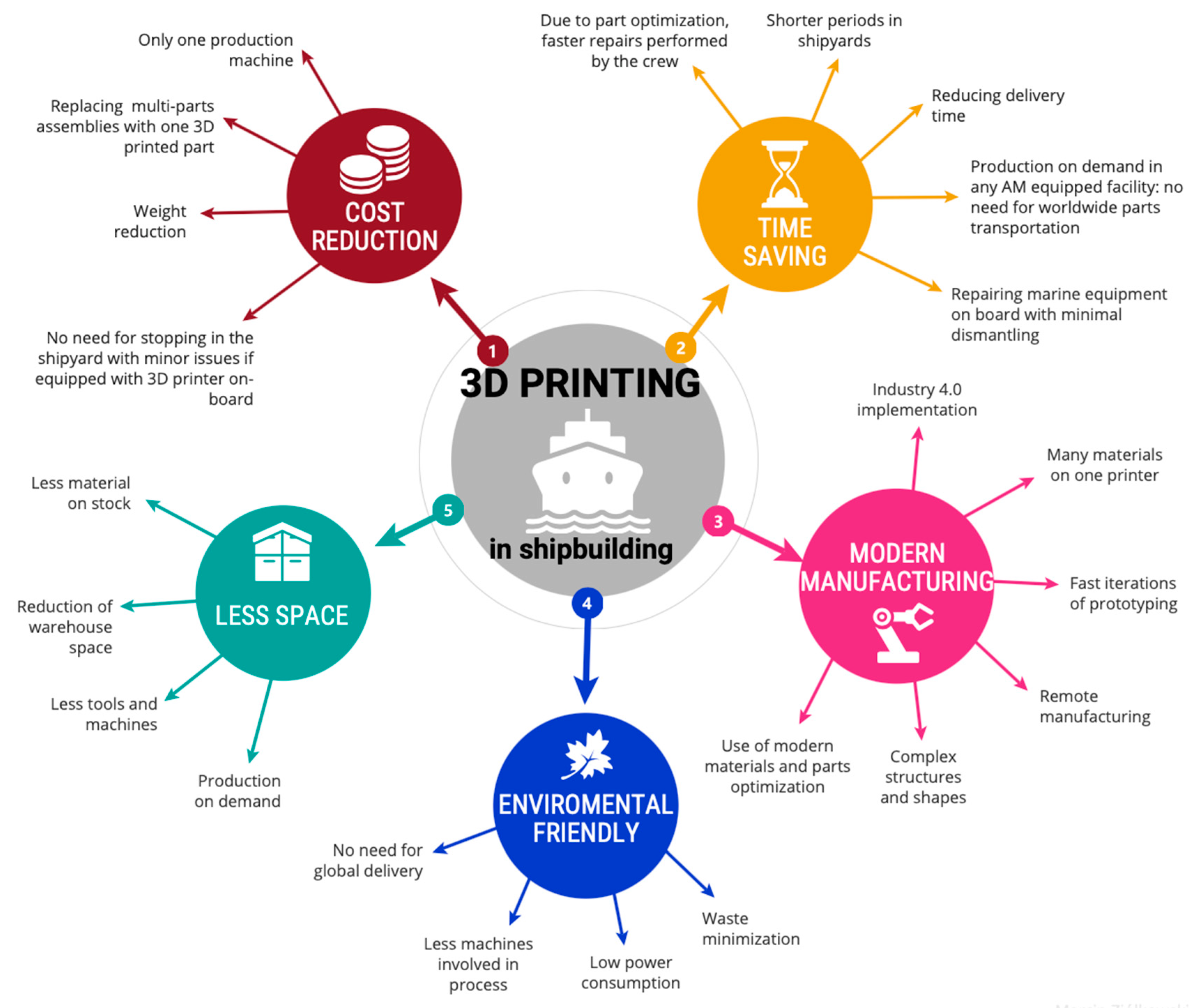
Table 1.
Comparison of selected mechanical properties of 3D printing and a solid sample of PA12 material [18].
Table 1.
Comparison of selected mechanical properties of 3D printing and a solid sample of PA12 material [18].
| X–Y Direction | Z Direction | Standard PA12 | |
|---|---|---|---|
| tensile strength (MPa) | 48 | 42 | 35–55 |
| modulus of elasticity (MPa) | 1650 | 1650 | 1270–2600 |
| elongation at break (%) | 18 | 4 | 120–300 |
Table 2.
Comparison of AlSi10Mg material, used for 3D printing, and similar A360 aluminum alloy, used in foundry [19].
Table 2.
Comparison of AlSi10Mg material, used for 3D printing, and similar A360 aluminum alloy, used in foundry [19].
| AlSi10Mg | A360 | |
|---|---|---|
| Yield point (MPa) (0.2% load) * | XY: 230 Z: 230 | 165 |
| Tensile strength (MPa) * | XY: 345 Z: 350 | 317 |
| Modulus of elasticity (GPa) * | XY: 70 Z: 60 | 71 |
| Elongation at break (%) * | XY: 12 Z: 11 | 3.5 |
| Hardness (HBW) ** | 119 | 75 |
| Fatigue strength (MPa) ** | 97 | 124 |
*: heat treatment—annealing at 300 °C for 2 h. **: Testing on made samples.
Table 3.
Division of parts into incremental methods [43].
Table 3.
Division of parts into incremental methods [43].
| Highly Feasible for 3D Printing without Class Certification | Highly Feasible for 3D Printing with Class Certification | Not Feasible for 3D Printing |
|---|---|---|
| Bearing shell | Air compressor elbow | Angular ball bearing |
| Compressor housing | Anti-Polishing ring | Anode |
| Top cover of fuel pump | Banjo plug | Band brake lining |
| Condenser/evaporator plate | Bearing bush | Bearing housing |
| Shaft | Bearing cover | Bolt reamer |
| Turbine diffuser | Bleed screw | Compressed sealing ring |
| Valve plug | Bursting disc | Compressor driving pulley |
| Bearing nut | Connecting rod | Coned disc spring |
| Compressor blade | Cooling water jacket | Crane shackle |
| Claw clutch | Crank pin | Dowel pin |
| Clutch shoe | Drive pinion | Fairlead |
| Connection nipple | Flange | Gasket |
| Couplings | Flexible coupling | Gear ring |
| Cylinder liner | Gear | Gland packing |
| Damper ring | Guide pin | Hexagon screw |
| Expansion joint | Handle axle | Impeller nut |
| Flywheel | Hatch cover packing | Key |
| Helical rotor | Impeller | Mooring winch drum |
| Nozzle ring | Needle roller bearing | Oil scraper ring (stuffing box) |
| Piston ring | Nozzle tip | Pipe clamp |
| Plunger barrel | O-ring | Piston crown |
| Rocker arm bracket | Oil slinger | Purifier bowl |
| Roller guide housing | Pintle bush | Screw |
| Rotary cup | Polyurethane buffer | Spring |
| Spindle guide | Quick acting cleats | Steel ball |
| Tapered bush | Retainer ring | V pulley |
| Thrust collar | Sea chest strainer | Valve spring |
| Thrust piece | Sea valve stem | Filter cartridge |
| Valve guide | Spiral gear | |
| Valve seat | Spring carrier | |
| Valve spindle | Swirler | |
| Worm gear | Thrust spindle | |
| Nut | Valve bridge | |
| Valve cotter | ||
| Washer | ||
| Wrist pin bushing | ||
| Cylinder cover | ||
| Disc valve | ||
| Valve rotator |
Table 4.
Examples of 3D printed elements, production times and savings [43].
Table 4.
Examples of 3D printed elements, production times and savings [43].
| Part Name | Original Material | Material Used for Printing | Printing Time | Average Savings on One Element | Photo of a Printed Item |
|---|---|---|---|---|---|
| Handwheel | Cast iron | Polyamide/Nylon | 7 h | 5.89 USD |  |
| Scupper plug | Brass and rubber | Polyamide/Nylon | 17 h | 4.50 USD |  |
| U-bolt | Galvanized steel | Resin | 2 h | 11.26 USD |  |
| Guide bar | Low alloyed Mn-V steel | Steel | 8 h | 1965 USD |  |
| Nut wing | Brass | Nylon reinforced with glass fiber | 5 h | 2.95 USD |  |
| Pipe cover | Brass | Polyamide/Nylon | 3 h | 3.96 USD |  |
| Bolt cover | ABS | Polyamide/Nylon | 19 h | 10.44 USD |  |
Table 5.
Advantages of AM implementation in shipbuilding.
| Criterion | Advantages of AM Implementation in Shipbuilding |
|---|---|
| Production volume | Volume adjusted to the current demand |
| Design and manufacturing process | New possibilities of parts optimization, remote manufacturing in the place where the ship is currently present |
| Prototyping | Ease of multi-iteration prototyping, possibility of creating new, customized materials |
| Item shape | Almost any shape and geometry, both external and internal |
| Versatility | 3D printers can produce any item from a wide range of materials and are applicable for many different geometries |
| Ease of use | Although the preparation for 3D printing is complex, production could be simplified to just starting the machine |
| Material consumption | Small loss for machining allowances and support structures |
| Benefits for crew | On-board manufacturing, less dismantling, parts reconditioning on-board |
| Benefits for shipowners | Savings on: custom duties, transportation, delays, manufacturer service |
| Benefits for manufacturers | Smaller storage space required, manufacturing on-demand, easier prototyping, new materials, savings on production machines, remote production, being more responsive to the customer needs |
| Benefits for shipyards | Less delays, parts on time, simpler logistics, shorter supply chains, possibility of producing extraordinary parts or spare parts for old vessels, no longer supported by manufacturer |
Publisher’s Note: MDPI stays neutral with regard to jurisdictional claims in published maps and institutional affiliations. |
© 2020 by the authors. Licensee MDPI, Basel, Switzerland. This article is an open access article distributed under the terms and conditions of the Creative Commons Attribution (CC BY) license (http://creativecommons.org/licenses/by/4.0/).
Share and Cite
MDPI and ACS Style
Ziółkowski, M.; Dyl, T. Possible Applications of Additive Manufacturing Technologies in Shipbuilding: A Review. Machines 2020, 8, 84. https://doi.org/10.3390/machines8040084
AMA Style
Ziółkowski M, Dyl T. Possible Applications of Additive Manufacturing Technologies in Shipbuilding: A Review. Machines. 2020; 8(4):84. https://doi.org/10.3390/machines8040084
Chicago/Turabian StyleZiółkowski, Marcin, and Tomasz Dyl. 2020. "Possible Applications of Additive Manufacturing Technologies in Shipbuilding: A Review" Machines 8, no. 4: 84. https://doi.org/10.3390/machines8040084
Note that from the first issue of 2016, this journal uses article numbers instead of page numbers. See further details here.