Lateral Angular Co-Extrusion: Geometrical and Mechanical Properties of Compound Profiles

 , ,
, , 
Abstract
:1. Introduction
- Co-extrusion of modified billets: The reinforcing element is contained in the billet and passes through the entire extrusion process. This variant includes the co-extrusion of metal matrix composites in which reinforcing particles such as Al2O3 were introduced in an aluminum billet by powder metallurgy [6] with the intention to achieve an even distribution of the reinforcing elements in the composite profile. A further variant is the local reinforcement of a billet, e.g., by inserting a round rod of a material of higher strength like titanium grade 2 into an aluminum billet and then extruding the materials simultaneously [7].
- Co-extrusion of conventional billets: In this case, the reinforcing element is introduced into the forming zone from outside the tool but is not plastically formed itself [8]. This process variant was investigated especially for the reinforcement of extruded profiles with steel or copper wires. By employing modified chamber tools [9], the wires were introduced into the forming zone via the support arms of the mandrel. Hence, the wire reinforcement was present in the longitudinal weld seams of the profiles only [10].
2. Materials and Methods
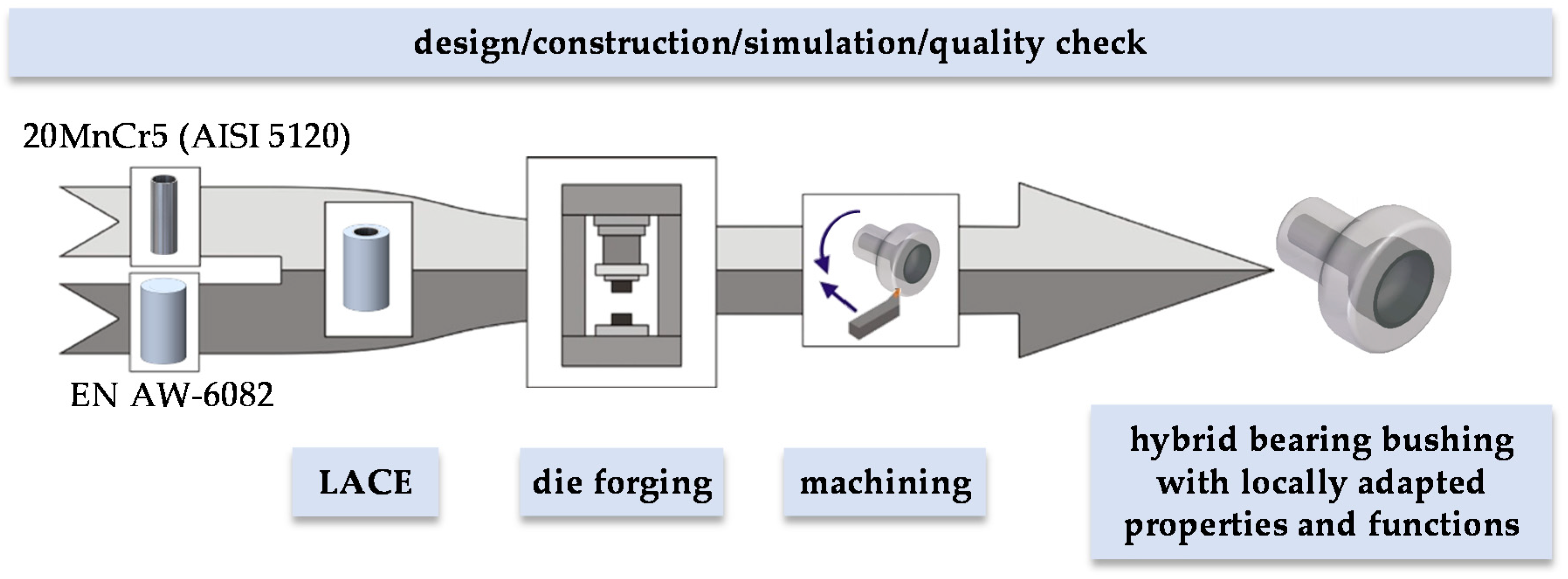
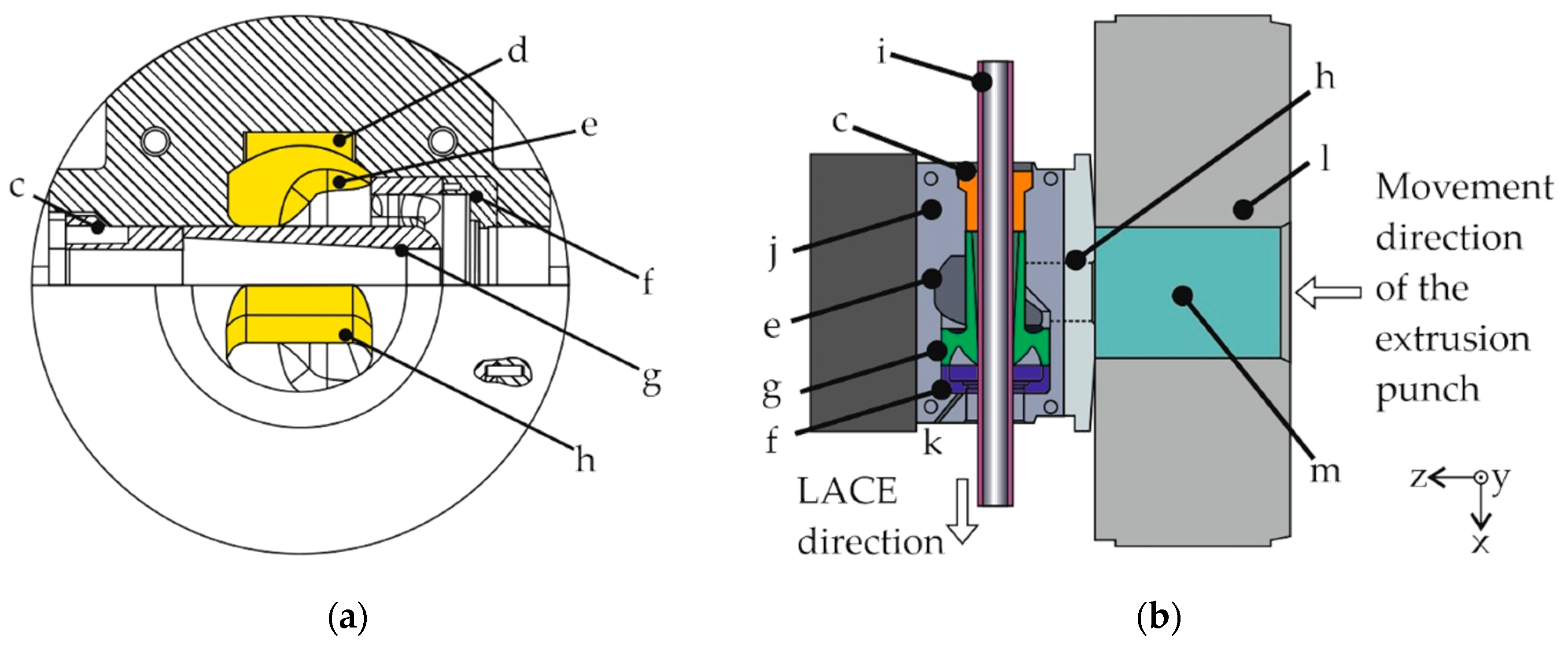
2.1. LACE Process
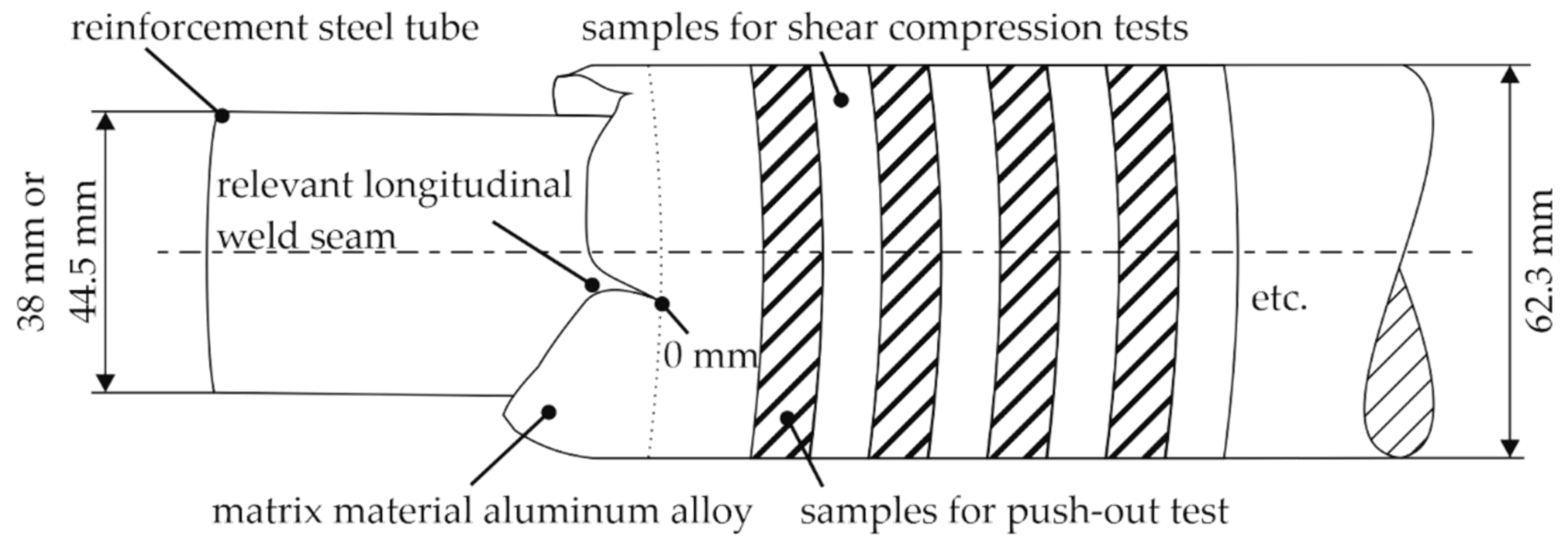
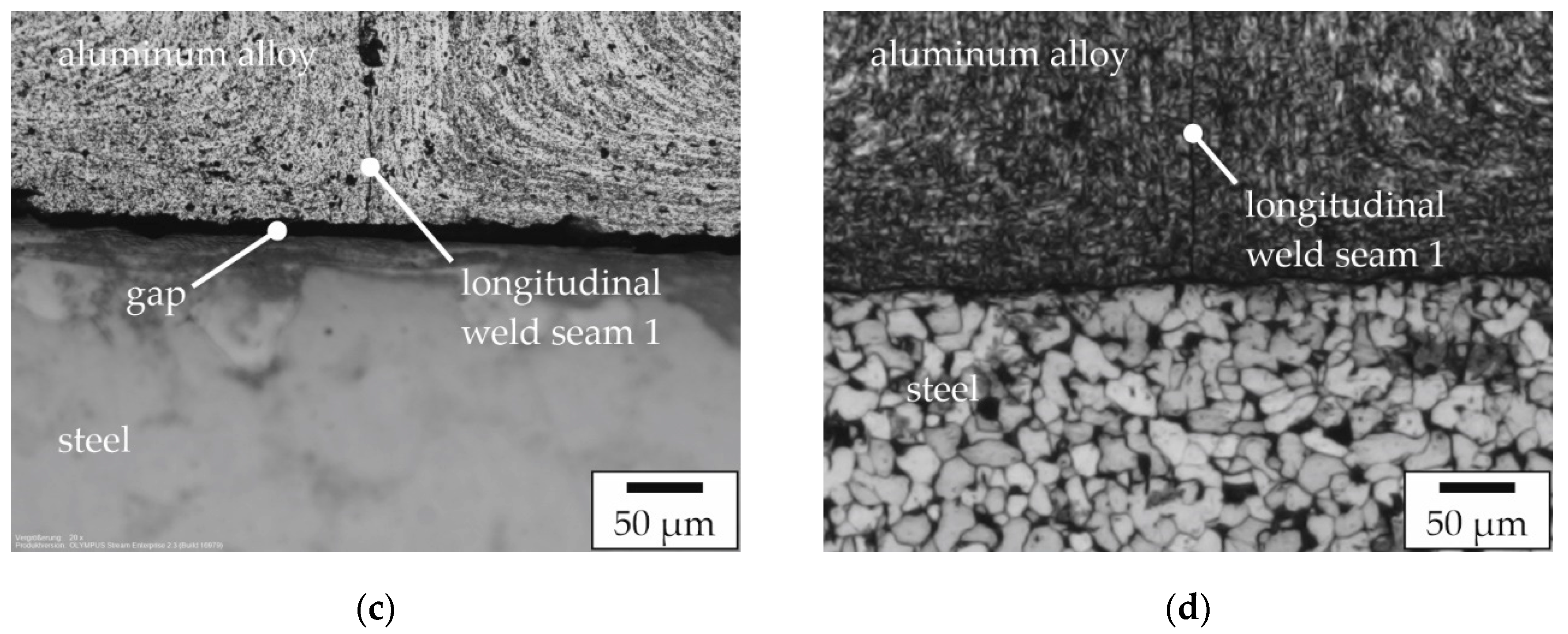
2.2. Metallographic Characterization
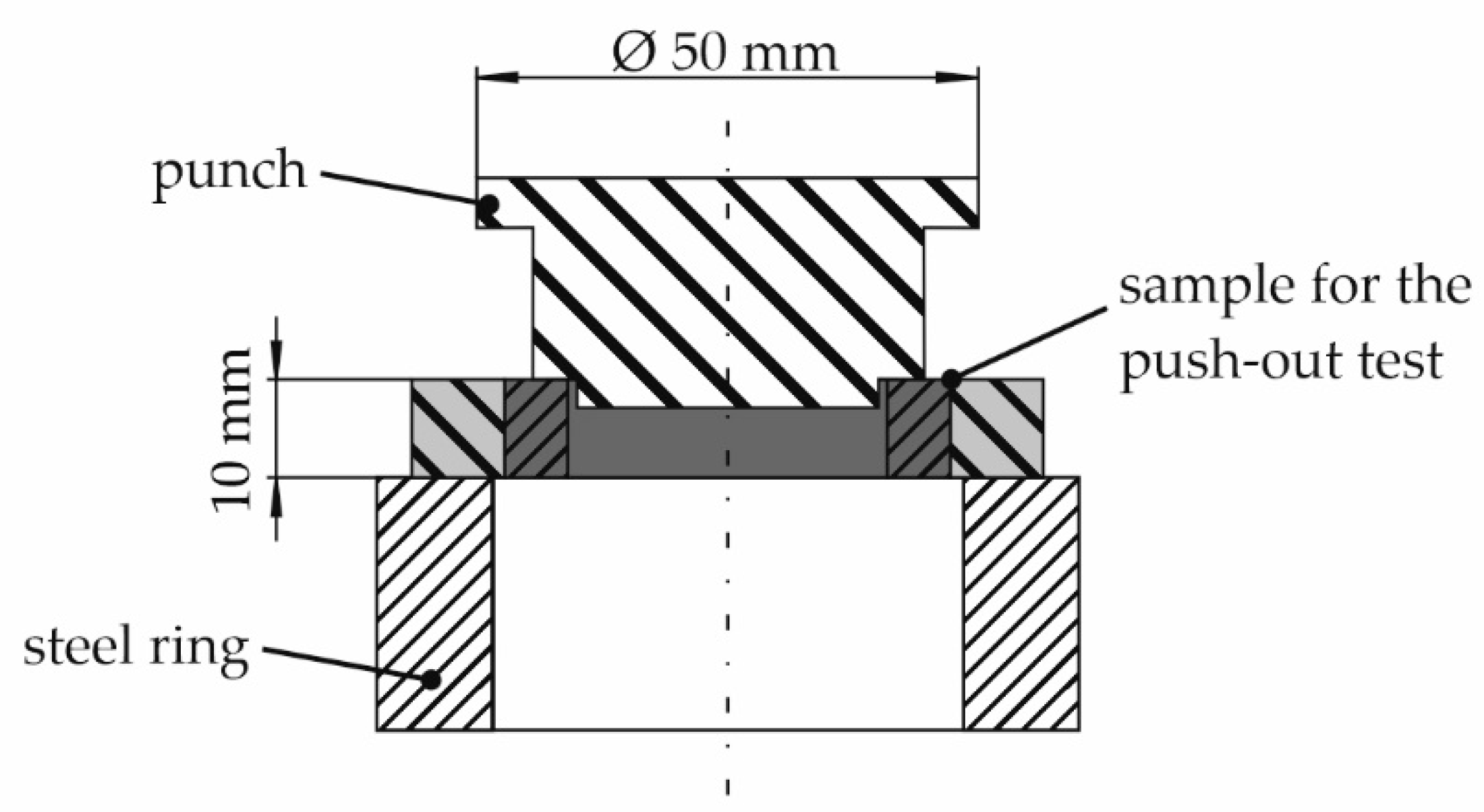
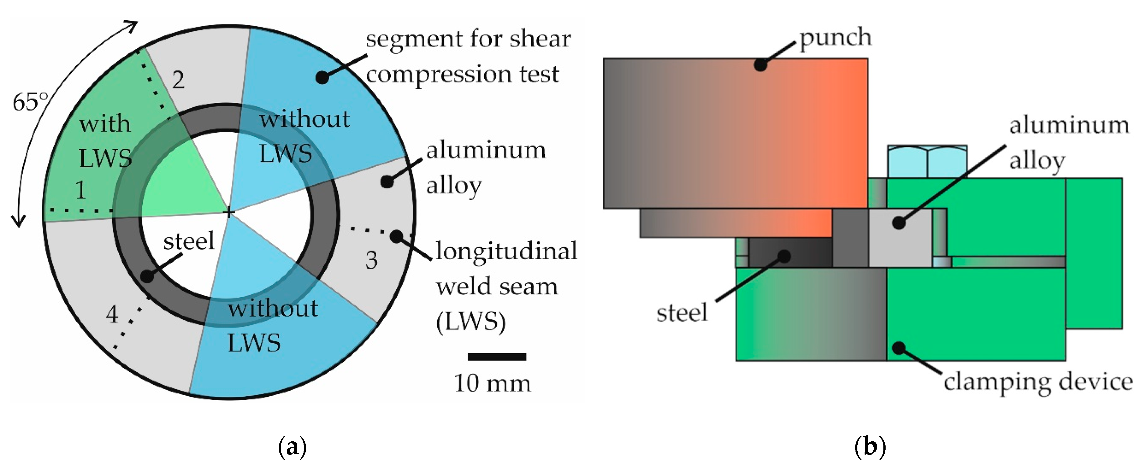
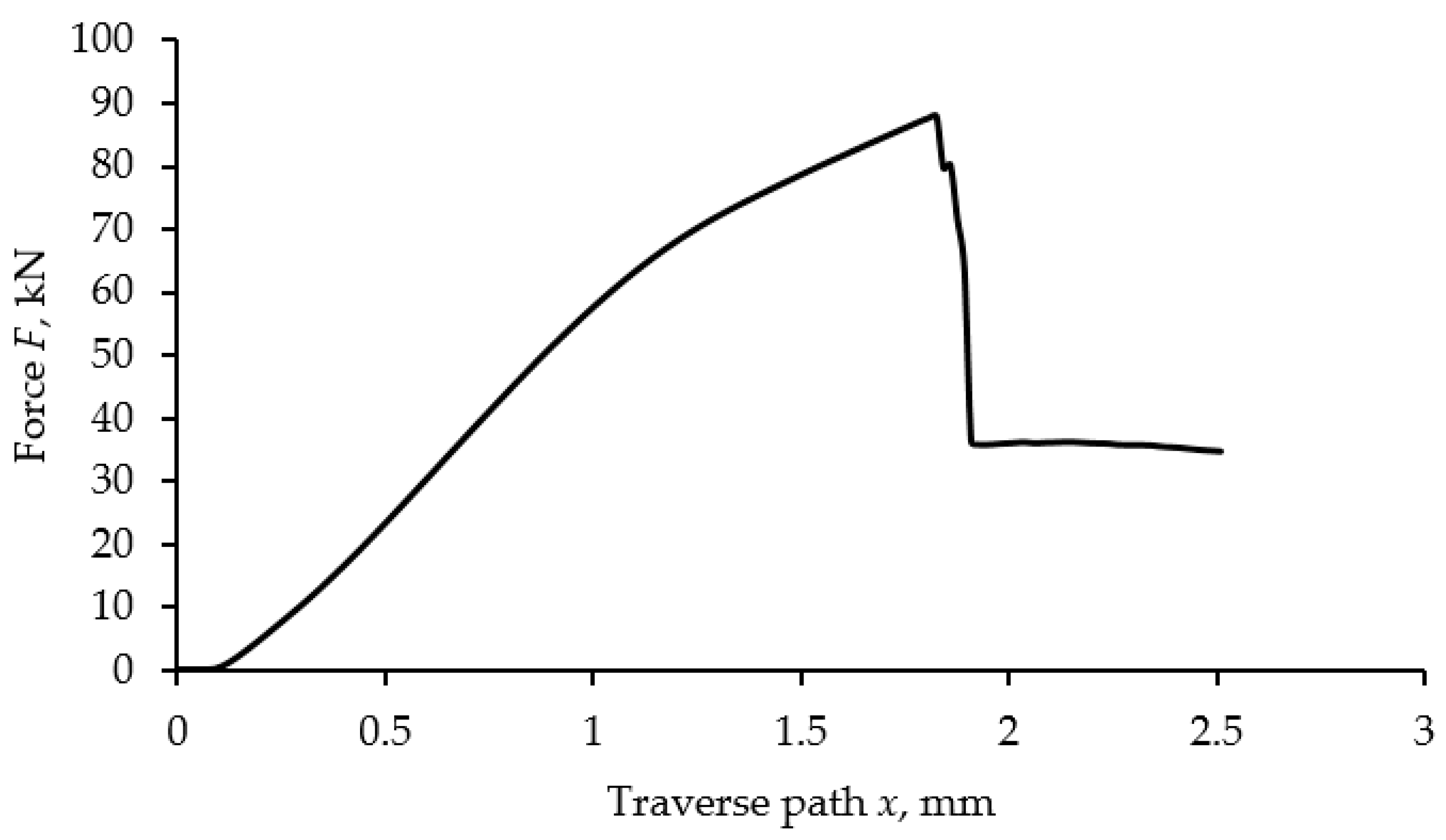
2.3. Push-Out Test and Shear Compression Test
3. Results
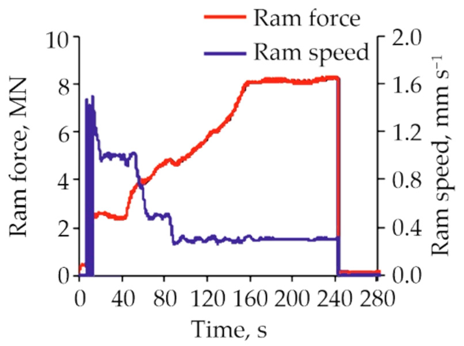
3.1. LACE Process
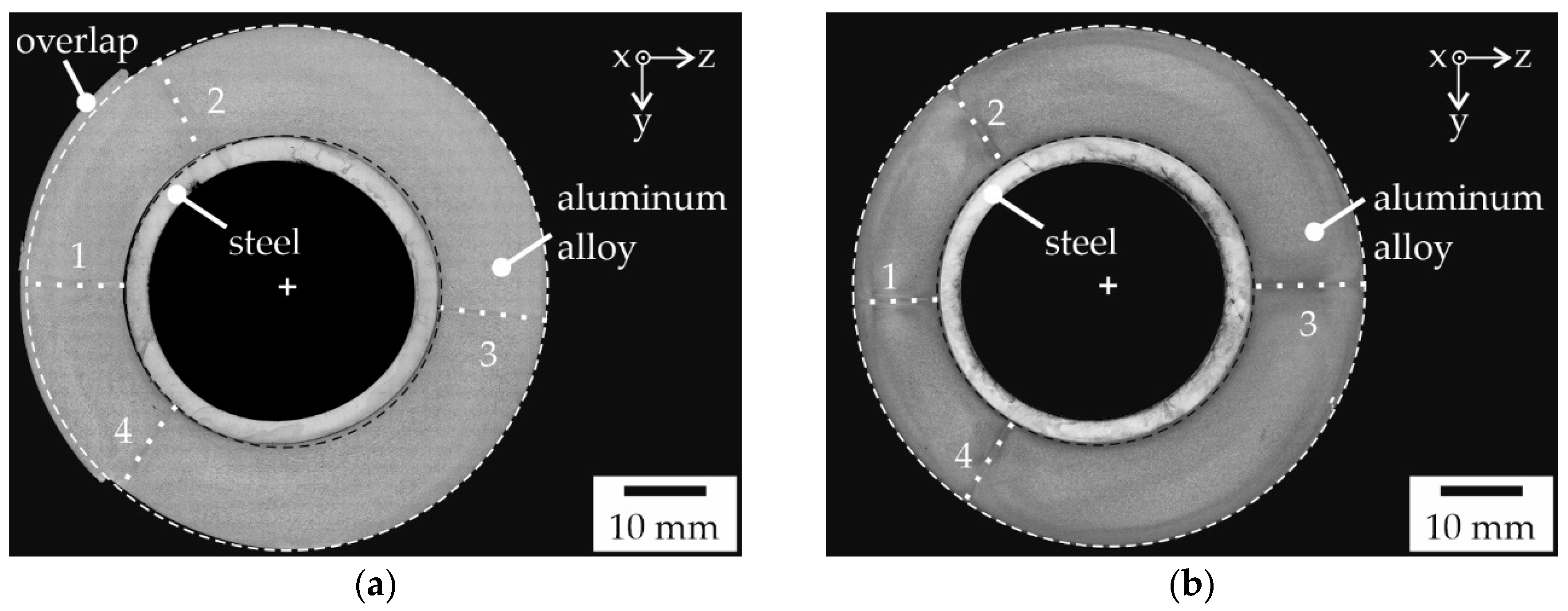
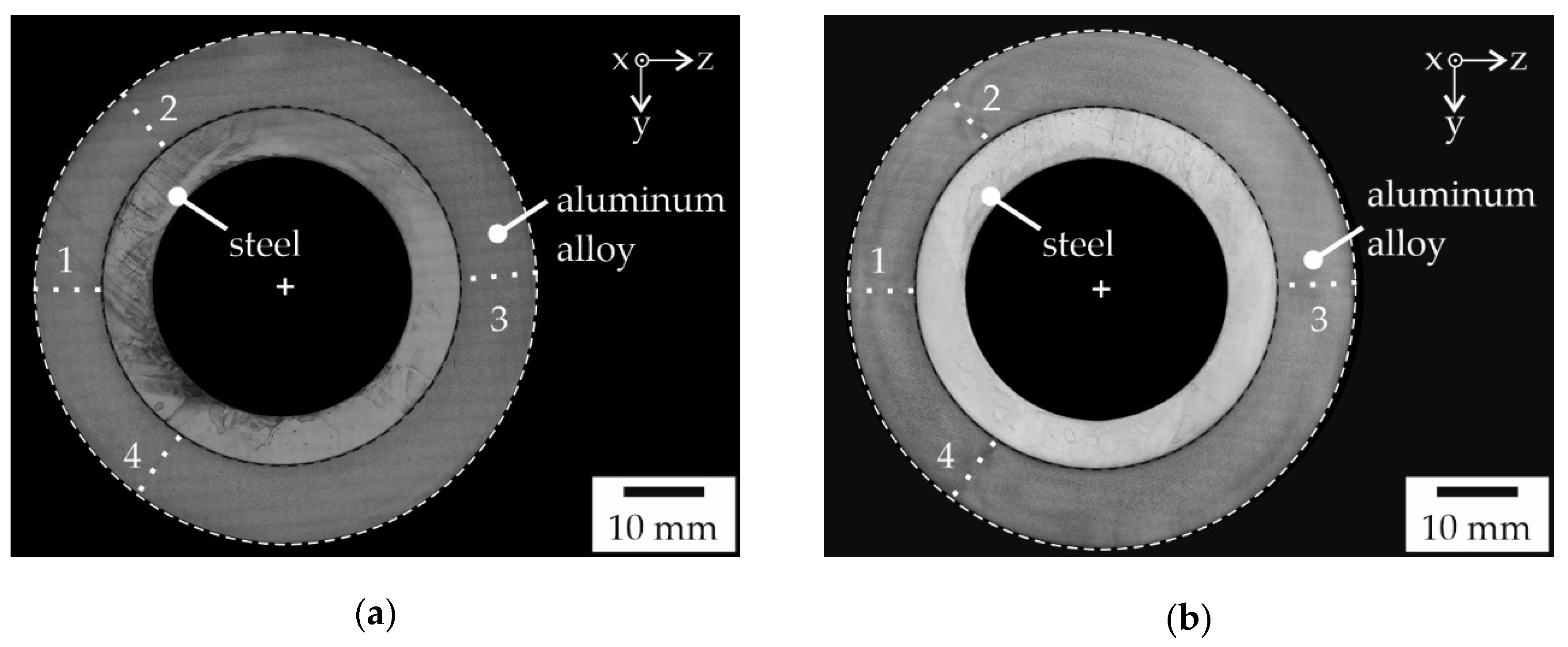
3.2. Metallographic Characterization
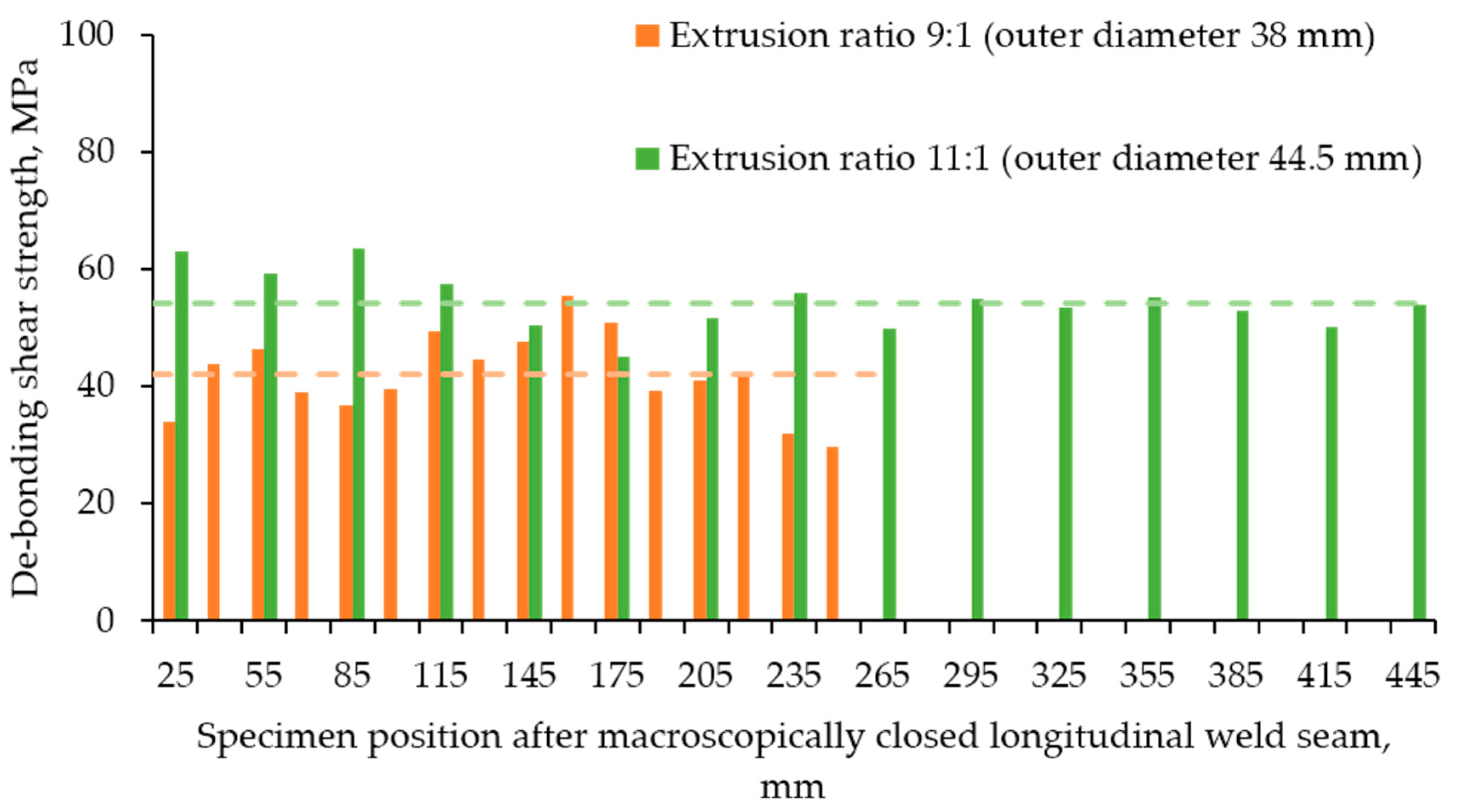
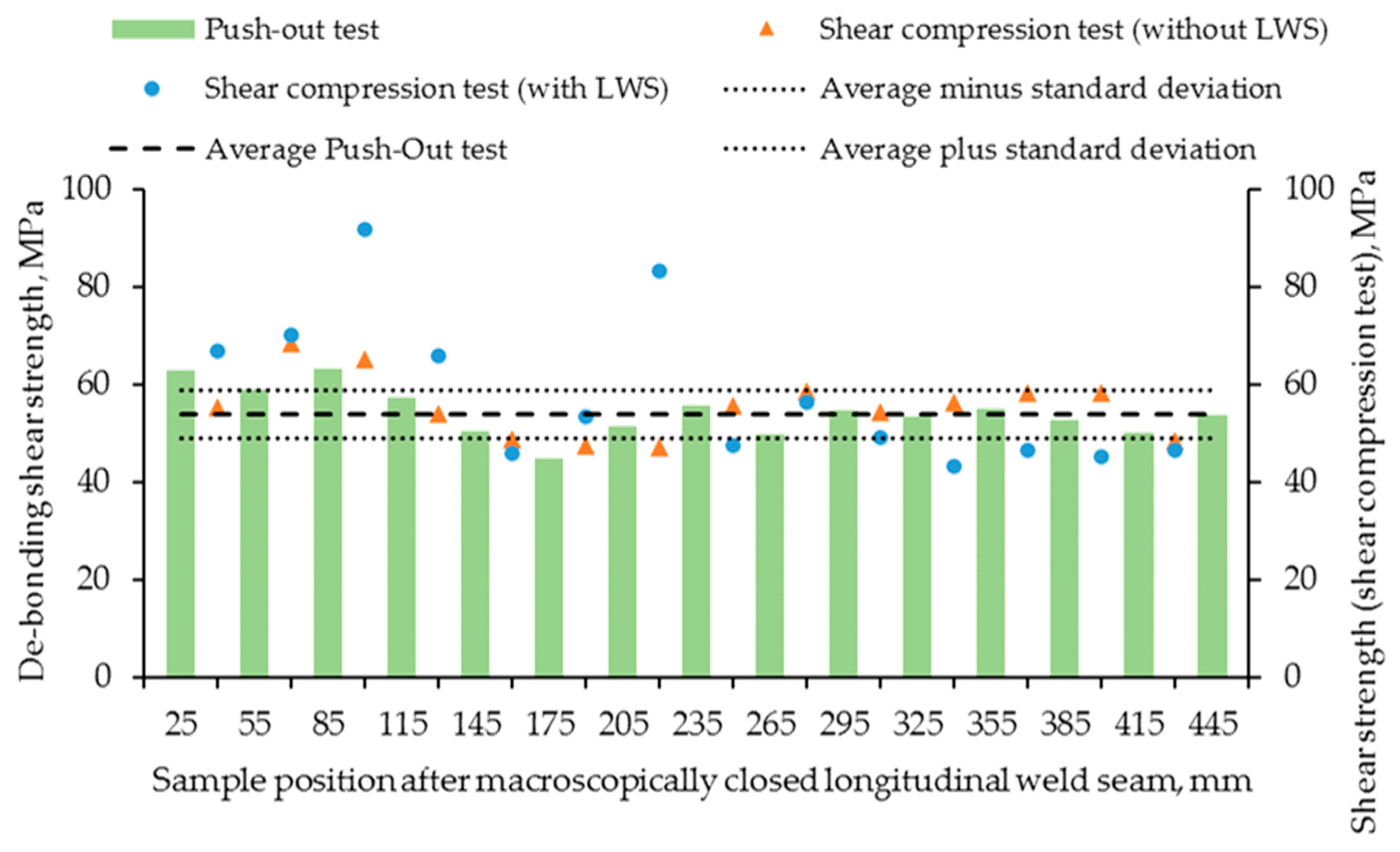
3.3. Mechanical Properties
4. Discussion
5. Conclusions and Outlook
Author Contributions
Funding
Acknowledgments
Conflicts of Interest
References
- Hirsch, J.; Hirsch, J. Aluminium in Innovative Light-Weight Car Design. Mater. Trans. 2011, 52, 818–824. [Google Scholar] [CrossRef] [Green Version]
- Merklein, M.; Johannes, M.; Lechner, M.; Kuppert, A. A review on tailored blanks–Production, applications and evaluation. J. Mater. Process. Technol. 2014, 241, 151–164. [Google Scholar] [CrossRef]
- Herbst, S.; Maier, H.J.; Nürnberger, F. Strategies for the Heat Treatment of Steel-Aluminium Hybrid Components. HTM J. Heat Treat. Mater. 2018, 73, 268–282. [Google Scholar] [CrossRef]
- Agudo, L.; Jank, N.; Wagner, J.; Weber, S.; Schmaranzer, C.; Arenholz, E.; Bruckner, J.; Hackl, H.; Pyzalla, A. Investigation of microstructure and mechanical properties of steel-aluminium joints produced by metal arc joining. Steel Res. Int. 2008, 79, 530–535. [Google Scholar] [CrossRef]
- Bauser, M.; Sauer, G.; Siegert, K. Strangpressen; Aluminium-Verlag: Düsseldorf, German, 2001; ISBN 3-87017-249-5. [Google Scholar]
- Foydl, A.; Haase, M.; Ben Khalifa, N.; Tekkaya, A. Co-extrusion of discontinuously, non-centric steel-reinforced aluminum. In Proceedings of the the 14th International Esaform Conference on Material Forming, Esaform 2011, Menary, Gary, 27–29 April 2011; pp. 443–448. [Google Scholar]
- Dietrich, D.; Grittner, N.; Mehner, T.; Nickel, D.; Schaper, M.; Maier, H.J.; Lampke, T. Microstructural evolution in the bonding zones of co-extruded aluminium/titanium. J. Mater. Sci. 2013, 49, 2442–2455. [Google Scholar] [CrossRef]
- Kleiner, M.; Schomäcker, M.; Schikorra, M.; Klaus, A. Herstellung verbundverstärkter Aluminiumprofile für ultraleichte Tragwerke durch Strangpressen. Mater. Werkst. 2004, 35, 431–439. [Google Scholar] [CrossRef]
- Pietzka, D.; Ben Khalifa, N.; Gerke, S.; Tekkaya, A. Composite extrusion of thin aluminum profiles with high reinforcing volume. Key Eng. Mater. 2013, 554, 801–808. [Google Scholar] [CrossRef]
- Weidenmann, K.A. Verbundstrangpressen Mit Modifizierten Kammerwerkzeugen: Werkstofftechnik, Fertigungstechnik, Simulation. Karlsruhe; KIT Scientific Publishing: Karlsruhe, Germany, 2012; ISBN 978-3-86644-890-2. [Google Scholar]
- Grittner, N.; Striewe, B.; Von Hehl, A.; Engelhardt, M.; Klose, C.; Nürnberger, F. Characterization of the interface of co-extruded asymmetric aluminum-titanium composite profiles. Mater. Werkst. 2014, 45, 1054–1060. [Google Scholar] [CrossRef]
- Thürer, S.E.; Uhe, J.; Golovko, O.; Bonk, C.; Bouguecha, A.; Klose, C.; Behrens, B.-A.; Maier, H.J. Co-extrusion of semi-finished aluminium-steel compounds. In Proceedings of the 20th International Esaform Conference on Material Forming: Esaform 2017, Dublin, Ireland, 26–28 April 2017; p. 140002. [Google Scholar]
- Behrens, B.-A.; Klose, C.; Thürer, S.E.; Heimes, N.; Uhe, J. Numerical modeling of the development of intermetallic layers between aluminium and steel during co-extrusion. In Proceedings of the 22nd International Esaform Conference on Material Forming: Esaform 2019, Vitoria-Gasteiz, Spain, 8–10 May 2019; p. 040029. [Google Scholar]
- Behrens, B.-A.; Kosch, K.-G. Development of the heating and forming strategy in compound forging of hybrid steel-aluminum parts. Mater. Werkst. 2011, 42, 973–978. [Google Scholar] [CrossRef]
- Weidenmann, K.; Kerscher, E.; Schulze, V.; Löhe, D. Characterization of the interfacial properties of compound-extruded lightweight profiles using the push-out-technique. Mater. Sci. Eng. A 2006, 424, 205–211. [Google Scholar] [CrossRef]
- Behrens, B.-A.; Sokolinskaja, V.; Chugreeva, A.; Diefenbach, J.; Thürer, S.; Bohr, D. Investigation into the bond strength of the joining zone of compound forged hybrid aluminium-steel bearing bushing. In Proceedings of the 22nd International Esaform Conference on Material Forming: Esaform 2019, Vitoria-Gasteiz, Spain, 8–10 May 2019; p. 040028. [Google Scholar]
- Pietzka, D. Erweiterung des Verbundstrangpressens zu Höheren Verstärkungsanteilen und Funktionalen Verbunden; Kleiner, M., Ed.; Shaker Verlag: Düren/Maastricht, Germany, 2014. [Google Scholar]
- Thürer, S.E.; Uhe, J.; Golovko, O.; Bonk, C.; Bouguecha, A.; Behrens, B.-A.; Klose, C. Mechanical properties of co-extruded aluminium-steel compounds. Key Eng. Mater. 2017, 742, 512–519. [Google Scholar] [CrossRef] [Green Version]
- VDI-Fachbereich Produktentwicklung und Mechatronik. Methodische Auswahl Fester Verbindungen-Systematik, Konstruktionskataloge, Arbeitshilfen; VDI-Gesellschaft Produkt- und Prozessgestaltung: Düsseldorf, Germany, 2004. [Google Scholar]
- Weidenmann, K.A.; Kerscher, E.; Schulze, V.; Löhe, D. Grenzflächen in verbundstrangpressprofilen auf aluminiumbasis mit verschiedenen verstärkungselementen. In Praktische Metallographie Sonderband 37; Göken, M., Ed.; KIT Scientific Publishing: Karlsruhe, Germany, 2005; pp. 131–136. [Google Scholar]


© 2020 by the authors. Licensee MDPI, Basel, Switzerland. This article is an open access article distributed under the terms and conditions of the Creative Commons Attribution (CC BY) license (http://creativecommons.org/licenses/by/4.0/).
Share and Cite
Thürer, S.E.; Peddinghaus, J.; Heimes, N.; Bayram, F.C.; Bal, B.; Uhe, J.; Behrens, B.-A.; Maier, H.J.; Klose, C. Lateral Angular Co-Extrusion: Geometrical and Mechanical Properties of Compound Profiles. Metals 2020, 10, 1162. https://doi.org/10.3390/met10091162
Thürer SE, Peddinghaus J, Heimes N, Bayram FC, Bal B, Uhe J, Behrens B-A, Maier HJ, Klose C. Lateral Angular Co-Extrusion: Geometrical and Mechanical Properties of Compound Profiles. Metals. 2020; 10(9):1162. https://doi.org/10.3390/met10091162
Chicago/Turabian StyleThürer, Susanne Elisabeth, Julius Peddinghaus, Norman Heimes, Ferdi Caner Bayram, Burak Bal, Johanna Uhe, Bernd-Arno Behrens, Hans Jürgen Maier, and Christian Klose. 2020. "Lateral Angular Co-Extrusion: Geometrical and Mechanical Properties of Compound Profiles" Metals 10, no. 9: 1162. https://doi.org/10.3390/met10091162