
Investigation of the Weld Properties of Dissimilar S32205 Duplex Stainless Steel with AISI 304 Steel Joints Produced by Arc Stud Welding


Abstract
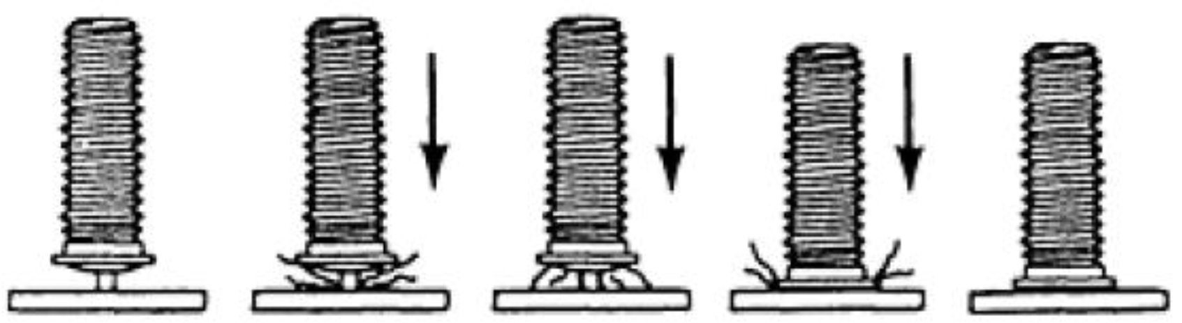
:1. Introduction
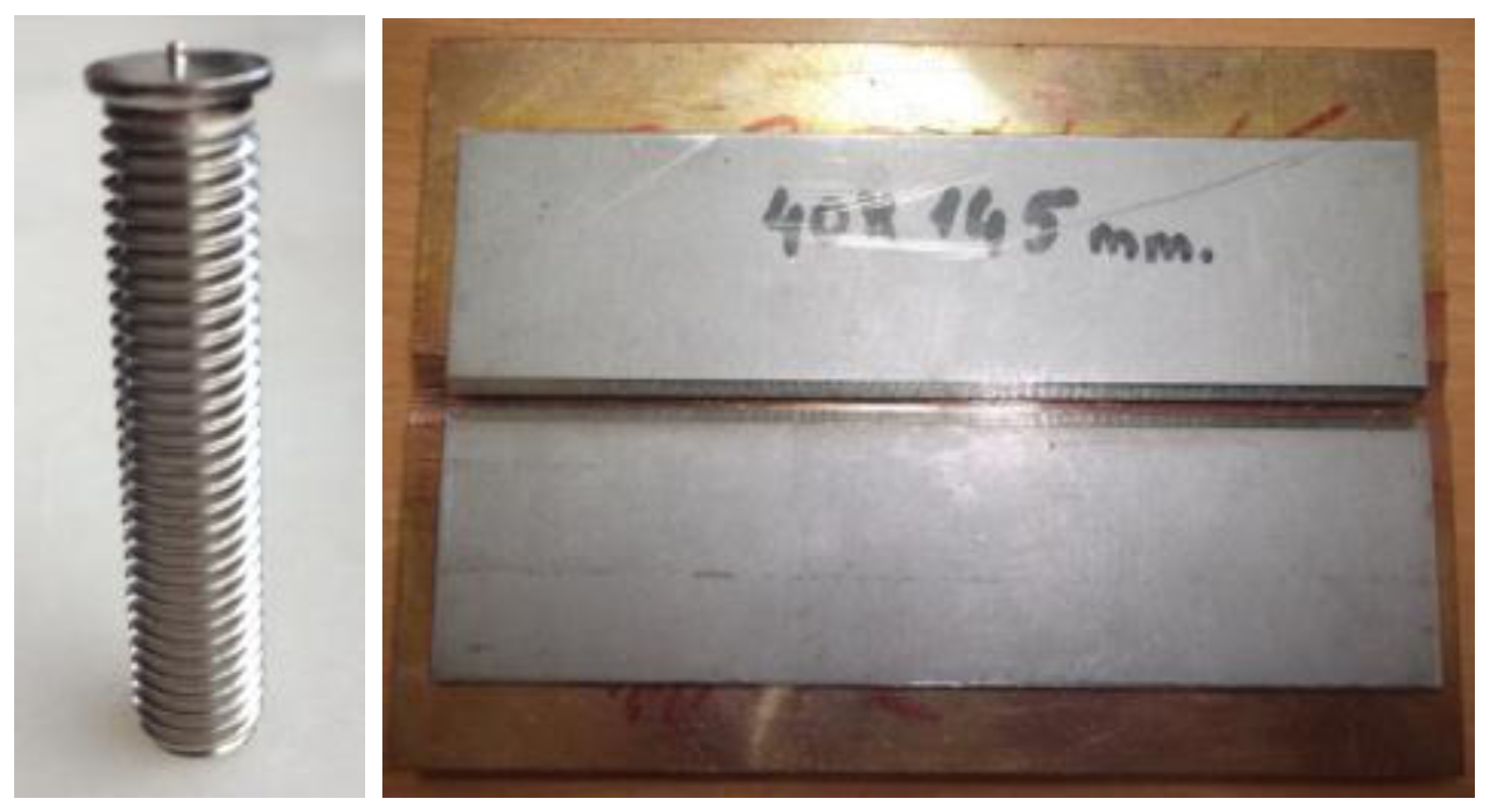
2. Materials and Methods
3. Results
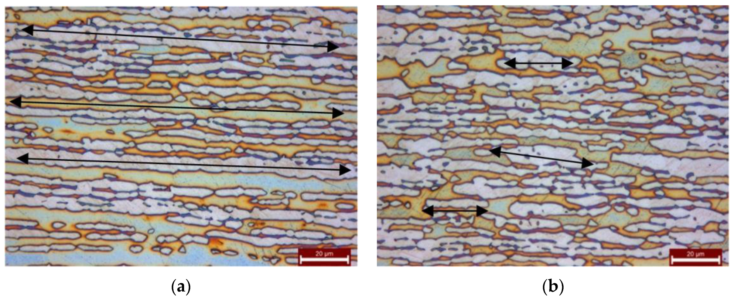
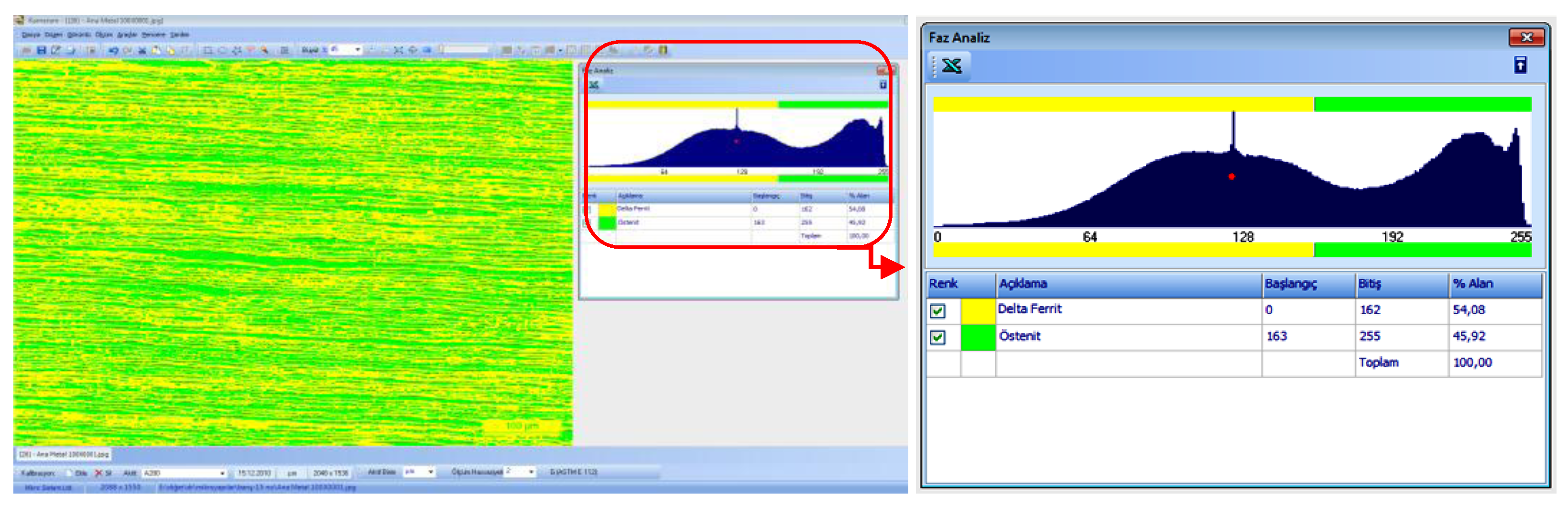
3.1. Microstructural Survey of Unwelded (Raw) Duplex Plates and Austenitic Studs
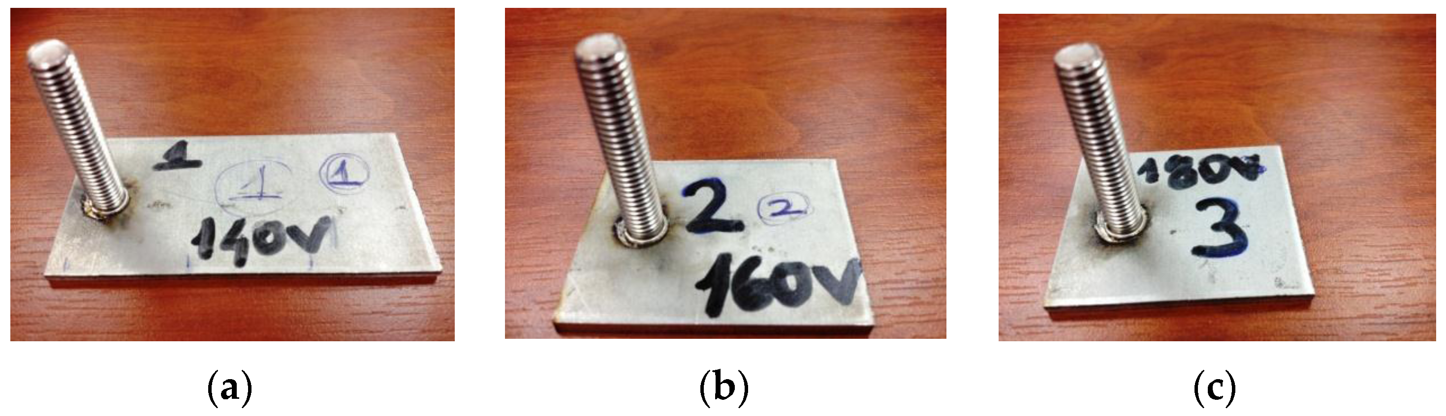
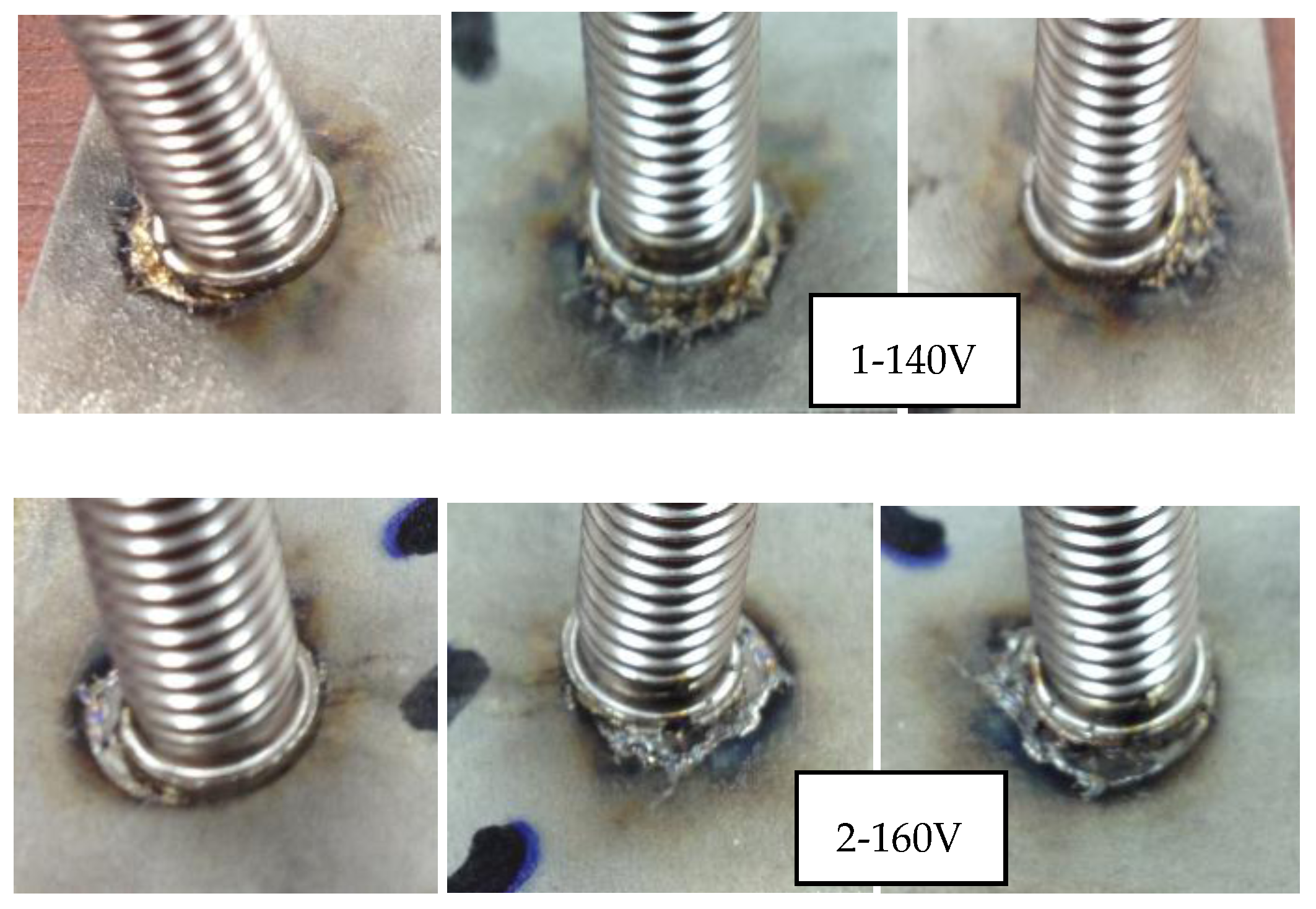
3.2. Visual Inspection of Arc Stud Welded Duplex Plates and Austenitic Studs
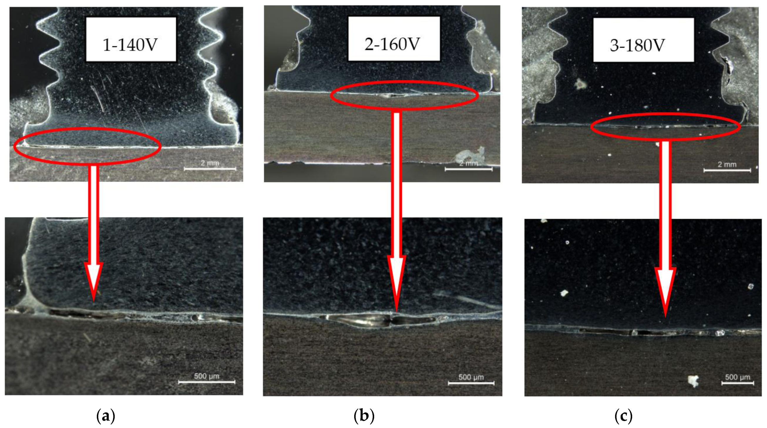
3.3. Macro-Structural Inspection of Weldments
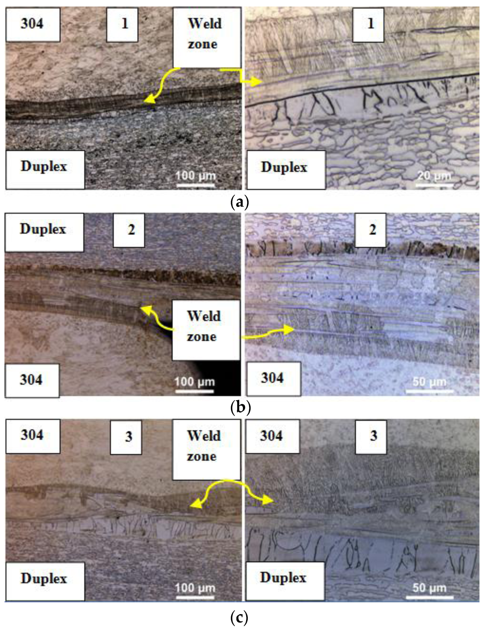
3.4. Micro-Structural Inspection of Weldments
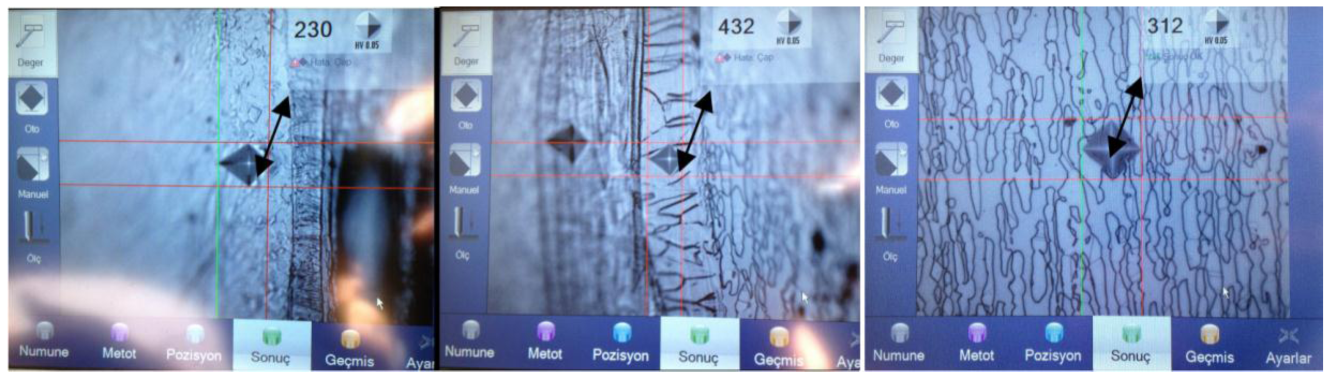
3.5. Microhardness Testing
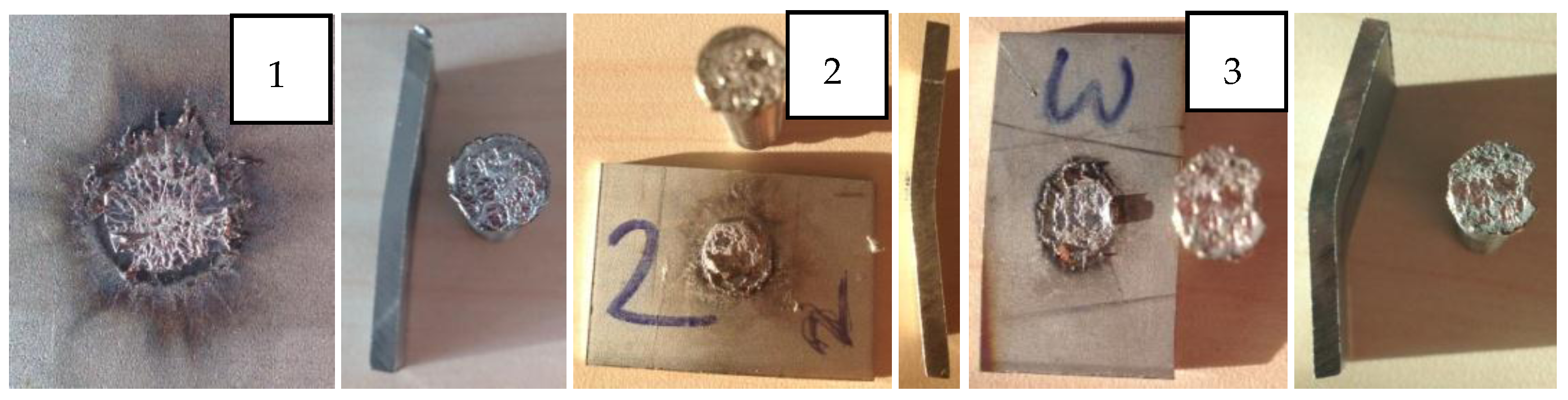
3.6. Tensile and Bend Testing of Weldments
3.7. Radiographic Inspection of Weldments
4. Discussion
5. Conclusions
Acknowledgments
Author Contributions
Conflicts of Interest
References
- Lippold, J.C.; Kotecki, D.J. Welding Metallurgy and Weldability of Stainless Steels; John Wiley and Sons Inc.: Hoboken, NJ, USA, 2005; pp. 250–251. [Google Scholar]
- Gunn, R.N. Duplex Stainless Steels Microstructures Properties and Applications; Abington Publishing: Cambridge, UK, 2005; pp. 24–76. [Google Scholar]
- ASM Handbook Committee. ASM Metals Handbook Volume 6: Welding Brazing and Soldering; ASM International: Materials Park, OH, USA, 1993. [Google Scholar]
- ASM Handbook Committee. ASM Metals Handbook Volume 9: Metallography and Microstructures of Stainless Steels and Maraging Steels; George, F., Vander, V., Eds.; ASM International: Materials Park, OH, USA, 2004. [Google Scholar]
- ASM Handbook Committee. ASM Metals Handbook Volume 13A: Corrosion: Fundamentals, Testing, and Protection; Cramer, S.D., Covino, B.S., Eds.; ASM International: Materials Park, OH, USA, 2003. [Google Scholar]
- Roberge, P.R. Handbook of Corrosion Engineering, Chapter 8 Materials Selection; Mc-Graw Hill Publications: New York City, NY, USA, 2000; pp. 717–730. [Google Scholar]
- Kou, S. Welding Metallurgy; John Wiley and Sons Inc.: Hoboken, NJ, USA, 2003; p. 227. [Google Scholar]
- Palmer, T.A.; Elmer, J.W.; Babu, S.S. Observations of Ferrite/Austenite Transformations in the Heat Affected Zone of 2205 Duplex Stainless Steel Spot Welds Using Time Re-solved X-Ray Diffraction. Mater. Sci. Eng. 2004, 374, 307–321. [Google Scholar] [CrossRef]
- Tehovnik, F.; Arzensek, B.; Arh, B.; Skobir, D. Microstructure Evolution in SAF 2507 Super Duplex Stainless Steel. Mater. Technol. 2011, 45, 339–345. [Google Scholar]
- ASTM E562-11. In Standard Test Method for Determining Volume Fraction for Systematic Manual Point Count; ASTM International: West Conshohocken, PA, USA, 2011.
- ASTM E1245-03. In Standard Practice for Determining the Inclusion or Second phase Constituent of Metals by Automatic Image Analysis; ASTM International: West Conshohocken, PA, USA, 2008.
- ASTM E112-13. In Standard Test Methods for Determining Average Grain Size; ASTM International: West Conshohocken, PA, USA, 2013.
- TS EN ISO 17655. In Destructive Tests on Welds in Metallic Materials—Method for Taking Samples for Delta Ferrite Measurement; ISO: Geneva, Switzerland, 2004.
- TS EN ISO 8249. In Welding-Determination of Ferrite Number (FN) in Austenitic and Duplex Stainless Steel Weld Materials; ISO: Geneva, Switzerland, 2000.
- ISO 14555. In Welding-Arc Stud Welding of Metallic Materials, 2nd ed.; ISO: Geneva, Switzerland, 2006.
- Zhang, W.; Debroy, T.; Palmer, T.A.; Elmer, J.W. Modeling of Ferrite Formation in a Duplex Stainless Steel Weld Considering Non-uniform Starting Microstructure. Acta Mater. 2005, 53, 4441–4453. [Google Scholar] [CrossRef]


| Material | C | Si | Mn | Cr | Ni | Mo | P | S | N | Fe | Others |
|---|---|---|---|---|---|---|---|---|---|---|---|
| Studs (304) | 0.038 | 0.290 | 1.570 | 18.90 | 10.83 | 0.297 | 0.022 | 0.0005 | 0.092 | 67.3 | 0.66 |
| Plates (S32205) | 0.016 | 0.340 | 0.832 | 24.95 | 6.638 | 3.511 | 0.015 | 0.0004 | 0.306 | 62.7 | 0.68 |
| Parameter | Arc Voltage (V) | Stud Lift (mm) |
|---|---|---|
| 1 | 140 | 7 |
| 2 | 160 | 7 |
| 3 | 180 | 7 |
| The Ferritetester—ISO 8249 and ANSI/AWS A4.2—Results by EN ISO 17655 Standard | Mean Value | Standard Deviation |
|---|---|---|
| 53.8 53.6 53.1 54.9 54.1 56.2 | 54 | 1.1125046816381 |
| Welded Sample | AISI 304 Studs | Heat Effected Zone Close to AISI 304 | Weld Metal (HV0.05) | Heat Effected Zone Close to S32205 | S32205 Plates | ||
|---|---|---|---|---|---|---|---|
| 140 V | 230 | 312 | 303 | 432 | 240 | 230 | 312 |
| 160 V | 230 | 317 | 312 | 371 | 312 | 303 | 312 |
| 180 V | 230 | 285 | 294 | 358 | 278 | 278 | 312 |
| Welded Sample | Tensile Strength 1 (N/mm2) | Tensile Strength 1 (N/mm2) Mean Values | Remarks | Bending Mean Value 2 (in degrees) | Remarks | |
|---|---|---|---|---|---|---|
| 1 | 2 | |||||
| 1 (140 V) | 360.65 | 237.158 | 298.904 | Fracture in weld zone, duplex plate is slightly bent by tensile test | 9 | Failed by bending tests |
| 2 (160 V) | 483.60 | 407.377 | 445.488 | Fracture in weld zone, duplex plate is bent by tensile test | 31 | Split and cracked by bending more than 31° Passed |
| 3 (180 V) | 443.169 | 442.076 | 442.6225 | Fracture in weld zone, duplex plate is extremely bent by tensile test | 57 | No split, no cracks up to 57° Passed |
© 2017 by the authors. Licensee MDPI, Basel, Switzerland. This article is an open access article distributed under the terms and conditions of the Creative Commons Attribution (CC BY) license ( http://creativecommons.org/licenses/by/4.0/).
Share and Cite
Başyiğit, A.B.; Kurt, A. Investigation of the Weld Properties of Dissimilar S32205 Duplex Stainless Steel with AISI 304 Steel Joints Produced by Arc Stud Welding. Metals 2017, 7, 77. https://doi.org/10.3390/met7030077
Başyiğit AB, Kurt A. Investigation of the Weld Properties of Dissimilar S32205 Duplex Stainless Steel with AISI 304 Steel Joints Produced by Arc Stud Welding. Metals. 2017; 7(3):77. https://doi.org/10.3390/met7030077
Chicago/Turabian StyleBaşyiğit, Aziz Barış, and Adem Kurt. 2017. "Investigation of the Weld Properties of Dissimilar S32205 Duplex Stainless Steel with AISI 304 Steel Joints Produced by Arc Stud Welding" Metals 7, no. 3: 77. https://doi.org/10.3390/met7030077