A Method Based on Semi-Solid Forming for Eliminating Coarse Dendrites and Shrinkage Porosity of H13 Tool Steel

1
Shenyang National Laboratory for Materials Science, Institute of Metal Research, Chinese Academy of Sciences, 72 Wenhua Road, Shenyang 110016, China
2
University of Chinese Academy of Sciences, 19 Yuquan Road, Beijing 100049, China
3
Key Laboratory of Nuclear Materials and Safety Assessment, Institute of Metal Research, Chinese Academy of Sciences, 72 Wenhua Road, Shenyang 110016, China
*
Author to whom correspondence should be addressed.
Metals 2018, 8(4), 277; https://doi.org/10.3390/met8040277
Submission received: 6 April 2018
/
Revised: 13 April 2018
/
Accepted: 16 April 2018
/
Published: 18 April 2018
Abstract
:A method called forging solidifying metal (FSM), which is applied for eliminating coarse dendrites and shrinkage porosity defects of ferrous alloys was proposed based on semi-solid forming technology (SSF). To verify its feasibility, the effects of liquid fraction (FL) on the microstructure of the deformed H13 steel were investigated experimentally. The coarse dendrites structure still existed and cracks appeared when the 0.1/s 50% FSM method was carried out at ~20% FL. What is significantly different from that is, the elimination of the coarse dendrites structure and shrinkage porosity defects became more significant, when this method was conducted at the end of solidification (FL < 10%). The microstructure of H13 steel was significantly refined and also became dense in such condition.
1. Introduction
Ferrous alloys are widely employed in industrial components such as dies and tools (H13, M2), metallurgical rollers (9Cr2MoV), etc. Excellent mechanical properties, such as high strength, hardness, and toughness, are the basic performance evaluation criteria for these materials. This combination of mechanical properties is achieved by a dense microstructure with fine grain [1]. From the perspective of ferrous alloy ingots, which regularly have a coarse dendritic structure and obvious porosity defects, grain refinement and the elimination of porosity are necessary to improve its microstructure and mechanical properties. In a conventional manufacturing route, the refinement of the grains is achieved by hot forging or the rolling process [2] as well as a subsequent heat treatment [3]. As it is difficult to obtain grain refinement only by single-pass deformation, a multipass forging or rolling process has been employed in the past [4]. In addition, a long homogenization time before the large deformation is required to reduce segregations, especially in the case of medium or high-alloyed steels. Porosity can be classified into micro-porosity and macro-porosity (also called shrinkage or void) based on its size [5]. Several researchers have attempted to find solutions for eliminating this primary metallurgical defect. For example, Wang et al. [6], Xu et al. [7], and Qian et al. [8] proposed that increasing the size of the hot top can help reduce porosity defects in heavy ingots via numerical simulation method. Lee et al. [9] described the closure of void during open die forging process. The results showed that a local effective strain value of 0.6 or larger must be achieved in order to eliminate the void during deformation. Xu et al. [10] and Li et al. [11] investigated the closing behavior of porosity during hot forging process and put forward the wide-anvil radial forging (WRF) method for its elimination in steel ingot. These traditional methods such as multipass high-compression ratio deformation, designing large-size hot tops and post-forging heat treatments, while being effective for eliminating the coarse dendritic structure and porosity defects, has disadvantages such as high-cost, low efficiency, and low material utilization. Therefore, a more efficient process for grain refinement and elimination of porosity defects in the steel ingot is highly desirable.
It is worth mentioning that since most ferrous alloys are solidified in dendrite mode, two types of defects mentioned above are formed during solidification [12]. Since the 1970s, with the raise and development of semi-solid forming technology (SSF), the solidification mode has changed. During the solidification process, mechanical agitation, electromagnetic stirring, etc., were used in the liquid-solid two phase region of metal, which could break the bulk dendrites structure and obtain spherical solid particle surrounded by liquid, thus realizing the refinement of the microstructure [13,14]. Flemings [12] also proposed that less casting shrinkage and fewer porosities can be obtained via SSF. The previous studies suggest that SSF can potentially replace the complex conventional route for eliminating the coarse dendritic structure and porosity defects in steel ingot. So far, several treatment methods in SSF have been proposed, including strain-induced melt activation (SIMA) [15], recrystallization and partial melting (RAP) [16], electromagnetic stirring [17], and the cooling slope process [18], etc. Due to the high forming temperatures of ferrous alloys, the forming tools which were in direct contact with the molten metal are prone to degrade during service [19]. Moreover, the transportation of the molten billets, also the oxidation of billets and precise temperature control during forming procedure were the bottlenecks in the application of SSF on high-melting ferrous alloys. Therefore, most of these methods are mainly used to produce low-melting alloys such as aluminum and magnesium. There has only been limited research on the application of the SSF in ferrous alloys [20].
In order to establish a more effective way than the conventional route for the production of ferrous alloy, the forging solidifying metal (FSM) method was proposed based on SSF in our previous study [21]. Unlike the traditional SSF, this method combined the solidification with large deformation process (LDP) in the two phase region. In the current study, to verify its effectiveness in eliminating coarse dendrites and porosity defects of ferrous alloys, the effects of liquid fraction (FL) on the microstructure of widely used H13 tool steel were investigated through a series of semi-solid compression tests.
2. Experimental Procedures
2.1. Material
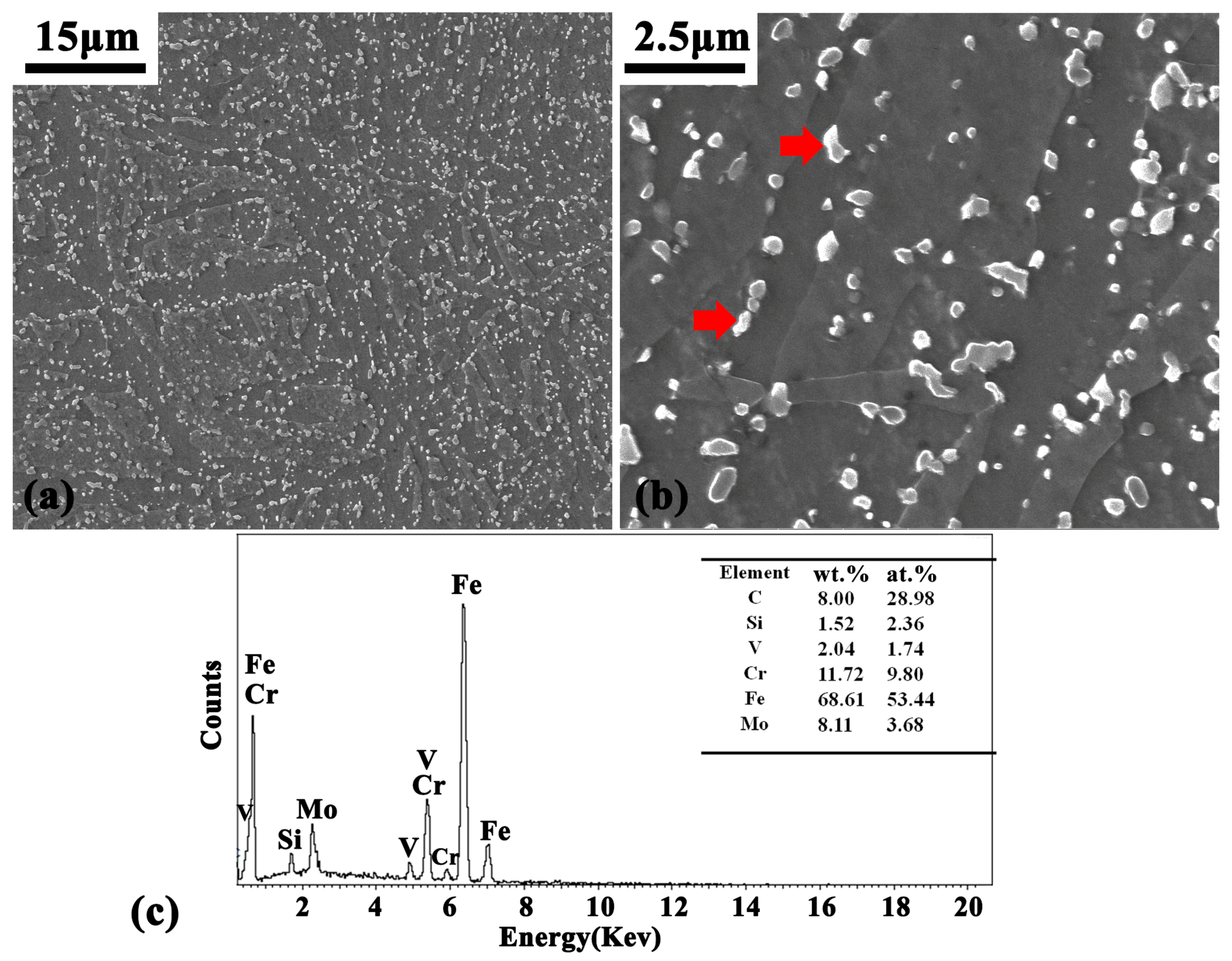
H13 steel is a commonly utilized material for components in die and tool applications. Coarse dendritic structure and porosity defects are the main problems during its manufacture. The chemical composition (in mass percentage) of H13 used in this study is shown in Table 1. The raw material was from a commercial using die (not served before), obtained by a series of complex procedures (casting, long-time homogenization treatment, multipass forging, post-forging heat treatment, etc.). The microstructure was characterized by martensite matrix and uniformly distributed precipitates (MXC type carbides), as shown in Figure 1. Most of the MXC type carbides precipitated during heat treatment after forging process [22].
2.2. Experiment Setup and Process Program
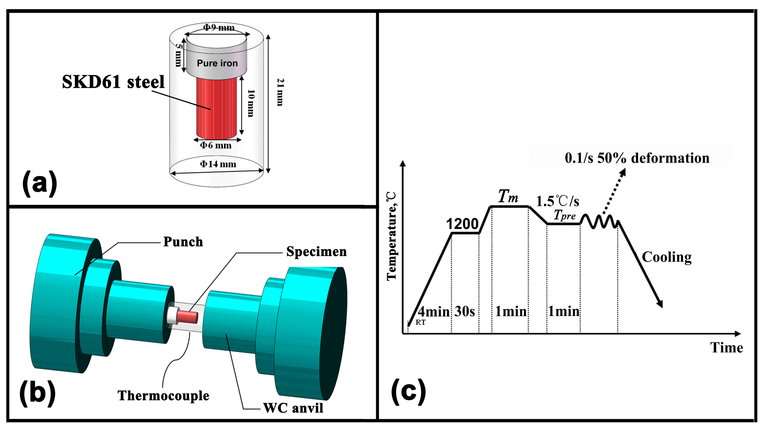
The semi-solid compression tests were conducted by thermal-simulator system (Gleeble 3800) from DSI Corporation (Albany, NY, USA). The sample design method in the tests was the same with that in our previous report [23]. Cylindrical specimens with diameter of 6 mm and height of 10 mm machined from the raw material were used. The cylindrical samples were put in pure iron hollow cylinders, which has an outer diameter of 14 mm and inner diameter of 6 mm. The H13 cylindrical samples were attached to the pure iron hollow cylinder by mechanical fit. Moreover, small pure iron cylinders with diameter of 9 mm and height of 5 mm were “stair-step” welded upon the hollow cylinder to avoid the leakage of molten H13 steel during the LDP, as shown in Figure 2a. The temperature and sample length were recorded by computer data acquisition system and the rate was 40 Hz. Temperatures were measured by a Type-R thermocouple welded to the midpoint of the samples and sample resistance heating currents were modulated to maintain predetermined temperatures (Tpre). During the semi-solid deformation, lubricated tantalum with graphite plate was placed between the specimen and tungsten carbide (WC) anvils, which was employed to ensure the uniform deformation of the specimens. The specimen was fixed inside the equipment and concentric with the WC dies. Vacuum pump system was used to avoid the oxidation of the specimen during the LDP in the two phase region (10−3 Torr), as shown in Figure 2b.
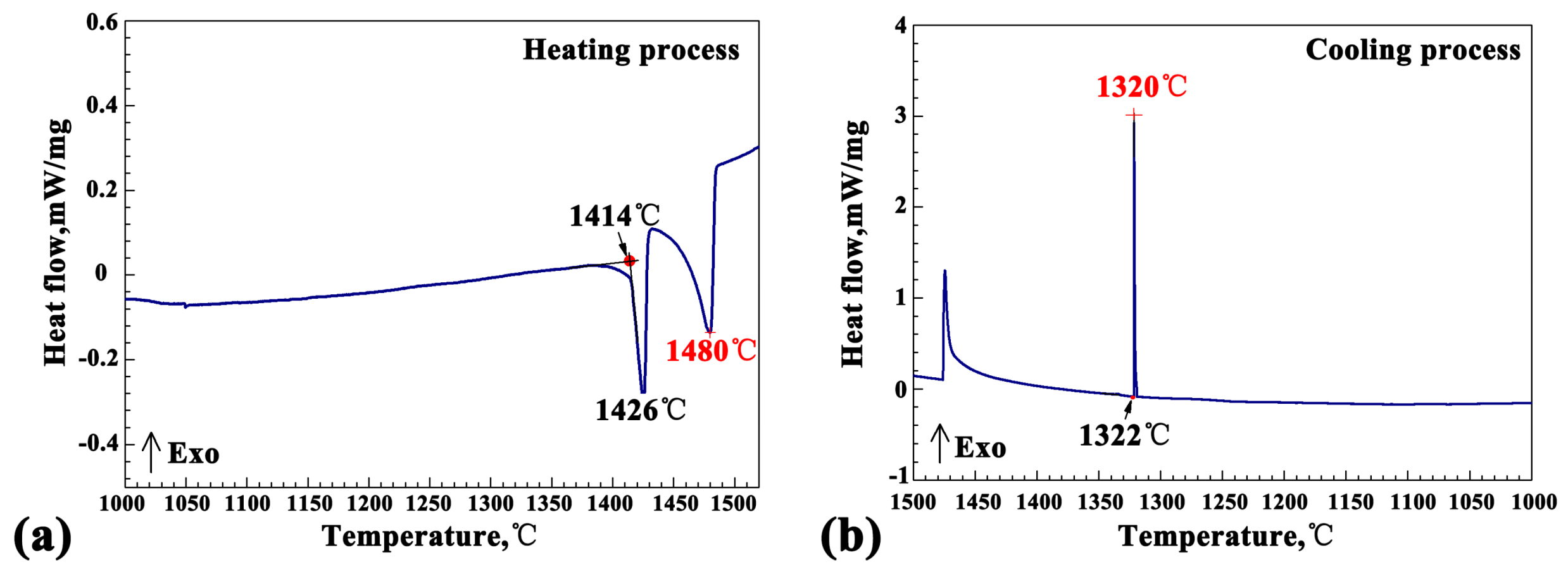
The solidification range of H13 steel was determined by Differential Scanning Calorimeter (DSC) experiment using as-received H13 steel by SETSYS Evolution18 thermal analyzer from SETARAM Corporation (Ratingen, Germany), and the heating and cooling rate was 5 °C/min during the experiment. The liquidus and solidus temperature were determined to be 1480 °C and 1320 °C, respectively, as shown in Figure 3 (red fonts). This result was in good agreement with Meng et al. [4]’s study, which reveals the microstructural evolution and deformation behavior of semi-solid H13 steel.
The process program of Gleeble 3800 was illustrated in Figure 2c. Specimens were heated to Tm (1480 °C) and hold 1 min to ensure that H13 steel was totally remelted in the center of the pure iron set. The pure iron cover outside was unchanged due to its higher melting point (about 1530 °C). Then specimens were cooled down to Tpre with a cooling rate of 1.5 °C/s and held isothermally for 1 min before the LDP implemented. Afterwards, the specimens were compressed to induce reduction of 50% at the strain rate of 0.1/s under an isothermal condition and then cooled in the instrument. The Tpre were 1420, 1400, 1380, 1360, 1340, 1320 °C, respectively. In contrast, the specimen (as-cast state) was heated to 1480 °C (hold 1 min) and then cooled at the rate of 1.5 °C/s to 1320 °C (solidus temperature). Afterwards the as-cast specimen was cooled down in the instrument to room temperature. Meng et al. [4] illustrated the FL versus Tpre relationship for H13 steel via RAP experiment using scandium image analysis software. According to their study, the FL versus Tpre relationship in this study are shown in Table 2. Notably, H13 steel was in solid state at 1320 °C but transformed into semi-solid state at higher temperatures. Hence, in order to elucidate the differences of microstructure as the FL varies, a series of semi-solid compression tests under different FL had been conducted.
2.3. Microstructural Characterization
After the LDP in the two phase region, the specimens were cut along the longitudinal-section. Standard metallographic procedures were used to mount, grind, and polish the specimens for macrostructure and microstructure analysis. Metallographic samples were chemically etched in 5% nitric acid/alcohol solution for 10 s. The microstructures of the specimens were observed using MC63 optical microscope (ZEISS Corporation, Jena, Germany) (as-chemical etched condition). The elements distribution on the specimens were observed through mapping analysis (as-polished condition), using electron probe micro-analyzer (EPMA-1610 made by SHIMADZU Company, Kyoto, Japan). The microstructure of the raw material was observed by INSPECT F50 SEM (FEI Corporation, Amsterdam, Netherlands). Carbides in raw material were identified by energy dispersive spectrometer (EDS) (Oxford Instruments, Oxford, UK) analysis in SEM.
3. Experimental Results
3.1. Macrostructural Inspection
Microstructures of the specimens (in longitudinal-section) under different experimental conditions are shown in Figure 4. The red arrows indicate the deformation direction during the semi-solid compression test (Figure 4a).
The macrostructure in the as-cast state showed obvious shrinkage defects (Figure 4b). However, the deformed specimens had a relatively dense macrostructure without shrinkage defects, as illustrated in Figure 4c–h. When deformed at higher temperature (1420 °C, 1400 °C and 1380 °C), the configuration of deformed H13 steel in the pure iron showed uneven deformation and “double-ear” morphology (Figure 4c–e). However, when deformed at lower temperature (1360 °C, 1340 °C and 1320 °C), the H13 steel showed a more uniform deformation (Figure 4f–h). In the case of the higher deformation temperatures, the FL of the semi-solid H13 billet inside the pure iron was higher, which corresponded to a stronger fluidity under external shear force. Therefore, the molten H13 metal flowed more easily into the gap between the pure iron set and its cover during the LDP, resulting in a double-eared appearance.
3.2. Microstructural Analyses
Figure 5 shows the microstructure of the specimens under different experimental conditions in the study. The microstructure of H13 (as-cast state) was dominated by bulky dendrites structure, which had obvious shrinkage and micro-porosity defects within it, as shown in Figure 5a. After the LDP in the two phase region, the selected microstructures of H13 steel in the specimens deformed at different temperature and FL are shown in Figure 5b–h. When deformed at higher FL (1400 °C and 1380 °C, corresponding to a FL of 20% and 18%, respectively), the coarse dendrites structure still existed and the crack defect appeared in the microstructure, as shown in Figure 5b,c. In comparison, when deformed at a lower FL (1360 °C and 1340 °C, corresponding a FL of 10% and 4%), the bulky dendrites structure disappeared. Compared with as-cast state, the microstructures under these conditions were refined, exhibiting large amounts of globular crystal or grains, as shown in Figure 5e–h. The globular crystal were surrounded by some “circle-like” structures when deformed at 10% FL (Figure 5f). Also, some “island-like” structures existed at the grain boundaries or within the grains when deformed at 4% FL, as shown in Figure 5h. In addition, the deformed H13 steel under these conditions had a dense microstructure without porosity defects. When deformed at completely solidified condition (1320 °C), the microstructure was mainly characterized by deformed banded dendrite structure. The obvious shrinkage defects in as-cast state were eliminated under such condition and some micro-porosity defects still existed, as shown in Figure 5d.
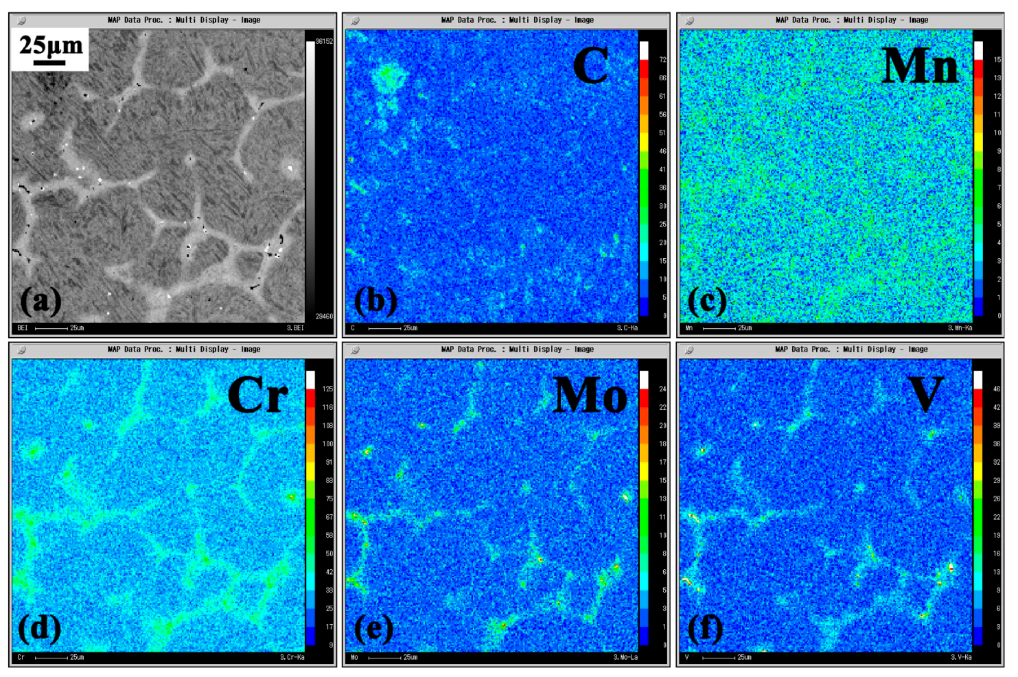
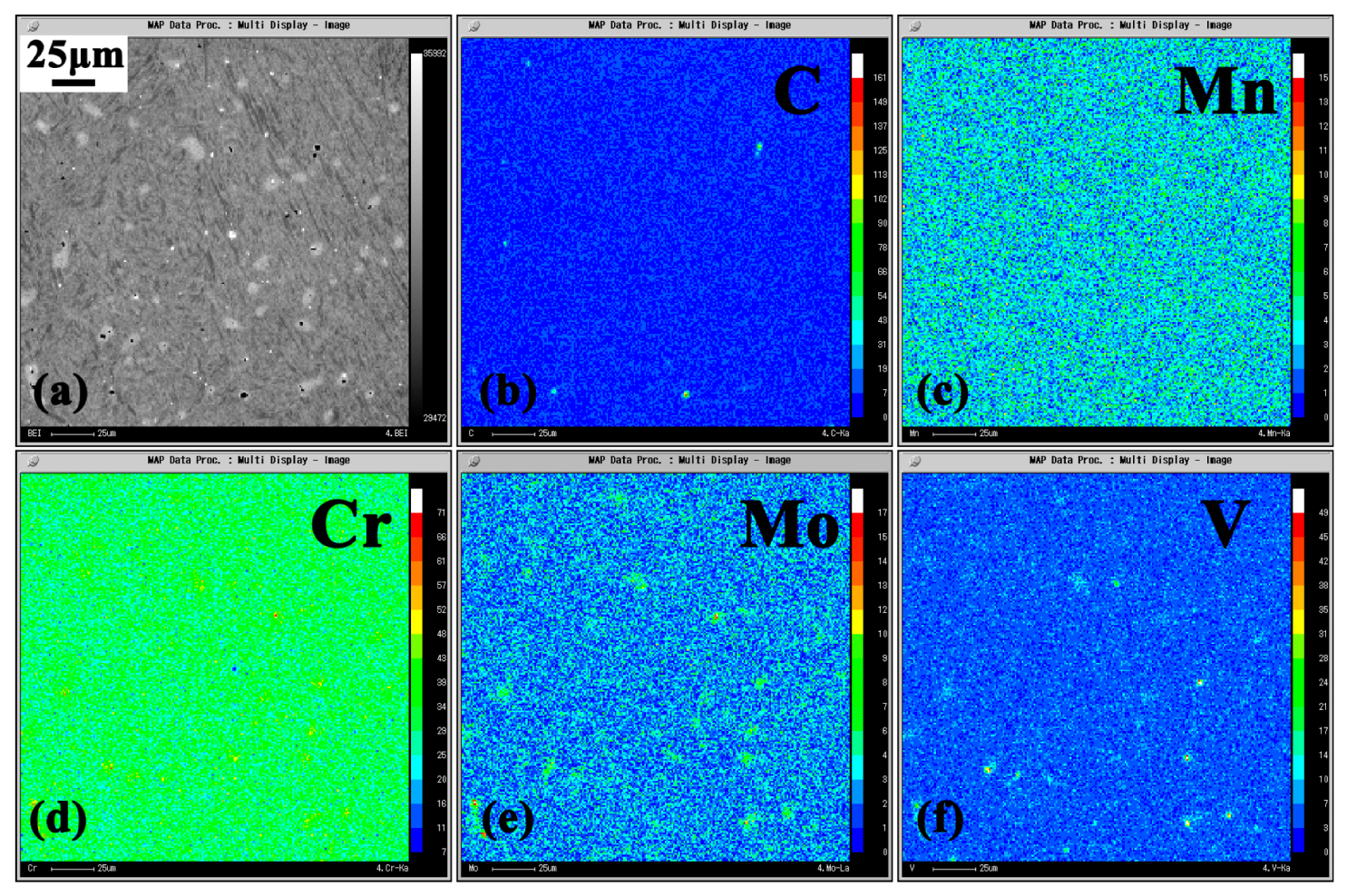
In order to characterize the “circle-like” and “island-like” structures in Figure 5f,h, the EPMA mapping analyses of main alloy elements of H13 steel (C, Mn, Cr, Mo, and V) was performed. From the results, both structures were rich in Cr, Mo, and V elements, as shown in Figure 6 and Figure 7.
To sum up, the elimination of the coarse dendrites structure and porosity defects of H13 steel became more significant, when the 0.1/s, 50% LDP in the two phase region (FSM method) was conducted at the end of solidification (with FL < 10%). The microstructure of H13 was significantly refined and also became dense. This result was promising as such microstructure may display better mechanical properties compared with the bulky microstructure of the as-cast ingot obtained by dendrite solidification, as shown in Figure 5a,e.
4. Discussion
4.1. Improvement of the Macrostructure
After the LDP in the two phase region, the obvious shrinkage in the as-cast state was eliminated in the deformed H13 specimens, under all conditions (Figure 5). In a previous study of the SSF process in H13 steel, Meng et al. [4] used a self-made test machine to reveal the basic semi-solid deformation characteristics of this alloy. A few macrocracks and severe oxidation appeared on the samples when deformed under higher FL conditions. While after the LDP in this study, no macrocracks nor severe oxidation were observed on these samples. The possible explanation for this is that, the H13 steel was deformed under a three-dimensional compressive stress state inside the pure iron shell in the current study, thus preventing the macrocrack formation during deformation. Moreover, the H13 steel was deformed and cooled within the pure iron shell in a vacuum atmosphere (Gleeble 3800), which cut off the air outside, and prevent the oxidation. To some extent, the FSM method overcomes the problem of oxidation of the billet (Ferrous alloy) in the traditional SSF.
4.2. Effects of LDP on Dendrite Structure
According to the recorded curve in Figure 3, the solidification interval of H13 steel is 160 °C, which is reasonably wide, making dendritic structure of such alloy well developed during dendrite solidification [24], as shown in Figure 5a. The experimental results indicated that, the addition of the LDP in the two phase zone had changed the dendrite solidification behavior of the H13 steel. However, the microstructures obtained significantly changed when deformed at different FL, as shown in Figure 5b–h. The mechanism was correlated with the different deformation behaviors under different FL conditions.
Flemings [12] proposed that the deformation mechanism in the solid-liquid two phase region changes with the FL. When deformed at a very high FL, as the dendrites structure was rare, few dendrites tended to rotate in the liquid melt during deformation. With decreasing in FL (~20%), more dendritic structures formed. The deformation mechanism changed from rotating to sliding because of the weak cohesion of the liquid film existed between the primary dendrites. When the FL of the alloy was very low (~10%), the dendritic structure in the melt was more and overlapped into a network skeleton. Under such condition, the mechanism of the deformation was dominated by the plastic deformation of the primary dendrites skeleton. The different deformation mechanisms result in different refinement effects of the dendritic structure of H13 steel in the study.
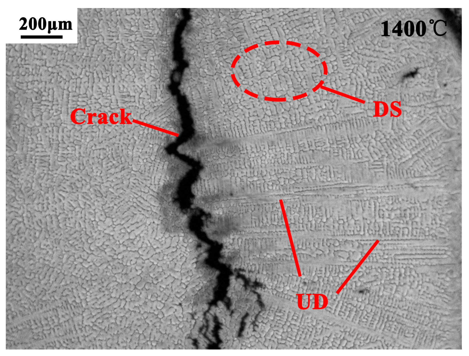
When deformed at 1420 °C, 1400 °C, and 1380 °C, where a higher LF of ~22%, ~20%, and ~18% existed in these samples, the sliding deformation mechanism played a dominant role. The primary dendrites in the melt were partially broken during the deformation and even some dendrites still remained unbroken (UD). Meanwhile, the deformation caused the remaining melt to generate forced convection and continuously wash out the primary columnar dendrites. The force convection may have caused the breakage or separation of dendrites, as illustrated by Campanella et al. [25] in their research on dendrite fragmentation criterion. As a result, a part of primary dendrites were broken into dendrite fragments to form the small dendrite structure (DS), as shown in Figure 8. Under such condition, the strength of the liquid films between the primary dendrites was lower than that of the dendritic matrix [26]. If the stress induced by solidification shrinkage, thermal contraction, or external deformation were large enough to overcome the strength of the liquid film, internal or open hot tears would result in these semi-solid regions [27]. Cai et al. [28] used the synchrotron tomographic quantification method to realize the in-situ observation of the hot tearing during the semi-solid compression (with ~25% FL) of Al–Cu alloy. Similarly, under such conditions, the hot tearing defects would also arise in the liquid film region due to the stress induced by 50% deformation in the study. The hot tearing would grow to the microcrack defect, as illustrated in Figure 8.
When deformed at the end of solidification (1360 °C and 1340 °C), the FL in the H13 sample was around or less than 10%. The dominant mechanism under such conditions was plastic deformation of the primary dendrites skeleton. The deformation in the mushy zone at a low FL (<10%) could lead to a complete transformation of the dendritic structure into numerous sub-grains, which had been reported by previous simulation [29] and experimental study [23]. As a result, the primary dendrite structure in this study was fully fragmented into large amounts of globular crystal or grains (Figure 5f,h). Before the deformation was implemented, the initial dendrites of H13 grew and the solute (Cr, Mo, and V) was ejected into the liquid (solute redistribution), resulting in its higher solute concentration in dendritic solidification. Therefore, the “circle-like” and “island-like” structures (Figure 5f,h) which were rich in solute elements were originated from the remaining melting after the semi-solid deformation, as shown in Figure 6 and Figure 7. Similar to the conventional SSF, a globular microstructure consists of spherical solid surrounded by high solute liquid was obtained when the LDP was carried out at 1360 °C (Figure 5e,f). As to 1340 °C, the remaining melting mainly distributed on the grain boundaries and a few existed within the grain. The remaining melting within the grain was from the entrapped liquid which was blocked within the solid phases during the semi-solid deformation. This phenomenon also appeared in other alloys during their semi-solid forming process [30,31,32]. The dendritic structures were eliminated and the microstructure was refined compared with as-cast state under these conditions.
4.3. Effects of LDP on Porosity
According to the formation mechanism, porosity can be divided into two main categories: gas-induced porosity and shrinkage-induced porosity [33]. Because of the sample design (pure iron cover) and experimental condition (vacuum atmosphere) in the study, the former (mostly originate from trapped air) is not taken into consideration. As to the shrinkage-induced porosity, volume shrinkage is coupled with solidification process of ferrous alloy due to an increase in the density with decreasing temperature [24]. This volume shrinkage can be compensated and eliminated by sufficient feeding at the early stage of solidification. However, this can be a problem as the solidification process continues, especially for alloys which have a wide solidification interval. In this study, the primary dendrites of H13 overlapped in a net-like structure at the end of the solidification with the remaining liquid within it. Due to the existence of these bulk dendrites structure, the liquid confined in the interdendritic regions, was unable to flow freely [34]. A series of studies [33,35,36] proposed that an inadequate interdendritic flow would lead to insufficient feeding and, to the formation of this type porosity in the interdendritic regions. Moreover, the size of these porosities would grow larger owing to the tensile stress during the volume shrinkage. Thus, it is clear that the formation of shrinkage-induced porosity occurs at the end of the solidification because of the insufficient feeding resulted from the bulk dendrites structure.
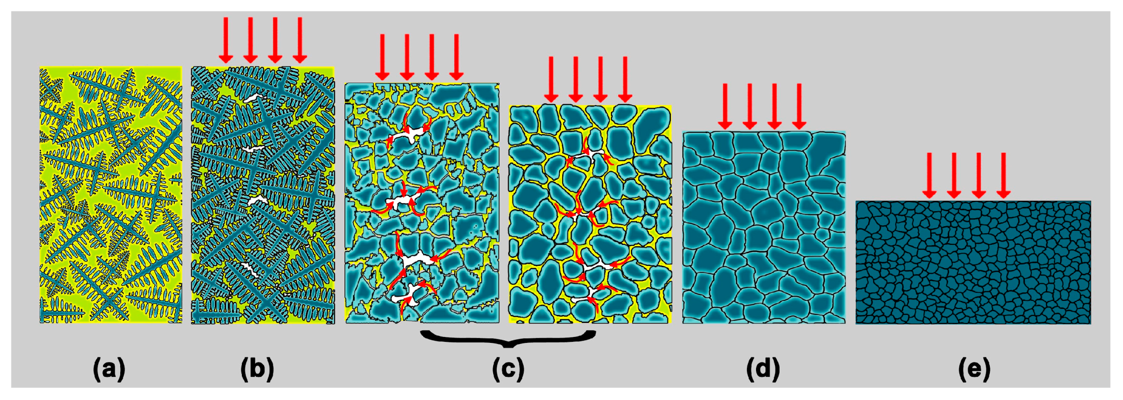
From the experimental results, the LDP at the end of the solidification had greatly eliminated the porosity defects of H13 steel, as shown in Figure 5f,h. On one hand, the bulk dendrites structures in the as-cast state were destroyed and fully transformed into large amounts of sub-grains under 50% two phase region deformation. Thus the residual liquid between the interdendritic regions was released and could flow freely, which was not conducive to the formation of the shrinkage porosity defects. On the other hand, the freely-flowing liquid between the sub-grains would play a role of forced feeding by the external deformation, which could also significantly eliminate the shrinkage porosity defects in their infancy. The mechanism is somewhat similar to the soft-reduction or heavy-reduction technology in continuous casting process. These methods also combine solidification under high pressure with forced feeding by plastic deformation to reduce the centerline porosity defects of continuous casting strands [5,37,38,39]. For both the reasons illustrated above, the shrinkage porosity defects of H13 steel were significantly eliminated and a dense microstructure was obtained (Figure 5f,h). To summarize, the mechanism in eliminating coarse dendrites structure and shrinkage porosity of SKD 61 steel under LDP in the two phase region in this study is illustrated in Figure 9.
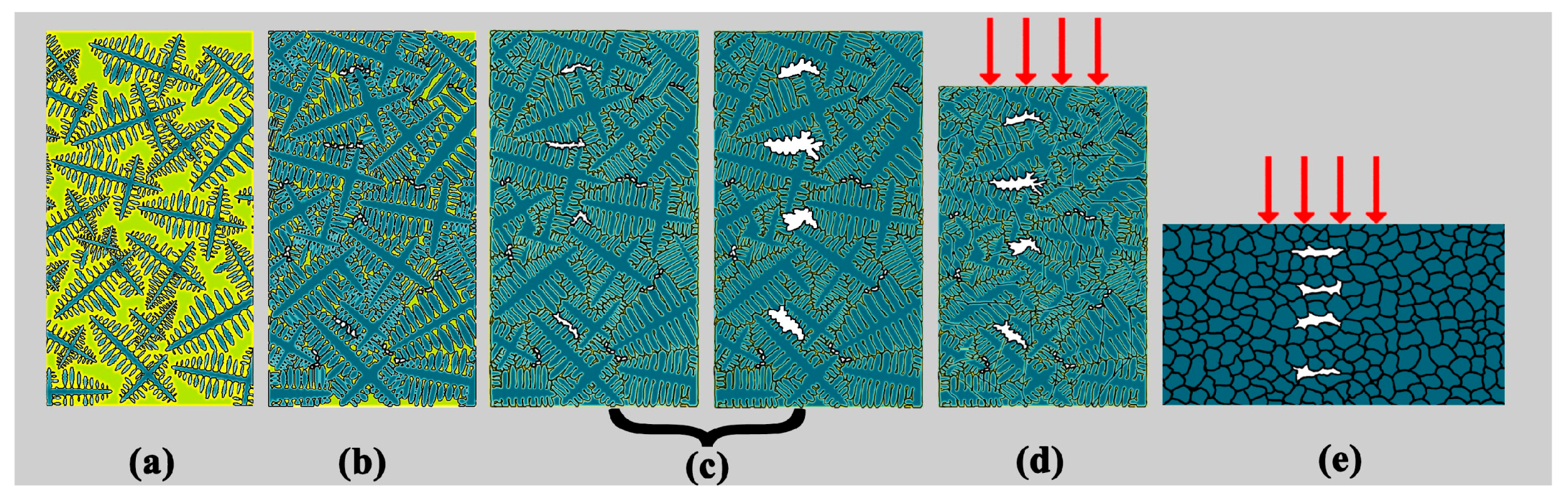
In comparison, the schematic evolution of shrinkage porosity defects when deformed after completely solidified condition (1320 °C) is illustrated in Figure 10 below. The shrinkage porosities defects formed in the end of the solidification (Figure 10b) would grow larger owing to the tensile stress during the volume shrinkage in the subsequent cooling process, as shown in Figure 10c. Once formed and grown, defects with larger dimensions were difficult to eliminate and transformed to micro-porosity after the complete solid deformation, as shown in Figure 5d and Figure 10e.
It should be noted that other than the two type defects investigated in the study, primary carbides and micro-segregation are also the main metallurgical defects in H13 steel. Further study is recommended to investigate the influence mechanism of LDP in the two phase region on both of these defects.
5. Conclusions
This study has demonstrated the potential of LDP in the two phase region (FSM method) to realize the efficient elimination of coarse dendrites and shrinkage porosity defects of H13 steel. The main results can be summarized as follows:
- The coarse dendrites of H13 steel were eliminated when LDP was carried out at the end of the solidification (0 < FL < 0.1) due to the plastic deformation mechanism under this condition.
- Because of the fragmentation of its primary dendrites structure and the forced feeding effect of the residual liquid due to external deformation, the shrinkage porosity defects of H13 steel were eliminated.
- The dense globular microstructure (H13 steel) consisted of spherical solid surrounded by high solute (Cr, Mo, and V) liquid was obtained when the 0.1/s 50% LDP was conducted at 1360 °C.
Acknowledgments
The authors acknowledge the financial support given by the National Key Research and Development Program (grant number 2016YFB0300401), National Natural Science Foundation of China (grant number U1508215), Key Program of the Chinese Academy of Sciences (grant number ZDRW-CN-2017-1), and the National Natural Science Foundation of China (grant number 51774265).
Author Contributions
Yifeng Guo and Weifeng Liu carried out the experiments and analyzed the results. Yifeng Guo and Mingyue Sun wrote and revised the manuscript. Bin Xu and Dianzhong Li contributed in the interpretation and discussion of results.
Conflicts of Interest
The authors declare no conflict of interest.
References
- Roberts, G.A.; Kennedy, R.; Krauss, G. Tool Steels; ASM International: Geauga County, OH, USA, 1998. [Google Scholar]
- Barani, A.A.; Li, F.; Romano, P.; Ponge, D.; Raabe, D. Design of high-strength steels by microalloying and thermomechanical treatment. Mater. Sci. Eng. A 2007, 463, 138–146. [Google Scholar] [CrossRef]
- Wei, S.; Lu, S. Effects of multiple normalizing processes on the microstructure and mechanical properties of low carbon steel weld metal with and without Nb. Mater. Des. 2012, 35, 43–54. [Google Scholar] [CrossRef]
- Meng, Y.; Sugiyama, S.; Yanagimoto, J. Microstructural evolution during RAP process and deformation behavior of semi-solid SKD61 tool steel. J. Mater. Process. Technol. 2012, 212, 1731–1741. [Google Scholar] [CrossRef]
- Dong, Q.; Zhang, J.; Wang, B.; Zhao, X. Shrinkage porosity and its alleviation by heavy reduction in continuously cast strand. J. Mater. Process. Technol. 2016, 238, 81–88. [Google Scholar] [CrossRef]
- Wang, J.; Fu, P.; Liu, H.; Li, D.; Li, Y. Shrinkage porosity criteria and optimized design of a 100-ton 30Cr2Ni4MoV forging ingot. Mater. Des. 2012, 35, 446–456. [Google Scholar] [CrossRef]
- Xu, Y.; Shen, H.; Lei, B.; Han, F. Simulation analysis on influence of riser height on quality of steel ingot. Spec. Cast. Nonferrous Alloys 2014, 34, 483–485. [Google Scholar]
- Qian, S.; Hu, X.; Cao, Y.; Kang, X.; Li, D. Hot top design and its influence on feeder channel segregates in 100-ton steel ingots. Mater. Des. 2015, 87, 205–214. [Google Scholar] [CrossRef]
- Lee, Y.S.; Lee, S.U.; Van Tyne, C.J.; Joo, B.D.; Moon, Y.H. Internal void closure during the forging of large cast ingots using a simulation approach. J. Mater. Process. Technol. 2011, 211, 1136–1145. [Google Scholar] [CrossRef]
- Xu, B. The void close behavior of large ingots during hot forging. Acta Metall. Sin. 2012, 48, 1194–1200. [Google Scholar] [CrossRef]
- Li, D. Design of forging methods of healing defects in ingots effectively. Acta Metall. Sin. 2016, 52, 1199–1206. [Google Scholar]
- Flemings, M.C. Behavior of metal alloys in the semisolid state. Metall. Trans. B 1991, 22, 269–293. [Google Scholar] [CrossRef]
- Kiuchi, M.; Kopp, R. Mushy/semi-solid metal forming technology—Present and Future. CIRP Ann.-Manuf. Technol. 2002, 51, 653–670. [Google Scholar] [CrossRef]
- Atkinson, H.V. Modelling the semisolid processing of metallic alloys. Prog. Mater. Sci. 2005, 50, 341–412. [Google Scholar] [CrossRef]
- Young, K.P.; Kyonka, C.P.; Courtois, J.A. Fine Grained Metal Composition. U.S. Patent 4,415,374, 15 November 1983. [Google Scholar]
- Kirkwood, D.H.T.U.; Sellars, C.M.T.; Elias, B.L.G.; Sheffield, U. Thixotropic Materials. U.S. Patent 5,133,811, 28 July 1992. [Google Scholar]
- Griffiths, W.D.; McCartney, D.G. The effect of electromagnetic stirring during solidification on the structure of Al-Si alloys. Mater. Sci. Eng. A 1996, 216, 47–60. [Google Scholar] [CrossRef]
- Mitsuru, A.; Hiroto, S.; Yasunori, H.; Tatsuo, S.; Satoru, S.; Atsushi, Y. Method and Apparatus for Shaping Semisolid Metals. U.S. Patent 6,851,466, 8 February 2005. [Google Scholar]
- Atkinson, H.V.; Rassili, A. A review of the semi-solid processing of steel. Int. J. Mater. Form. 2010, 3, 791–795. [Google Scholar] [CrossRef]
- Kirkwood, D.H.; Suéry, M.; Kapranos, P.; Atkinson, H.V.; Young, K.P. Semi-Solid Processing of Alloys; Springer: Berlin/Heidelberg, Germany, 2010. [Google Scholar]
- Guo, Y.; Cao, Y.; Sun, M.; Xu, B.; Li, D. Effects of liquid fraction on the microstructure and mechanical properties in forge solidifying 12Cr1MoV steel. J. Mater. Process. Technol. 2018, 256, 25–35. [Google Scholar] [CrossRef]
- Meng, Y.; Sugiyama, S.; Yanagimoto, J. Microstructural evolution during partial melting and semisolid forming behaviors of two hot-rolled Cr–V–Mo tool steels. J. Mater. Process. Technol. 2015, 225, 203–212. [Google Scholar] [CrossRef]
- Guo, Y.; Sun, M.; Xu, B.; Li, D. A method based on semi-solid forming for eliminating Laves eutectic phase of INCONEL 718 alloy. J. Mater. Process. Technol. 2017, 249, 202–211. [Google Scholar] [CrossRef]
- Davis, S.H. Theory of Solidification; Cambridge University Press: Cambridge, UK, 2001. [Google Scholar]
- Campanella, T.; Charbon, C.; Rappaz, M. Grain refinement induced by electromagnetic stirring: A dendrite fragmentation criterion. Metall. Mater. Trans. A 2004, 35, 3201–3210. [Google Scholar] [CrossRef]
- Atkinson, H.V. Semisolid processing of metallic materials. Met. Sci. J. 2011, 26, 1401–1413. [Google Scholar] [CrossRef]
- Flemings, M.C.; Martinez, R.A. Principles of microstructural formation in semi-solid metal processing. Solid State Phenom. 2014, 116–117, 1–8. [Google Scholar]
- Cai, B.; Karagadde, S.; Yuan, L.; Marrow, T.J.; Connolley, T.; Lee, P.D. In situ synchrotron tomographic quantification of granular and intragranular deformation during semi-solid compression of an equiaxed dendritic Al–Cu alloy. Acta Mater. 2014, 76, 371–380. [Google Scholar] [CrossRef]
- Yamaguchi, M.; Beckermann, C. Simulation of solid deformation during solidification: Shearing and compression of polycrystalline structures. Acta Mater. 2013, 61, 2268–2280. [Google Scholar] [CrossRef]
- Zhang, Y.F.; Liu, Y.B.; Zhang, Q.Q.; Cao, Z.Y.; Cui, X.P.; Wang, Y. Microstructural evolution of thixomolded AZ91D magnesium alloy with process parameters variation. Mater. Sci. Eng. A 2007, 444, 251–256. [Google Scholar] [CrossRef]
- Terzi, S.; Salvo, L.; Suéry, M.; Boller, E. In situ X-ray microtomography characterization of the entrapped liquid formed during partial remelting of a cold-rolled Al–8 wt % Cu alloy. Scr. Mater. 2009, 60, 671–674. [Google Scholar] [CrossRef]
- Li, L.; Zheng, M. Influence of time evolution of particle shape on rheological behavior of semisolid slurries of magnesium alloy AZ91D. Met. Mater. Int. 2016, 22, 252–259. [Google Scholar] [CrossRef]
- Riedler, M.; Michelic, S.; Bernhard, C. Formation of shrinkage porosity during solidification of steel: Numerical simulation and experimental validation. IOP Conf. Ser. Mater. Sci. Eng. 2016, 143, 012035. [Google Scholar] [CrossRef]
- Zhao, C.; Song, R. Evolution of microstructure and mechanical properties for 9Cr18 stainless steel during thixoforming. Mater. Des. 2014, 59, 502–508. [Google Scholar] [CrossRef]
- Pequet, C.; Rappaz, M.; Gremaud, M. Modeling of microporosity, macroporosity, and pipe-shrinkage formation during the solidification of alloys using a mushy-zone refinement method: Applications to aluminum alloys. Metall. Mater. Trans. A 2002, 33, 2095–2106. [Google Scholar] [CrossRef]
- Gupta, A.K.; Saxena, B.K.; Tiwari, S.N.; Malhotra, S.L. Pore formation in cast metals and alloys. J. Mater. Sci. 1992, 27, 853–862. [Google Scholar] [CrossRef]
- Li, G.; Yu, W.; Cai, Q. Investigation of reduction pretreatment process for continuous casting. J. Mater. Process. Technol. 2016, 227, 41–48. [Google Scholar] [CrossRef]
- Hiraki, S.; Yamanaka, A.; Shirai, Y.; Satou, Y.; Kumakura, S. Development of New Continuous Casting Technology (PCCS) for Very Thick Plate. Mater. Jpn. 2009, 48, 20–22. [Google Scholar] [CrossRef]
- Yim, C.H.; Won, Y.M.; Park, J.K.; Kwon, S.H. Continuous Cast Slab and Method for Manufacturing the Same. U.S. Patent 8,245,760, 21 August 2012. [Google Scholar]
Figure 1.
Original microstructure of H13 steel in this study, (a,b) images of the secondary electronic (SE) mode and (c) energy dispersive spectrometer (EDS) of scanning electron microscopy (SEM) analysis of the carbides (red arrows in (b)).
Figure 1.
Original microstructure of H13 steel in this study, (a,b) images of the secondary electronic (SE) mode and (c) energy dispersive spectrometer (EDS) of scanning electron microscopy (SEM) analysis of the carbides (red arrows in (b)).

Figure 2.
Schematic diagram of experiment setup in semi-solid compression tests (a,b) and process program (c). RT: room temperature; Tm: liquidus temperature; and Tpre: predetermined temperature.
Figure 2.
Schematic diagram of experiment setup in semi-solid compression tests (a,b) and process program (c). RT: room temperature; Tm: liquidus temperature; and Tpre: predetermined temperature.

Figure 3.
Differential scanning calorimeter (DSC) curve of H13 in this study (a) Heating process and (b) cooling process, respectively.
Figure 3.
Differential scanning calorimeter (DSC) curve of H13 in this study (a) Heating process and (b) cooling process, respectively.

Figure 4.
Macrostructures of the specimens (in longitudinal-section) under different experimental conditions in this study. (a) Schematic diagram of specimen, the red arrows are the deformation direction during the semi-solid compression tests; (b) as-cast state; (c–h) compressed specimens at different FL.

Figure 5.
Microstructures of the specimens under different experimental conditions in this study. (a) As-cast state; (b–h) compressed specimens at different FL; (f,h) are the local magnification of the microstructures in (e,g), respectively.
Figure 5.
Microstructures of the specimens under different experimental conditions in this study. (a) As-cast state; (b–h) compressed specimens at different FL; (f,h) are the local magnification of the microstructures in (e,g), respectively.

Figure 6.
Characterization of “circle-like” structures when deformed at 1360 °C. (a) Back scatter mode, (b–f) are C, Mn, Cr, Mo, and V elemental distributions, respectively.
Figure 6.
Characterization of “circle-like” structures when deformed at 1360 °C. (a) Back scatter mode, (b–f) are C, Mn, Cr, Mo, and V elemental distributions, respectively.

Figure 7.
Characterization of “island-like” structures when deformed at 1340 °C. (a) Back scatter mode, (b–f) are C, Mn, Cr, Mo, and V elemental distributions, respectively.
Figure 7.
Characterization of “island-like” structures when deformed at 1340 °C. (a) Back scatter mode, (b–f) are C, Mn, Cr, Mo, and V elemental distributions, respectively.

Figure 8.
Microstructure of H13 steel deformed at 1400 °C (50%, 0.1/s). UD: Unbroken dendrite. DS: Small dendrite structure.
Figure 8.
Microstructure of H13 steel deformed at 1400 °C (50%, 0.1/s). UD: Unbroken dendrite. DS: Small dendrite structure.

Figure 9.
Schematic diagram of mechanism in eliminating coarse dendrite structures and shrinkage porosity in the study (The white regions in b and c represent shrinkage porosity, the yellow regions in a, b, and c represent liquid). (a) The initial dendrites grew during the solidification and continued discharging solute elements (such as Cr, Mo, and V) to the melt; (b) at the end of solidification, the dendrites formed a cohesive network. The reason is due to the insufficient feeding in the interdendritic region, shrinkage porosity defects formed. In this case, the 0.1/s, 50% LDP was implemented; (c) Under the large strain induced by the large deformation, the primary dendrites were fully broken to large amounts of sub-grains with high-solute liquid surrounded (Figure 5e,f and Figure 6). The residual liquid between the interdendritic regions were released and could flow freely, which plays a role of forced feeding by the external deformation (red arrow in c). Due to these reasons, the coarse dendrites structure and shrinkage porosity defects were eliminated. The sub-grains gradually grew and spheroidized during the process; (d,e) the microstructure was refined due to recrystallization in the subsequent deformation.

Figure 10.
Schematic evolution of shrinkage porosity defects when deformed after completely solidified condition (1320 °C) in the study (The white regions in (b–e) represent shrinkage porosity, the yellow regions in (a–c) represent liquid).
Figure 10.
Schematic evolution of shrinkage porosity defects when deformed after completely solidified condition (1320 °C) in the study (The white regions in (b–e) represent shrinkage porosity, the yellow regions in (a–c) represent liquid).


Table 1.
Chemical composition of H13 steel (wt %).
| Element | C | Si | Mn | Cu | Ni | Cr | Mo | V | Fe |
|---|---|---|---|---|---|---|---|---|---|
| Analyzed | 0.36 | 0.94 | 0.45 | 0.09 | 0.05 | 5.16 | 1.2 | 0.88 | Bal. |
Table 2.
The corresponding liquid fraction (FL) versus Tpre relationship according to the Meng et al. study [4].
Table 2.
The corresponding liquid fraction (FL) versus Tpre relationship according to the Meng et al. study [4].
| Tpre (°C) | FL |
|---|---|
| 1420 | ~22% |
| 1400 | ~20% |
| 1380 | ~18% |
| 1360 | ~10% |
| 1340 | ~4% |
| 1320 | ~0% |
© 2018 by the authors. Licensee MDPI, Basel, Switzerland. This article is an open access article distributed under the terms and conditions of the Creative Commons Attribution (CC BY) license (http://creativecommons.org/licenses/by/4.0/).
Share and Cite
MDPI and ACS Style
Guo, Y.; Liu, W.; Sun, M.; Xu, B.; Li, D. A Method Based on Semi-Solid Forming for Eliminating Coarse Dendrites and Shrinkage Porosity of H13 Tool Steel. Metals 2018, 8, 277. https://doi.org/10.3390/met8040277
AMA Style
Guo Y, Liu W, Sun M, Xu B, Li D. A Method Based on Semi-Solid Forming for Eliminating Coarse Dendrites and Shrinkage Porosity of H13 Tool Steel. Metals. 2018; 8(4):277. https://doi.org/10.3390/met8040277
Chicago/Turabian StyleGuo, Yifeng, Weifeng Liu, Mingyue Sun, Bin Xu, and Dianzhong Li. 2018. "A Method Based on Semi-Solid Forming for Eliminating Coarse Dendrites and Shrinkage Porosity of H13 Tool Steel" Metals 8, no. 4: 277. https://doi.org/10.3390/met8040277
Note that from the first issue of 2016, this journal uses article numbers instead of page numbers. See further details here.