Article

A Numerical Study on Co-Extrusion to Produce Coaxial Aluminum-Steel Compounds with Longitudinal Weld Seams

by
Bernd-Arno Behrens
1,
Christian Klose
2,
Alexander Chugreev
1,
Norman Heimes
1,
Susanne Elisabeth Thürer
2 and
Johanna Uhe
1,*
1
Institut für Umformtechnik und Umformmaschinen (Forming Technology and Machines), Leibniz Universität Hannover, 30823 Garbsen, Germany
2
Institut für Werkstoffkunde (Materials Science), Leibniz Universität Hannover, 30823 Garbsen, Germany
*
Author to whom correspondence should be addressed.
Metals 2018, 8(9), 717; https://doi.org/10.3390/met8090717
Submission received: 30 July 2018 / Revised: 5 September 2018 / Accepted: 9 September 2018 / Published: 13 September 2018

Abstract

:
The use of lightweight materials is one possibility to limit the weight of vehicles and to reduce CO2 emissions. However, the mechanical properties and weight-saving potential of mono-materials are limited. Material compounds can overcome this challenge by combining the advantages of different materials in one component. Lateral angular co-extrusion (LACE) allows the production of coaxial semi-finished products consisting of aluminum and steel. In this study, a finite element model of the LACE process was built up and validated by experimental investigations. A high degree of agreement between the calculated and experimentally determined forces, temperatures, and the geometrical shape of the hybrid profiles was achieved. In order to determine suitable parameters for further extrusion experiments, the influence of different process parameters on material flow and extrusion force was investigated in a numerical parametric study. Both the temperature and extrusion ratio showed a significant influence on the occurring maximum extrusion force as well as the material flow inside the LACE tool. The maximum force of 2.5 MN of the employed extrusion press was not exceeded. An uneven material flow was observed in the welding chamber, leading to an asymmetric position of the steel rod in the aluminum matrix.

1. Introduction

The use of lightweight construction materials is one possibility to limit CO2 emissions [1]. Aluminum alloys (6xxx) are low-cost lightweight materials that can be strengthened by heat treatment and are easy to process by extrusion. Depending on the aluminum content, a material composite made from aluminum and steel is significantly lighter than mono-material steel parts. One possibility of combining aluminum and steel into hybrid semi-finished workpieces is co-extrusion.
Within the Collaborative Research Centre 1153, a lateral angular co-extrusion (LACE) process of aluminum and steel was developed where a coaxial position of the steel rod within the matrix material was realized [2]. This development was based on the process proposed by Grittner et al. and allowed the co-extrusion of the asymmetric compound profiles of aluminum and titanium using conventional aluminum billets. According to their study, the aluminum alloy was redirected at an angle of 90° within the tool and joint with the titanium profile in the welding chamber [3]. The coaxial aluminum-steel compounds considered in the present study, consisting of the case-hardening steel 20MnCr5 and the aluminum alloy EN AW-6082, are processed into hybrid bearing bushings by die forging in the further course of the process chain. Here, the case-hardening steel acts as the inner wear-resistant surface of the hybrid bearing bushing whereas the aluminum alloy allows for lower weight in areas not subjected to high mechanical loads or wear. Contrary to conventional process chains, the joining of the different materials takes place prior to the main forming process during Tailored Forming. Thus, the strength and quality of the joining zone are improved by means of the thermo-mechanical treatment during the forming and machining processes [4].
As an initial step in designing and further improving extrusion and co-extrusion processes, numerical modelling has become a common way to study the material flow and process variables under various conditions. Finite Element (FE) simulation can be used to make initial predictions about the process, reduce the costs of experimental tests, and save resources. The high number of experiments required for detailed analyses of co-extrusion processes can be significantly reduced through the use of computer modelling. In addition, the actual values of local parameters like temperature or contact pressure are often difficult to obtain and are sometimes not measurable during extrusion processes. There have been several studies using FE simulation to investigate the extrusion process of aluminum alloys [5,6,7,8] and different types of co-extrusion processes [9,10,11].
There are two different variants of co-extrusion processes [12]. On the one hand, conventional extrusion billets and a reinforcing element can be used, which are fed into the deformation zone from the outside. In this case, only the billet material is plastically deformed [13]. On the other hand, modified extrusion billets with reinforcing elements integrated in the billet matrix material or hybrid extrusion billets have also been used [9,14]. In this case, matrix material and reinforcement are formed.
Many numerical investigations on processes with thin reinforcing elements like steel wires or modified extrusion billets are available in the literature. For example, Pietzka et al. determined the minimum distance between the reinforcing elements in the composite extrusion of thin aluminum profiles with reinforcing elements with a diameter of 1.5 mm using FEM [15]. Kazanowski et al. investigated the influence of the initial billet geometry on the resulting product in bi-material extrusion [9]. The co-extrusion of hybrid magnesium–aluminum billets was investigated by Priel et al. [10]. In contrast to the LACE process, both materials are formed using these methods. Hence, usually no redirection of the matrix material is necessary for the processes described in the literature.
In the present study, an FE model of the LACE process was established and validated by experimental extrusion experiments which were performed at different ram speeds of 2 mm·s−1 and 4 mm·s−1. The metal flow into the welding chamber and die, the extrusion force-time curves, the temperature development of the steel rod as well as the resulting geometry of the profile were used to validate the FE model. For an accurate prediction of thermomechanical material behavior during the extrusion process, flow curves of both the aluminum alloy EN AW-6082 and the case hardening steel 20MnCr5, were experimentally determined by means of uniaxial cylindrical upsetting tests and implemented in the FE software. The influence of billet temperature and extrusion ratio on extrusion force and material flow were investigated numerically to define suitable process parameters for further extrusion experiments.

2. Materials and Methods

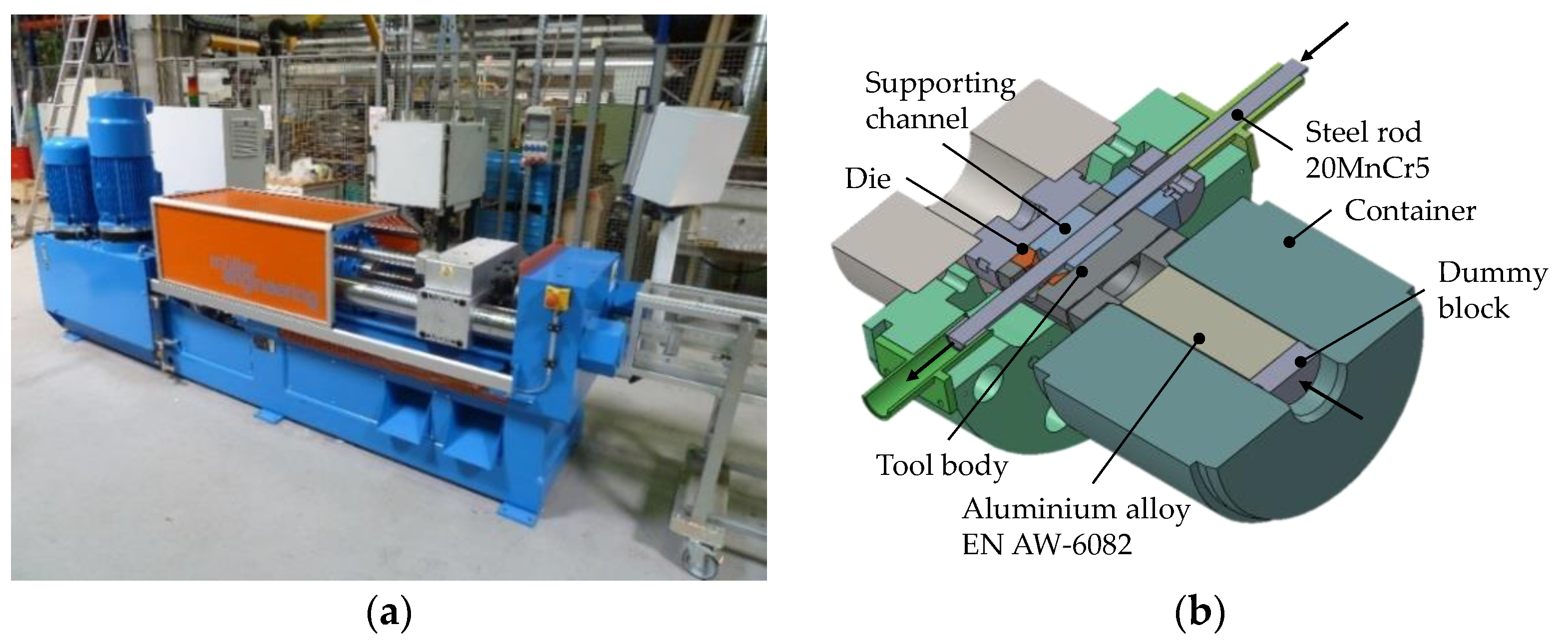
2.1. Experimental Procedure

The experiments described in this study were carried out on a 2.5 MN extrusion press (Müller engineering GmbH, Todtenweis, Germany) shown in Figure 1a. The LACE process investigated for the production of aluminum-steel compound profiles with a steel rod as a coaxial reinforcing element was developed by Thürer et al. [2]. The tool concept is presented in Figure 1b. During the process, aluminum was extruded at an angle of 90° between the punch direction and die to enable a continuous feed of the reinforcement into the welding chamber. 20MnCr5 steel rods were used as reinforcements for the described fundamental extrusion experiments on a laboratory scale. The friction between steel and aluminum caused the steel rod to move during the co-extrusion process. The initial dimensions of the aluminum billet and the steel rod are provided in Table 1. By using an aluminum billet with an initial diameter of 56 mm, a diameter of the steel rod of 15.2 mm, and an inner diameter of the die of 28 mm, an extrusion ratio of 6:1 was achieved. The die was lubricated with MoS2.
Prior to the experiments, the billets, the dummy block, and the die were preheated to 500 °C for 2 h in a conventional furnace while the temperature of the steel rod initially equaled room temperature. The temperature of the container was 490 °C. Ram speeds of 2 mm·s−1 and 4 mm·s−1 were chosen for the described co-extrusion experiments. During the experiments, the extrusion force-time curves were recorded. In order to validate the numerical results, the temperature of the steel rod was monitored using a thermocouple type K that was positioned at a distance of 350 mm from the tip of the steel rod. The thermocouple was fixed inside a hole that was drilled to the middle of the steel rod cross-section and routed in a groove on the surface of the steel rod.
To characterize the thermomechanical material behavior of the billet and the steel rod, flow curves of EN AW-6082 and 20MnCr5 were determined by means of standard cylindrical upsetting tests [16]. The upsetting tests were carried out on a servo hydraulic forming simulator (Instron GmbH, Darmstadt, Germany) at temperatures between 400 °C and 550 °C for aluminum and between room temperature and 600 °C for steel with constant strain rates of 1 s−1 and 10 s−1. The cylindrical specimens were wire-cut from cylindrical billets of continuously cast EN AW-6082 and 20MnCr5 to a diameter of 8 mm and a length of 12 mm. The dies consisted of Inconel 718 (2.4668). In order to guarantee isothermal conditions, the setup was supplemented with a thermal tank. The specimens and the thermal tank were heated up to forming temperature in a chamber furnace with a uniform holding time to ensure the complete heating of the samples and the thermal tank. Thermocouples were integrated in the thermal tank and the specimen. In order to ensure statistical coverage, at least three tests were carried out for each parameter combination.

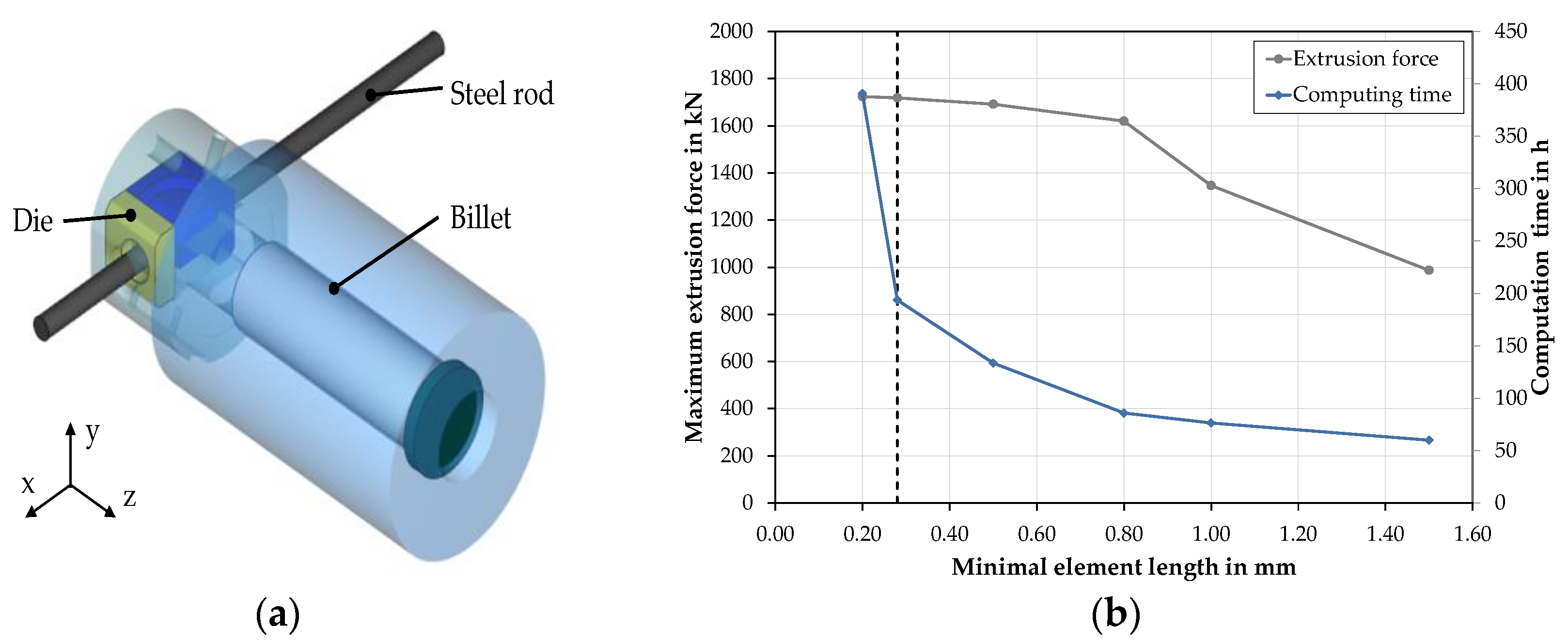
2.2. Numerical Model

The commercial FE software FORGE NxT 1.1 (Transvalor S. A., Mougins, France) was used to model and compute the developed co-extrusion process. The determined flow curves were implemented in the FE software as a function of strain, strain rate, and forming temperature to model the thermomechanical material behavior of the billet and the steel rod material. The time step value equaled 0.03 s, which resulted in 3300 time steps in total. The tools were modelled as rigid bodies to limit the computation time. For the simulation model, only the internal components that were in contact with the aluminum billet or the steel rod were considered. In order to prevent elements being pulled between the individual components, which would lead to large element distortions, the container and distance plate were joined together to form a single component. The 3D FE model is presented in Figure 2a and comprises approximately 158,000 volume elements (tetrahedrons) of a linear interpolation type typical for metal forming simulations. The Lagrangian approach was used to model the co-extrusion process. Due to intensive plastic deformation during the redirection and extrusion within the LACE process, remeshing was applied. In this case, two remeshing criteria, a periodic initiated remeshing criterion and an automatic size criterion were used. Due to this, remeshing followed a fixed incremental step of 20 steps. Additionally, the automatic size criterion was activated to refine the mesh of the workpiece according to the curvature of the die in the contact area.
In order to ensure that at least five elements were present along the thickness of the aluminum part in the area of the profile exit, a refinement box was employed. By means of the refinement box, the volume loss caused by coarse mesh and remeshing was reduced from 12 to 2%.
Preliminary investigations of the element size of the process have shown that both the accuracy of the calculated results and the computation time are strongly dependent on the selected minimal element size. Based on the results of this mesh study, the model with a minimum element edge length of 0.28 mm was used for the numerical investigations, since a sufficiently high accuracy and a reasonable computing time could be achieved (Figure 2b).
For the description of the frictional behavior between the billet and tools, the constant shear model (Tresca’s friction model) was used. According to the literature, friction factors between m = 0.7 and m = 1.0 are used to describe the frictional behavior in aluminum extrusion [17]. Simulations with friction factors between 0.7 and 1.0 were carried out and compared with the experimental results for an inverse determination of the friction value. The friction between the billet and die was defined with the help of the combined friction model. The friction coefficient µ was set to 0.15 whereas the friction factor m was assigned a value of 0.3 due to the lubrication of the die in the experimental investigations. The friction factor at the interface between the aluminum matrix material and steel rod was considered with a bilateral sticking condition as the steel rod only moved due to the friction between both materials in the experiments. For the heat transfer coefficient, a value of 35 kW·m−2·K−1 was chosen based on data from the literature [18]. The ambient temperature was set to 50 °C. In order to shorten computation time, the process symmetry available was exploited. Since no significant differences were found in the force time-curves, temperature, or velocity fields, a half model was used for the numerical parametric study. Consequently, computation time could be reduced by two thirds without impairing the quality of the results.
A numerical process design study was carried out to determine suitable process parameters for further experimental investigations. Therefore, the initial billet temperature and tool temperature varied between 420 °C and 540 °C, while the ram speed was set to 2 mm·s−1 or 4 mm·s−1, respectively. By using steel rods with varying diameters, the extrusion ratio varied between 6:1 and 9:1. The process parameters used for the numerical parametric study are given in Table 2.

3. Results

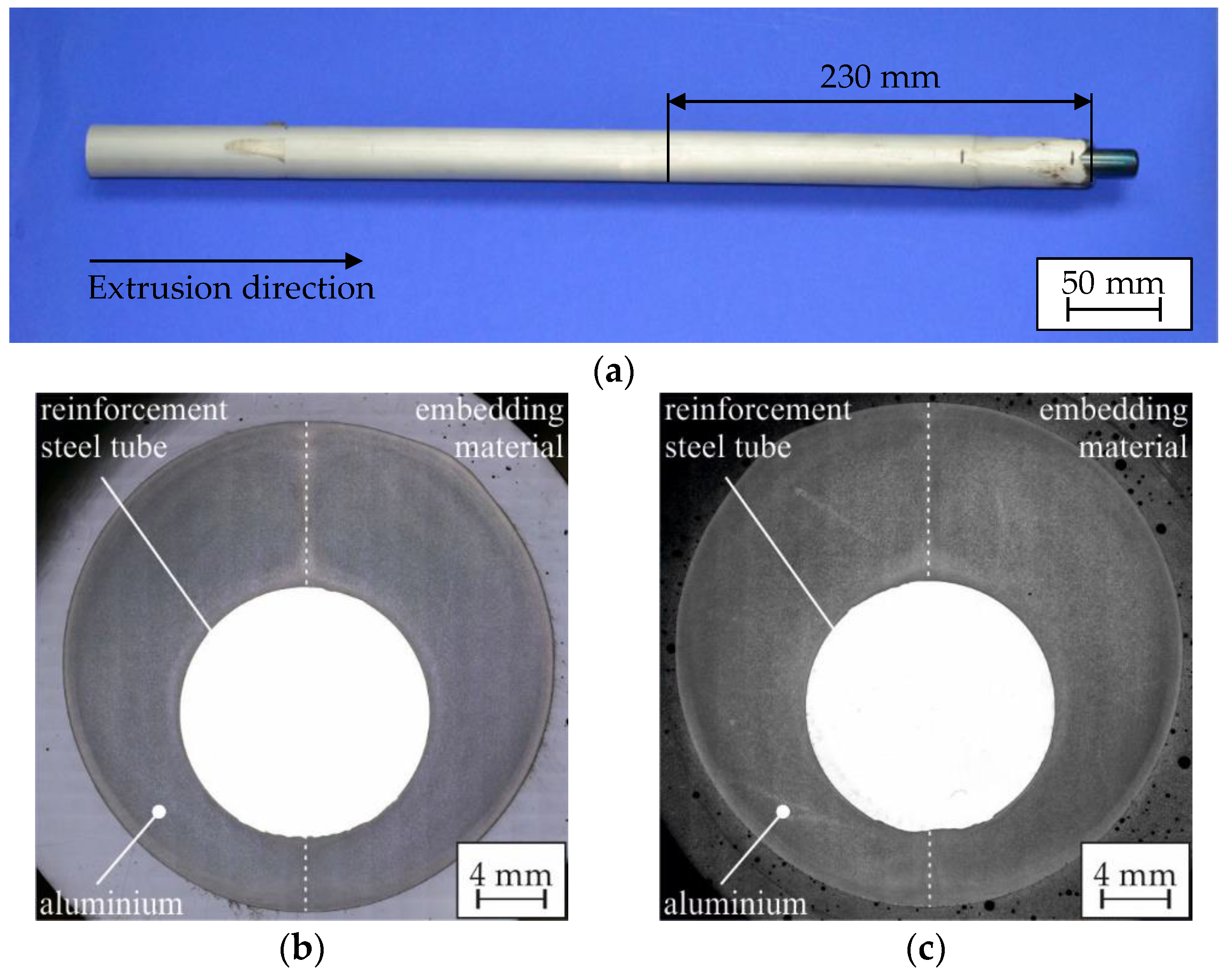
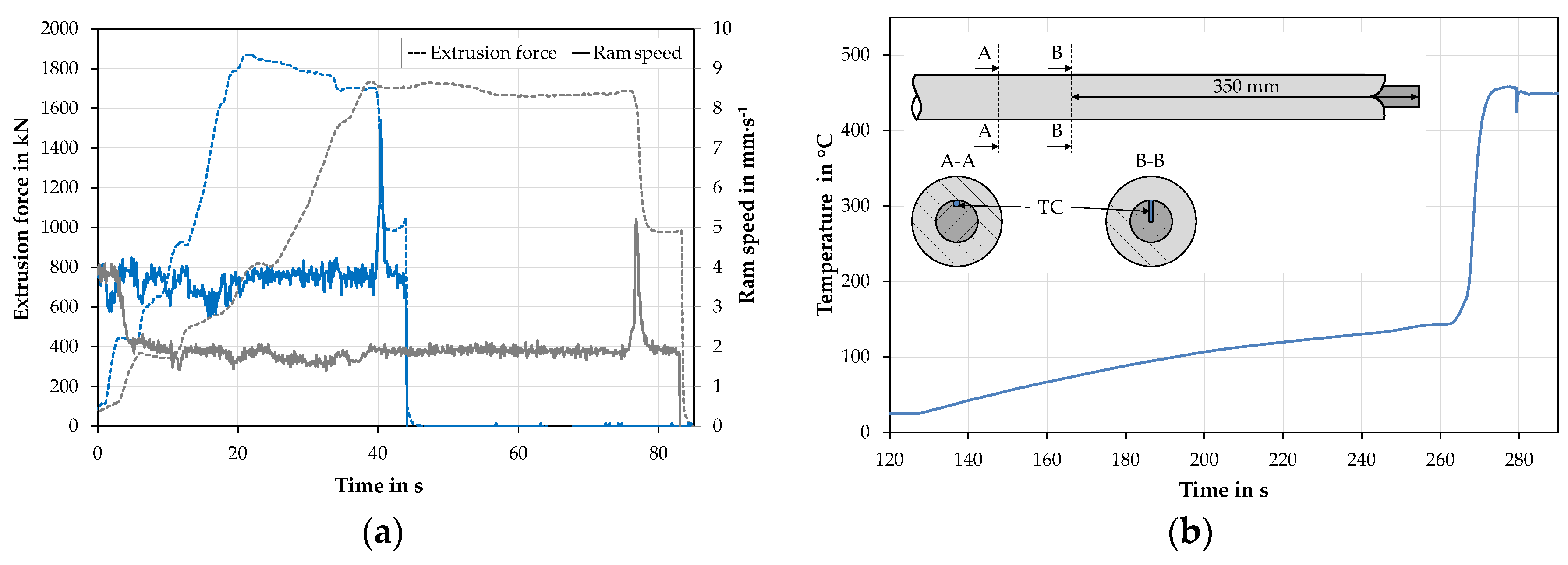
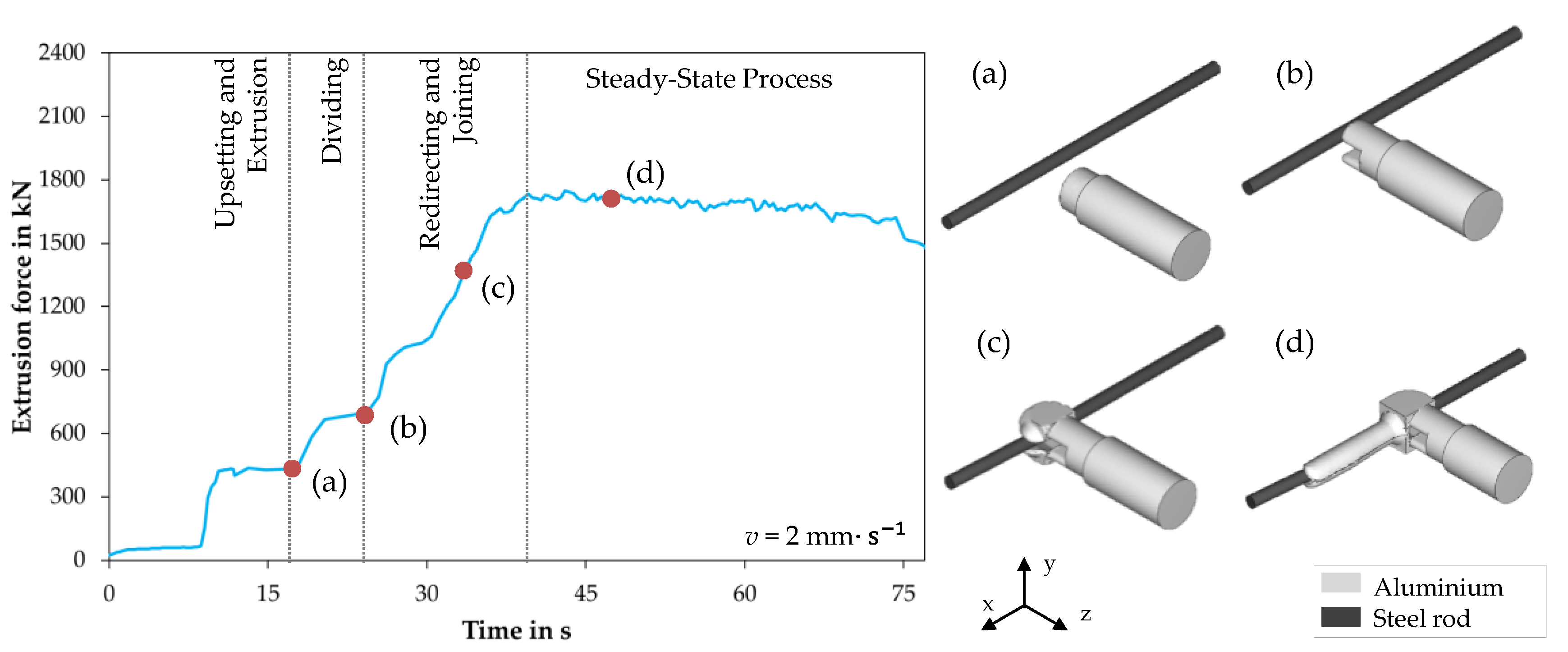
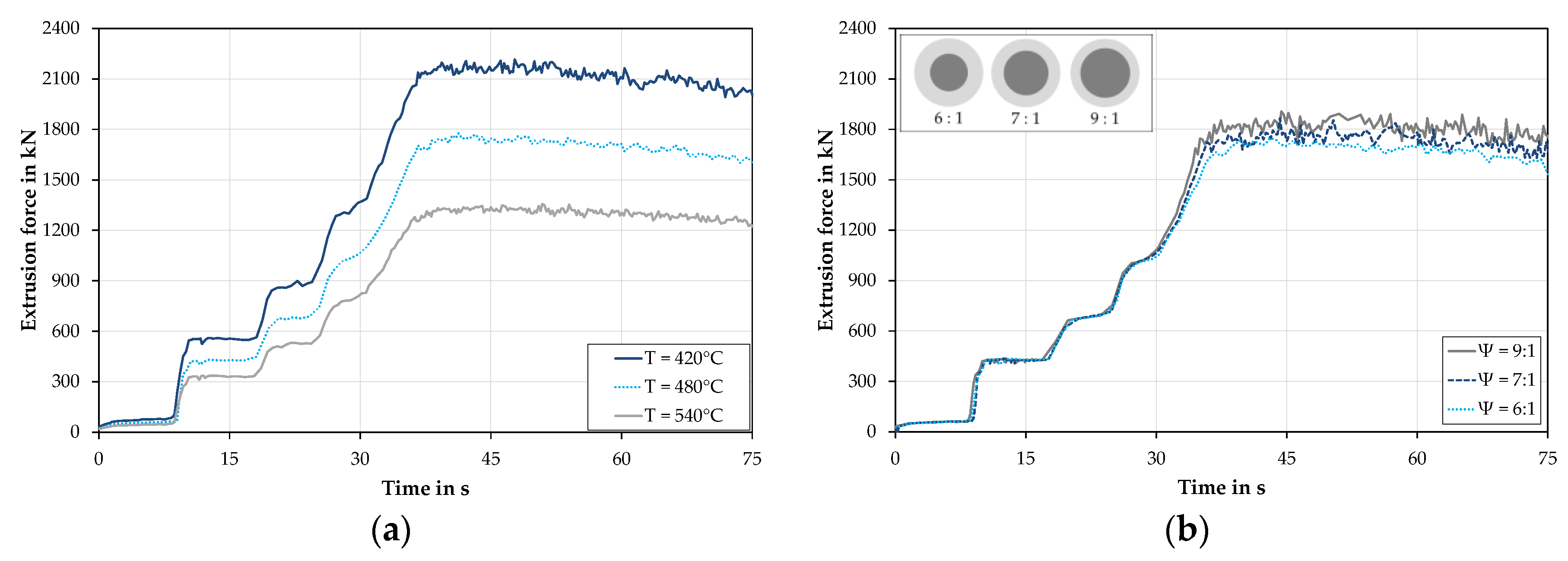
3.1. Extrusion Experiments

An exemplary hybrid profile obtained in the experiments with a ram speed of 2 mm·s−1 and an extrusion ratio of 6:1 is shown in Figure 3a. Although a flat and even profile surface without visible cracking or failure was achieved, slight variations of the outer diameter could be observed.
Each of the hybrid profiles was characterized metallographically. Images of the cross-sections shown in Figure 3b,c were recorded 230 mm behind the tip of the extruded aluminum. In order to determine the position of the longitudinal weld seam, a H2SO4/HF etching solution was used. An almost symmetric position of the weld seams was found for both ram speeds at the investigated location. It was shown previously in [2] that the weld seams were laterally displaced in the initial segment of the hybrid profile and that the displacement of the weld seams decreased during the extrusion process. Obviously, the steel reinforcement had not been positioned truly coaxially inside the profile in the shown cross-sections. This might be due to an asymmetric material flow inside the welding chamber and the loose fit of the steel rod in the supporting channel. However, the supporting channel successfully prevented the plastic deformation of the rod for the extrusion parameters employed. Only a slight influence of the ram speed on the position of the steel rod could be determined and no macroscopic gap or crack between the aluminum and the steel rod was observed.
Figure 4a shows the experimentally determined extrusion force-time diagrams and the determined ram speed of an extrusion experiment with a programmed ram speed of 2 mm·s−1 and 4 mm·s−1. The data showed that the extrusion force increased to 1740 kN and 1860 kN for ram speeds of 2 mm·s−1 and 4 mm·s−1, respectively. The extrusion force vs. time curves exhibited several plateaus in both cases, which was due to a consecutive filling of the different tool sections. After reaching the maximum extrusion force, the aluminum exited the die together with the reinforcing element and the extrusion force decreased. This corresponded to the extrusion force curve for direct extrusion and was due to the reduction in friction as the contact area between the aluminum billet and the inner container lining steadily decreased [19]. During this stage, the hybrid profile continuously emerged from the tool. The large drop at the end of the experiment was due to the steel rod leaving the die whereas the last decrease in force indicated the termination of the experiment. As can be observed from the ram speed-time curves, the experimentally determined ram speed deviated from the desired 2 mm·s−1 or 4 mm·s−1 at the start of the experiments. Here, faster speeds were selected manually to accelerate the filling of the die to ensure a constant temperature of the billet and tools. The intended ram speeds were reached when the extrusion force increased. As soon as the tool was filled with aluminum only, the ram speed increased abruptly for a short period of time. This correlated with the decreasing extrusion force and thus with a slightly delayed control of the extrusion press.
The measured temperature history of the steel rod is shown in Figure 4b. After insertion, the steel rod first heated up to approximately 140 °C through contact with the tool when the extrusion experiment started. Subsequently, the temperature further increased up to 458 °C due to direct contact with the extruded aluminum billet material. Based on these observations, the initial temperature of the steel rod was set to 140 °C in the numerical investigations. After 300 s, the temperature measurement was terminated when the thermocouple had been torn off due to the high contact pressure between the steel rod and aluminum.

3.2. Material Characterization

The billets used in this study consisted of the wrought aluminum alloy EN AW-6082, which was co-extruded with the case hardening steel 20MnCr5 using the described LACE process. The chemical composition of the materials employed in the present study were analyzed via spark spectrometry [20]. Based on the force-displacement curves obtained in the cylindrical upsetting experiments, the flow stresses k f were determined as a function of strain, strain rate, and forming temperature. The flow curves determined at the investigated temperatures and a strain rate of 1 s−1 are shown exemplarily in Figure 5a,b. The flow stress of the steel in the temperature range employed was more than ten times higher than the yield stress of the aluminum. As expected, both materials showed a strong dependence on the forming temperature and the strain rate. As the forming temperature increased, the material’s flow stress decreased, while the flow stress increased with increasing strain rate.
A uniaxial stress state and a negligibly small influence of friction could be assumed up to a true strain of ϕ = 0.7 in the upsetting experiments. Since significantly higher degrees of true strain are generated during extrusion, the recorded flow curves were extrapolated using suitable approaches. The respective parameters of the used Hensel and Spittel approach (Equation (1)) were determined by means of the method of the smallest error squares [21].
k f = A e ( m 1 T ) φ m 2 φ ˙ m 3
where k f describes the flow stress; A and m1 to m3 are the material-dependent parameters, which are presented in Table 3. The extrapolated flow curves were implemented in the FE software as a function of temperature, strain, and strain rate.

3.3. Numerical Results

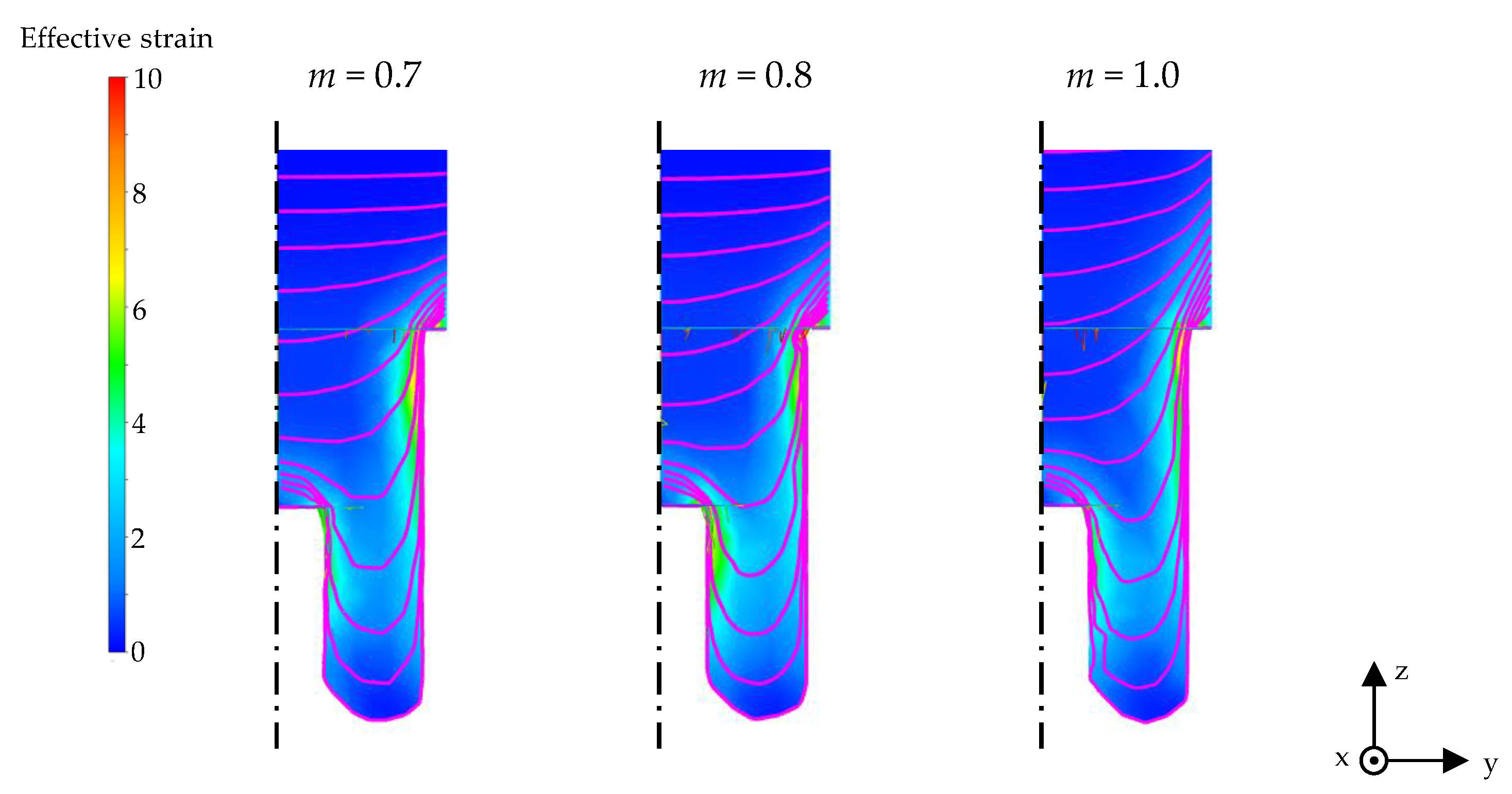
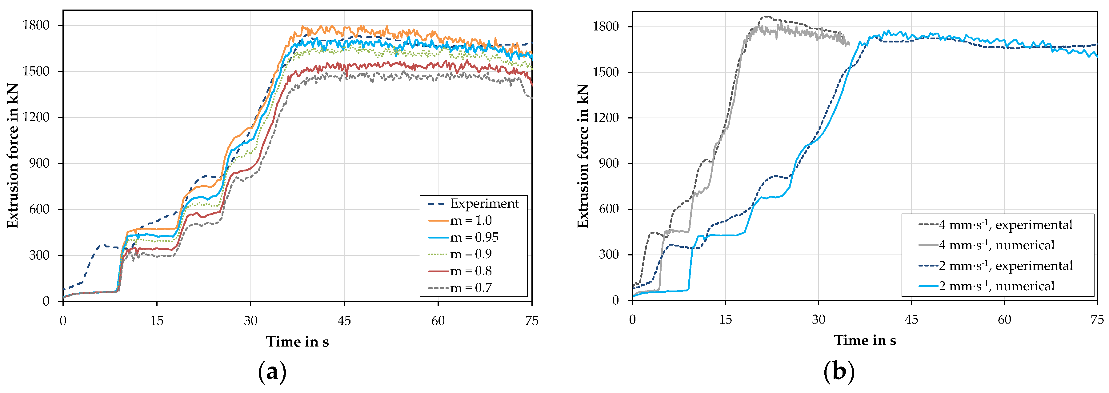
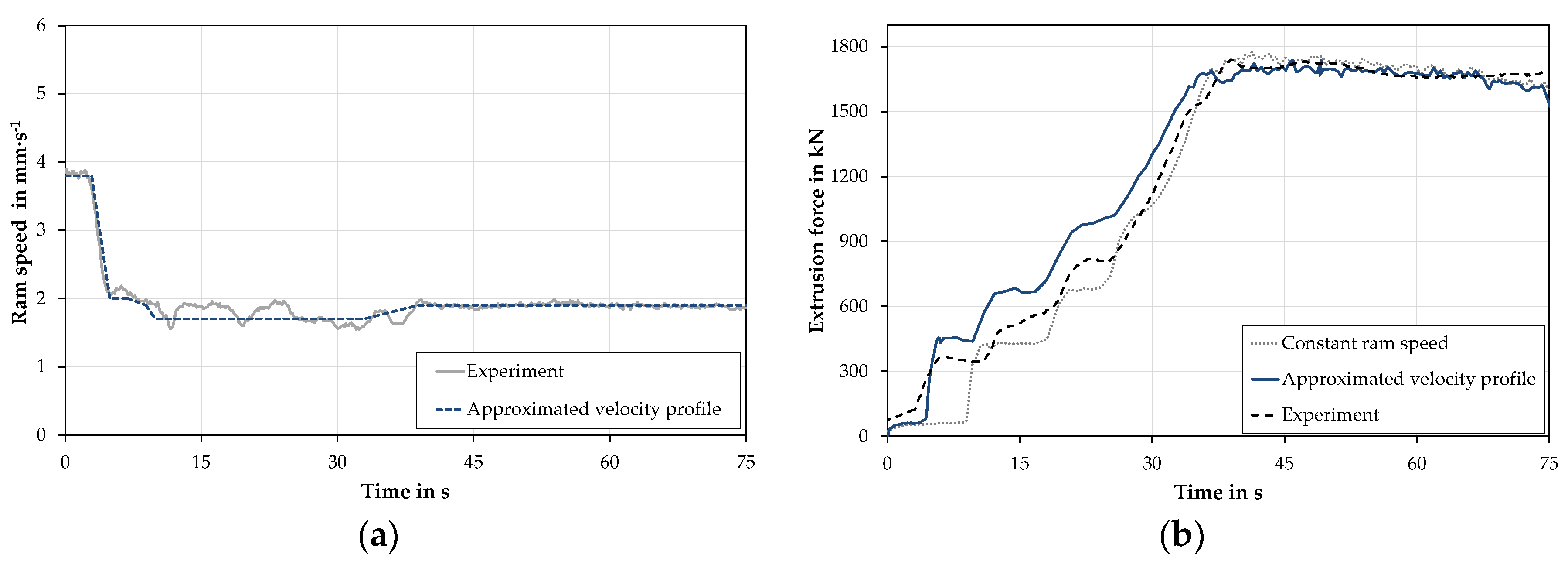
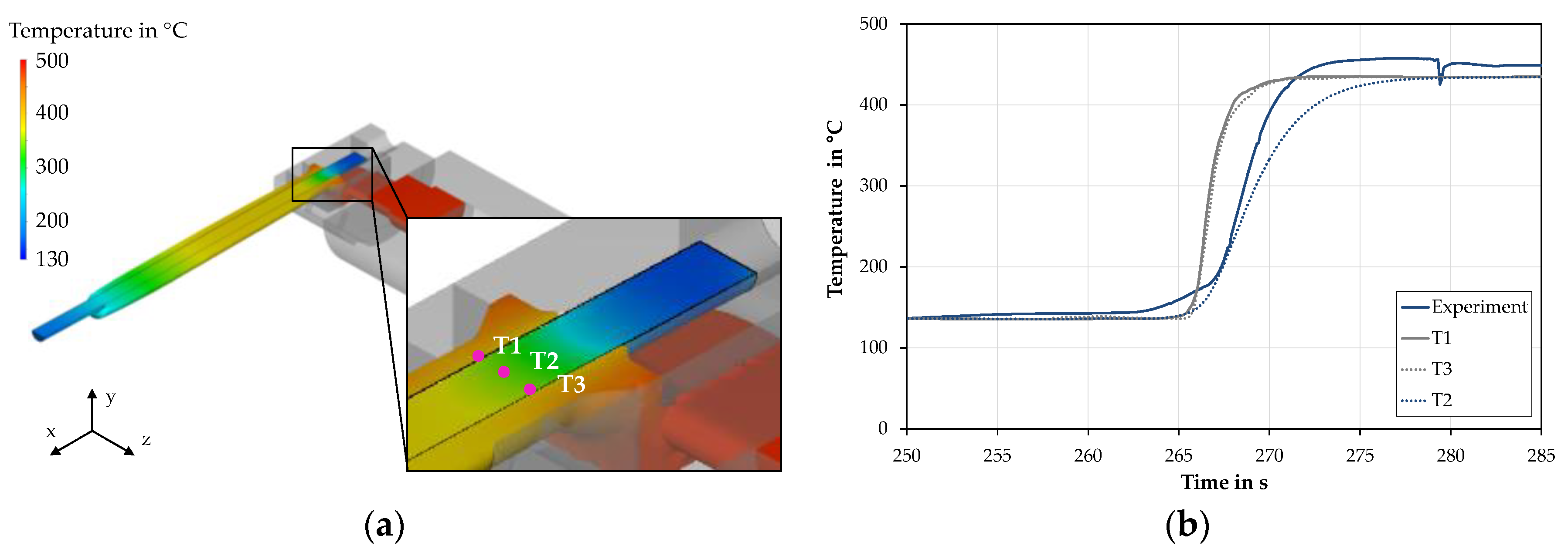
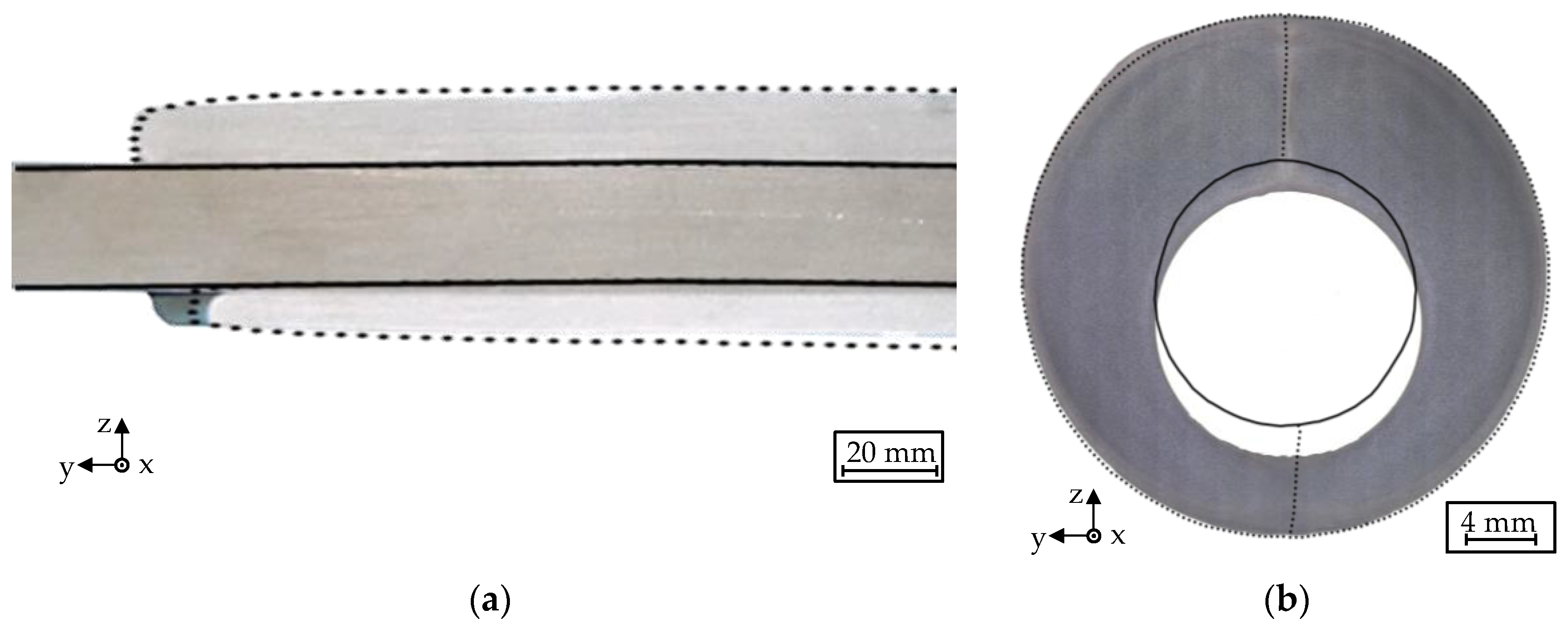
3.3.1. Material Flow and Determination of Friction Coefficient

As can be observed from the extrusion force-time curves, the extrusion force increased with the progressing flow of aluminum. This increase takes place in a couple of steps, which are highlighted in Figure 6 with the numerically modelled material flow for the corresponding stages of the process marked in the diagram with red dots. Initially, the billet is pressed in the negative z-direction by the dummy block. Upsetting of the aluminum billet in the container and the material flow through the initial forming stage with a smaller diameter occurs until point (a). At the top of the tool body, the aluminum alloy is divided in two material streams (b). Subsequently, the tool is filled and the aluminum alloy is redirected by an angle of 90°. In the welding chamber of the tool, both metal streams join and are welded while the material is extruded through the die, resulting in two longitudinal weld seams opposite each other (c). In the steady-state process (d), the extrusion force slightly decreases due to continuous shortening of the billet and the accompanying decreasing friction at the billet/container interface. At the end of the process, only aluminum is extruded due to the restricted length of the steel rod in the laboratory-scale investigations and thus, the extrusion force decreases further.
Tresca’s friction law was used to describe the frictional behavior between the aluminum billet and tool. The friction value was varied between 0.7 and 1.0 to determine the best correlation in comparison with the experimental results. In Figure 7, the influence of the friction value on the material flow inside the container and the upper part of the tool is shown. As the friction value increased, the aluminum was more stuck to the tool, which is illustrated by the highlighted flow lines. This also caused the characteristic shear zone near the first forming stage to increase.
The predicted force-time curves for a forming temperature of 480 °C and a ram speed of 2 mm·s−1 depending on different friction values are shown in Figure 8a. Depending on the considered friction value, maximum forces between 1450 kN and 1800 kN were achieved. In the experiment, a maximum force of 1740 kN was measured. It was obvious that the experimentally determined force-displacement curve was located between the calculated curves for m = 0.9 and m = 1. For this reason, an additional simulation with a friction coefficient of m = 0.95 was carried out, which is also shown in Figure 8a. In Figure 8b, a comparison between the measured and the predicted force-time curves with the considered friction value of m = 0.95 is shown for both ram speeds. It was observed that the extrusion force increased with increasing ram speed. At a ram speed of 4 mm·s−1, a maximum force of 1820 kN was calculated, which correlated with the experimental maximum value of 1860 kN. For a ram speed of 2 mm·s−1, a maximum force of 1750 kN was calculated. In both cases, a high degree of agreement with the experimental values was obtained. Therefore, a constant friction value of m = 0.95 was used for subsequent simulations, which agreed well with the friction values described in the literature for the extrusion of aluminum alloys [7,17]. A correspondence between the calculated and the measured force-time curve in the steady-state process could also be determined. The maximum force of the predicted force-time curve and the steady-state process were quite close to the experimentally determined force progression in both cases. The differences between the predicted and measured force-time curves in the beginning could be caused by the neglected elastic deformation of the tool in the numerical simulation as well as the variation of the ram speed at the beginning of the experimental investigations, which is shown in Figure 4a.
In order to investigate the influence of the non-constant velocity profile on the force-displacement curve, the experimental ram speed curve was approximated as shown in Figure 9a and implemented in the numerical simulation. By means of the approximated speed profile, a significant improvement in the temporal correspondence of the gradual increase in the extrusion force profile could be achieved. However, a slight difference in the height of the various levels was still evident. As the maximum force in the steady-state process is only slightly influenced by using the approximated ram speed curve, a constant ram speed was used for further investigations to reduce computation time.
In the next step, the heat transfer coefficient used in the simulation was adjusted and validated using the temperature measurement from the experimental extrusion test. Figure 10a shows the positions of the temperature measurement points in the simulation and the temperature distribution in the profile during extrusion. Temperature measurement point T2 was equivalent to the position of the thermocouple in the experimental investigation. The results showed that the steel rod was initially heated in the tool by heat conduction at the beginning of the experiment. As soon as the rod reached the die, it heated up to a temperature of approximately 300 °C. After it exited the die, the profile cooled down continuously by exposure to ambient air. Figure 10b gives a comparison of the measured and the calculated temperature curves for a heat transfer coefficient of 35 kW·m−2·K−1. At the peripheral measuring points (T1, T3), the temperature rose quickly due to the direct contact with aluminum. In the middle of the steel rod (T2), the temperature rose correspondingly slower than at the surface. The comparison with the experimental data showed good agreement in the progression and the level of the temperature values, with a difference of less than 5% between the calculated and measured temperature at the end of the measurement.
In order to compare the calculated geometry of the extruded profile with the actual one resulting from the experiments, the metallographic cross-sections of the profiles were analyzed. In addition, an extruded profile was cut lengthwise in the area of the longitudinal weld seams by means of wire-cut electrical discharge machining (EDM) in order to compare the measured and simulated contours of the aluminum and steel rod in the xz plane. The simulated contours were exported and overlaid with the images of the extruded profiles, as shown in Figure 11. There was good correlation between the simulated and the experimental contours in the longitudinal section in Figure 11a. The image indicates that the aluminum alloy advanced in the x-direction in the upper half of the compound profile, caused by an uneven material flow in the welding chamber. This caused the steel rod to be pressed in the negative z-direction, resulting in a significantly smaller amount of aluminum on the other side of the steel rod, which was obvious from the cross sections of the hybrid profiles. In addition, the non-coaxial position of the steel rod was more pronounced in the experiment than in the numerical results (Figure 11b). However, the same tendency could be observed. The smaller displacement of the steel rod in the numerical simulation could be due to an adjustment of the geometry of the supporting channel performed in the FE simulation. The inner diameter of the supporting channel was reduced in order to avoid elements being drawn into the gap between the steel rod and tool, which would lead to the calculation being aborted due to extensive element distortions. As a result, a significantly more centric position of the reinforcement was achieved in the simulations. However, a comparison between the calculated and the experimental positions of the longitudinal weld seam showed that the numerical simulation represented the result of the experiments quite well, which was most clearly visible for the upper weld seam in Figure 11b.
In summary, good agreement between the experimental and numerical results considering the force-time and temperature-time curves as well as the geometry was achieved. Based on this validated simulation model, further investigations on the influence of the boundary conditions on the force-time curve and material flow were carried out to determine a possible process window for further experimental extrusion tests.

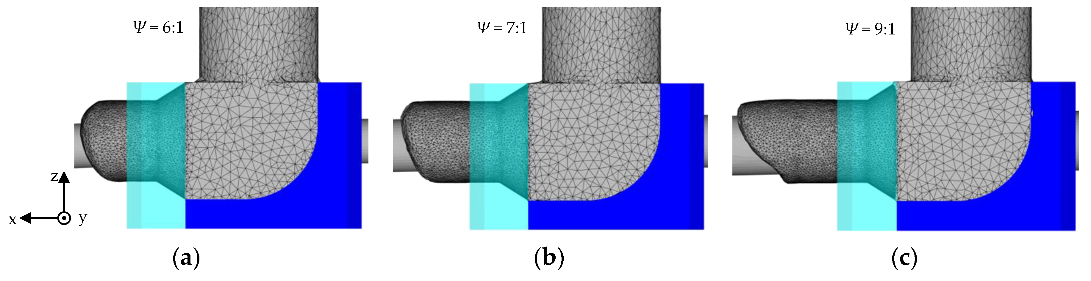
3.3.2. Parametric Study

In order to determine possible boundary conditions for further experimental investigations and avoid costly trial-and-error experiments, a numerical parameter study was carried out. In the simulations, extrusion temperature, ram speed, and extrusion ratio were varied and their influence on the extrusion force curves and material flow were determined. As shown in Figure 12a, the billet temperature had a significant influence on the maximum extrusion force. With decreasing temperature, the extrusion force increased. However, the maximum extrusion force of the employed 2.5 MN extrusion press was not exceeded, even for the lowest billet temperature of 420 °C.
The calculated force-time curves depending on different extrusion ratios as well as schematic representations of the resulting cross-sections of the profiles are shown in Figure 12b. As expected, the maximum extrusion force slightly increased with the extrusion ratio, but did not exceed 2.5 MN, which equaled the experimentally available maximum extrusion force. In addition, the numerical results showed that the calculated contact pressure between the aluminum and steel in the welding chamber increased with increasing extrusion ratio. For an extrusion ratio of 6:1, values of approx. 210 MPa were achieved, whereas contact pressures of more than 300 MPa occurred at an extrusion ratio of 9:1. Figure 13 shows the material flow in the tool depending on the extrusion ratios investigated after a stroke of 74 mm of the dummy block. Here, higher extrusion ratios were realized by an enlarged diameter of the steel rod, while the outer diameter of the die remained constant. The results showed that the outflow velocity of aluminum increased with the extrusion ratio and that the material flow became significantly more asymmetrical for higher extrusion ratios. Due to the smaller cross-sectional area available to the aluminum alloy, the asymmetry of the material flow increased.
Considering the simulation results, none of the investigated parameters led to a deformation of the steel rod and for this reason, should be suitable for experimental investigations. In the experimental investigations as described above, even at the smallest extrusion ratio, a higher tilting of the steel rod could be determined than in the numerical results. Since it could be shown by the numerical investigations that the advance of the aluminum alloy in the positive z-direction increased with increasing extrusion ratio, it can be assumed that the tilt of the steel rod in the experimental investigations will be even more significant for higher pressing ratios. Due to the asymmetrical material flow especially at higher extrusion ratios, a modified tool geometry was designed, which will be used for an upscaling of these experiments to a near-industrial scale.

4. Conclusions and Outlook

A lateral angular co-extrusion (LACE) process for the production of coaxial aluminum-steel compound profiles was presented. Hybrid semi-finished products were produced by LACE at 480 °C with an outer diameter of 28 mm and a length of about 600 mm at ram speeds of 2 mm·s−1 and 4 mm·s−1. The proposed setup resulted in a mostly uniform hybrid profile with no sleeve cracking or plastic deformation of the steel rod for the process parameters used. The longitudinal weld seams were mostly symmetric and no macroscopic gap was observed between the different materials. It could be seen that a slight eccentricity of the steel rod occurred during the experiments, which could be observed in the cross sections as well as the longitudinal sections of the profiles.
An FE model, which was validated by the experimental results, was built up and used to examine the influence of different process parameters on the developed LACE process. The established FE model was able to predict material flow, extrusion force, and temperature development as well as geometrical shape in good agreement with the experimental results. Due to the tool geometry that was adapted for the FE simulation, the displacement of the steel rod was somewhat smaller than in the investigated compounds.
Billet temperature and ram speed have a significant influence on the maximum extrusion force. An increase in the extrusion force could be observed with decreasing temperature and increasing ram speed. However, the maximum extrusion force of the extrusion press of 2.5 MN did not exceed any of the parameters employed. It was found that the extrusion ratio had a significant influence on the material flow inside the tool. Due to the smaller cross-section of the extruded aluminum alloy, the asymmetry of the shape of material flow increased with rising extrusion ratio.
Based on these results, an extrusion tool with a modified geometry to improve material flow will be used for subsequent experiments on a near-industrial scale. These co-extrusion experiments will be carried out using a 10 MN extrusion press to produce hybrid semi-finished workpieces for the subsequent die forging process. For better insight into the temperature development during the process, thermocouples will be integrated into the die. In order to further improve the numerical process design, the formation of intermetallic phases during the co-extrusion process will be examined in future studies and taken into account in the numerical simulations.

Author Contributions

B.-A.B., J.U., N.H. and A.C. designed the numerical model and performed the parametric study as well as the validation of the model; C.K. and S.E.T. designed and performed the co-extrusion experiments; J.U. and S.E.T. wrote the paper.

Funding

This research was funded by the Deutsche Forschungsgemeinschaft (DFG, German Research Foundation) grant number 252662854. The APC was funded by the Deutsche Forschungsgemeinschaft (DFG, German Research Foundation).

Acknowledgments

The results presented in this paper were obtained within the Collaborative Research Centre 1153 “Process chain to produce hybrid high performance components by Tailored Forming” in the subproject A01, funded by the Deutsche Forschungsgemeinschaft (DFG, German Research Foundation)—252662854. The flow curves presented in this paper were obtained in cooperation with subproject C1 of the Collaborative Research Centre 1153. The authors thank the German Research Foundation (DFG) for their financial support of this project.

Conflicts of Interest

The authors declare no conflict of interest.

References

  1. Hirsch, J. Aluminium in innovative lightweight car design. Mater. Trans. 2011, 52, 818–824. [Google Scholar] [CrossRef]
  2. Thürer, S.E.; Uhe, J.; Golovko, O.; Bouguecha, A.; Klose, C.; Behrens, B.A.; Maier, H.J. Co-extrusion of semi-finished aluminium-steel compounds. In Proceedings of the 20th International ESAFORM Conference on Material Forming, Dublin, Ireland, 26–28 April 2017; AIP Publishing: Melville, NY, USA; pp. 140002-1–140002-6. [Google Scholar]
  3. Grittner, N.; Striewe, B.; Hehl, A.V.; Bormann, D.; Hunkerl, M.; Zoch, H.W.; Bach, F.W. Co-Extrusion of Aluminium-Titanium-Compounds. Key Eng. Mater. 2012, 491, 67–74. [Google Scholar] [CrossRef]
  4. Behrens, B.A.; Overmeyer, L.; Barroi, A.; Firschkorn, C.; Hermsdorf, J.; Kaierle, S.; Stonis, M.; Huskic, A. Basic study on the process combination of deposition welding and subsequent hot bulk forming. Prod. Eng. Res. Dev. 2013, 7, 585–591. [Google Scholar] [CrossRef]
  5. Duan, X.; Velay, X.; Sheppard, T. Application of finite element method in the hot extrusion of aluminium alloys. Mater. Sci. Eng. A 2004, 369, 66–75. [Google Scholar] [CrossRef]
  6. Li, Q.; Harris, C.; Jolly, M.R. Finite element modelling simulation of transverse welding phenomenon in aluminium extrusion process. Mater. Des. 2003, 24, 493–496. [Google Scholar] [CrossRef]
  7. Chanda, T.; Zhou, J.; Duszczyk, J. Application of three-dimensional numerical simulation to analysis of development of deformation zone at beginning of aluminium extrusion process. Mater. Sci. Technol. 2001, 17, 70–74. [Google Scholar] [CrossRef]
  8. Lu, X.; Zhang, C.; Zhao, G.; Guan, Y.; Chen, L.; Gao, A. State-of-the-art of extrusion welding and proposal of a method to evaluate quantitatively welding quality during three-dimensional extrusion process. Mater. Des. 2016, 89, 737–748. [Google Scholar] [CrossRef]
  9. Kazanowski, P.; Epler, M.E.; Misiolek, W.Z. Bi-metal rod extrusion-process and product optimization. Mater. Sci. Eng. A 2004, 369, 170–180. [Google Scholar] [CrossRef]
  10. Priel, E.; Ungarish, Z.; Navi, N.U. Co-extrusion of a Mg/Al composite billet: A computational study validated by experiments. J. Mater. Process. Technol. 2016, 236, 103–113. [Google Scholar] [CrossRef]
  11. Schwane, M.; Citrea, T.; Dahnke, C.; Haase, M.; Khalifa, N.B.; Tekkaya, A.E. Simulation of composite hot extrusion with high reinforcing volumes. Proc. Eng. 2014, 81, 1265–1270. [Google Scholar] [CrossRef]
  12. Kleiner, M.; Schomäcker, M.; Schikorra, M.; Klaus, A. Manufacture of Extruded and Continuously Reinforced Aluminum Profiles for Ultra-Lightweight Constructions, Herstellung verbundverstaerkter Aluminiumprofile fuer ultraleichte Tragwerke durch Strangpressen. Mater. Werkst. 2004, 35, 431–439. [Google Scholar] [CrossRef]
  13. Pfeiffer, I.; Foydl, A.; Kammler, M.; Matthias, T.; Kosch, K.-G.; Jäger, A.; Khalifa, N.B.; Tekkaya, A.E.; Behrens, B.-A. Compound Forging of Hot-extruded Steel-reinforced Parts. In Proceedings of the 14th International Conference on Metal Forming, METAL FORMING 2012, Krakow, Poland, 16–29 September 2012; pp. 159–162. [Google Scholar]
  14. Tham, L.M.; Gupta, M.; Cheng, L. Effect of reinforcement volume fraction on the evolution of reinforcement size during the extrusion of Al-SiC composites. Mater. Sci. Eng. A 2002, 326, 355–363. [Google Scholar] [CrossRef]
  15. Pietzka, D.; Khalifa, N.B.; Gerke, S.; Tekkaya, A.E. Composite extrusion oft thin aluminum profiles with high reinforcing volume. Key Eng. Mater. 2013, 554–557, 801–808. [Google Scholar] [CrossRef]
  16. Lange, K. Handbook of Metal Forming; Society of Manufacturing Engineers: State College, PA, USA, 1994; ISBN 9780872634572. [Google Scholar]
  17. Flitta, I.; Sheppard, T. Nature of friction in extrusion process and its effect on material flow. Mater. Sci. Technol. 2013, 19, 837–846. [Google Scholar] [CrossRef]
  18. Duan, X.; Sheppard, T. Simulation and control of microstructure evolution during hot extrusion of hard aluminium alloys. Mater. Sci. Eng. A 2003, 351, 282–292. [Google Scholar] [CrossRef]
  19. Bauer, M.; Sauer, G.; Siegert, K. Strangpressen, 2nd ed.; Aluminium-Verlag: Düsseldorf, Germany, 2001; ISBN 3870172495. [Google Scholar]
  20. Thürer, S.E.; Uhe, J.; Golovko, O.; Bonk, C.; Bouguecha, A.; Behrens, B.-A.; Klose, C. Mechanical Properties of Co-Extruded Aluminium-Steel Compounds. Key Eng. Mater. 2017, 742, 512–519. [Google Scholar] [CrossRef] [Green Version]
  21. Hensel, A.; Spittel, T. Kraft-Und Arbeitsbedarf Bildsamer Formgebungsverfahren; VEB Deutscher Verlag für Grundstoffindustrie: Leipzig, Germany, 1978. [Google Scholar]
Figure 1. (a) 2.5 MN extrusion press (Müller engineering GmbH, Todtenweis, Germany); (b) Longitudinal section of LACE tool and container.
Metals 08 00717 g001
Figure 2. (a) 3D FE model of the assembly; (b) Influence of the minimal element edge length on the predicted extrusion force and computation time.
Metals 08 00717 g002
Figure 3. Hybrid aluminum-steel compounds co-extruded at 480 °C: (a) Overview image; (b) Metallographic image of the cross-section after a profile length of 230 mm for a ram speed of 2 mm·s−1; (c) Metallographic cross-section after a profile length of 230 mm for a ram speed of 4 mm·s−1.
Metals 08 00717 g003
Figure 4. (a) Extrusion force-time diagrams and ram speed-time diagrams obtained experimentally at an average ram speed of 2 mm·s−1 (grey) and 4 mm·s−1 (blue); (b) Experimentally measured temperature of the steel rod for a ram speed of 2 mm·s−1 with schematically displayed position of the thermocouple (TC).
Metals 08 00717 g004
Figure 5. Flow curves at a strain rate of 1 s−1 for various temperatures of (a) EN AW-6082 and (b) 20MnCr5.
Metals 08 00717 g005
Figure 6. Extrusion force-time diagram with highlighted process steps and numerical modelling of the material flow during the co-extrusion of aluminum and steel: (a) upsetting and extrusion; (b) dividing into two material streams; (c) filling of the tool, redirection and joining; (d) forming and steady material flow.
Metals 08 00717 g006
Figure 7. Material flow highlighted in the container and the upper part of the tool for different friction values.
Metals 08 00717 g007
Figure 8. (a) Numerically predicted force-time curves for different friction values; (b) Comparison of numerically predicted and experimentally measured force-time curves for ram speeds of 2 mm·s−1 and 4 mm·s−1 (m = 0.95).
Metals 08 00717 g008
Figure 9. (a) Measured and approximated ram speed-time curve; (b) Extrusion force-time curve for a temperature of 480 °C, an extrusion ratio of 6:1 for constant and approximated ram speed.
Metals 08 00717 g009
Figure 10. (a) Calculated temperature distribution during extrusion and highlighted temperature measurement points T1–T3; (b) Comparison of the calculated temperature curves at measurement points T1–T3 with the experimental results.
Metals 08 00717 g010
Figure 11. Geometrical comparison between the simulated contour and experimental results for a ram speed of 2 mm·s−1. The outer contour of the extruded aluminum component is represented by the black dotted line, the outer contour of the steel rod by the continuous black line: (a) Longitudinal view; (b) Cross-section at a distance of 230 mm behind the tip of the aluminum component.
Metals 08 00717 g011
Figure 12. (a) Numerically predicted force-time curves for an extrusion ratio of 6:1 for different billet temperatures at a ram speed of 2 mm·s−1; (b) For different extrusion ratios at a billet temperature of 480 °C and a ram speed of 2 mm·s−1.
Metals 08 00717 g012
Figure 13. Material flow inside the tool and through the die after a stroke of the dummy block of 74 mm. (a) For an extrusion ratio of 6:1; (b) For an extrusion ratio of 7:1; (c) For an extrusion ratio of 9:1.
Metals 08 00717 g013
Table 1. Billet and steel rod dimensions.
DimensionValue in mm
Billet length180
Billet diameter56
Steel rod length400
Steel rod diameter15.2
Table 2. Process parameters used in the numerical parametric study.
Boundary ConditionValues
Billet and tool temperature T in °C420, 480, 540
Ram speed v in mm·s−12, 4
Diameter of the steel rod d in mm15.2, 18, 20
Extrusion ratio Ψ6:1, 7:1, 9:1
Table 3. Determined material-dependent parameters of the Hensel–Spittel flow curve approach for EN AW-6082.
Material ParameterAm1m2m3
Value317.6−0.004290.0550.089

