Edge-Drop Control Behavior for Silicon Strip Cold Rolling with a Sendzimir Mill
by
Hongbo Li
1,*, 
Zhenwei Zhao
1,
Dawei Dong
1,
Guomin Han
1,
Jie Zhang
1,
Haichao Liu
2 and
Xuechang You
2 1
School of Mechanical Engineering, University of Science and Technology Beijing, Beijing 10083, China
2
Shougang Co., Ltd., Qian’an Steel Corp., Tangshan 064400, China
*
Author to whom correspondence should be addressed.
Metals 2018, 8(10), 783; https://doi.org/10.3390/met8100783
Submission received: 4 September 2018
/
Revised: 25 September 2018
/
Accepted: 26 September 2018
/
Published: 30 September 2018
(This article belongs to the Special Issue 5th UK-China Steel Research Forum)
Abstract
:Edge-drop control is important for silicon strip cold rolling, as the silicon strip is mainly used as a laminated core. Moreover, cold rolling is the key process for the thin strip edge-drop control, and a Sendzimir mill is one of the most popular cold rolling mills for silicon strips. Thus, the mastery of edge-drop control behavior for silicon strip cold rolling with a Sendzimir mill is beneficial for the improvement of the strip profile quality. With the finite element method, two models are built to analyze the edge-drop control behavior, one is the roll system and strip integrated elastic-plastic deformation statics model, and the other is the strip plastic deformation dynamics model. The first model provides the roll gap contour for the second model, then the strip profile can be calculated in the second model, which considers the transverse flow of the metal. Firstly, the compositions of edge-drop for the silicon strip are analyzed systematically, which are the edge-drop for work roll bending, the edge-drop for work roll flattening, and the edge-drop for transverse flow of the metal. Secondly, the influence of different rolling process parameters on the three parts are analyzed, such as the entrance thickness, the rolling reduction, the rolling tension, and so on; further, the influence of the roll contours are also analyzed. Finally, the edge-drop control behavior of the different rolling process parameters and roll contours are obtained. The research results provide theoretical guidance for edge drop control in the Sendzimir mill.
1. Introduction
Cold-rolled silicon strips, which are widely used in manufacturing production such as for motors and transformers, is an important soft magnetic functional material in the power electronics industry. Due to the requirement of service performance, the quality of the silicon strip transverse thickness deviation directly affects the performance of the laminated core, and the heat and efficiency of the entire product, which has a great influence on the performance of the motor. Therefore, there is a higher quality requirement for the transverse thickness deviation of the silicon strip [1,2]. The production practice shows that the transverse thickness deviation of silicon strip mainly results from the edge drop, so that the effective control of edge-drop can improve the quality of the transverse thickness deviation and increase the yield rate of the strips [3,4,5]. The universal crown mill (UCM) cold rolling mill, four-high rolling mill, six-high rolling mill and the Sendzimir mill are all common equipment for the production of cold-rolled silicon strips. The Sendzimir mill, with a small working roll diameter, the large overall stiffness of the rolling mill, and rich edge-drop control methods, is the mainstream mill for the production of cold-rolled silicon strips. However, the edge-drop control for the silicon strips has always been a research hotspot of various mills [6,7,8].
In past years, many researchers had focused on edge-drop control, and some positive results have been obtained [9,10,11,12]. Cao et al. [13] built a three-dimensional finite element model of roll stacks and strip deformation and analyzed the integrated design of roll contours for strip edge drop and crown control in tandem cold rolling mills. Chang et al. [14], Lu et al. [15], and Xuan et al. [16] proposed the reasons of edge drop in the silicon strips cold rolling for the four-high rolling mills and six-high rolling mills, and the edge drop was improved to a certain extent. Malik and Grandhi [17] proposed a new computational method for predicting the statics cross-sectional thickness profile of the rolled strips. Yu et al. [18] developed the software SM4SM based on the contact element double coordinate method to accurately predict the edge drop of silicon strips under different rolling conditions. Hamada et al. [19] performed numerical calculations on the edge drop of the Sendzimir mill through the influence function method, and studied the influence of the three-dimensional deformation of the small-diameter work rolls on the edge drop and the high-order waves of the silicon strips. Zhang et al. [20] and Liu et al. [21] established the finite element model of the 20-high mill to analyze the effect of different control methods of the mill on the roll gap. Cho and Hwang [22] put forward a mathematical model to predict the strip exit profile of the Sendzimir mill based on the finite element simulation results. Yuan et al. [23] used the boundary integral equation method to establish a flattening model between the rolls of the Sendzimir mill, and studied the edge drop caused by the elastic flattening of the work rolls. The above research results achieved a relatively accurate calculation of the edge drop. However, quantitative analysis of the composition of silicon strip edge drop in the Sendzimir mill was not carried out, so it is impossible to quantitatively analyze the main sources of silicon strip edge drop in the Sendzimir mill.
During the rolling process of the Sendzimir mill in actual production, the transverse thickness deviation of the cold-rolled silicon strips cannot meet the customers’ requirements after trimming, so the problem of the silicon strip edge drop control needs to be solved urgently. In order to effectively control the silicon strip edge drop, the edge-drop control behavior for silicon strip cold rolling with the Sendzimir mill must be mastered. In this paper, the roll system and the strip integration elastic-plastic deformation statics model, as well as the strip plastic deformation dynamics model, are established to quantitatively analyze the composition of the edge drop for the silicon strips, and the influence of different rolling process parameters and roll contours on the composition of the edge drop. The results provide a theoretical guide for silicon strip edge drop control in the Sendzimir mill.
2. Establishment and Verification of the Simulation Model of Silicon Strip Rolling Process
In this paper, the following methods are used to establish the finite element simulation model: a roll system and strip integration elastic-plastic deformation statics model and a strip plastic deformation dynamics model are established. On the one hand, the statics model is used to analyze the roll gap contours under different rolling process parameters such as the entrance thickness, the rolling reduction, the entrance and exit tensions, the roll shifting, the friction coefficient, as well as the roll contour configurations. On the other hand, the dynamics model, whose work roll is set as a rigid roll, takes the roll gap contour obtained in the statics model as the initial roll contour to simulate the rolling process of the silicon strips, and calculates the exit profile of the silicon strips and the transverse flow of the metal under different factors. This approach takes the advantages of the statics model and the dynamics model into consideration, and uses an indirect method to achieve the application of different rolling process factors in the dynamics model. Then, the transverse flow of the metal that meets the actual rolling conditions is obtained. The approach significantly reduces the calculation time and improves the calculation efficiency [24].
2.1. Roll System-Strip Integrated Statics Model
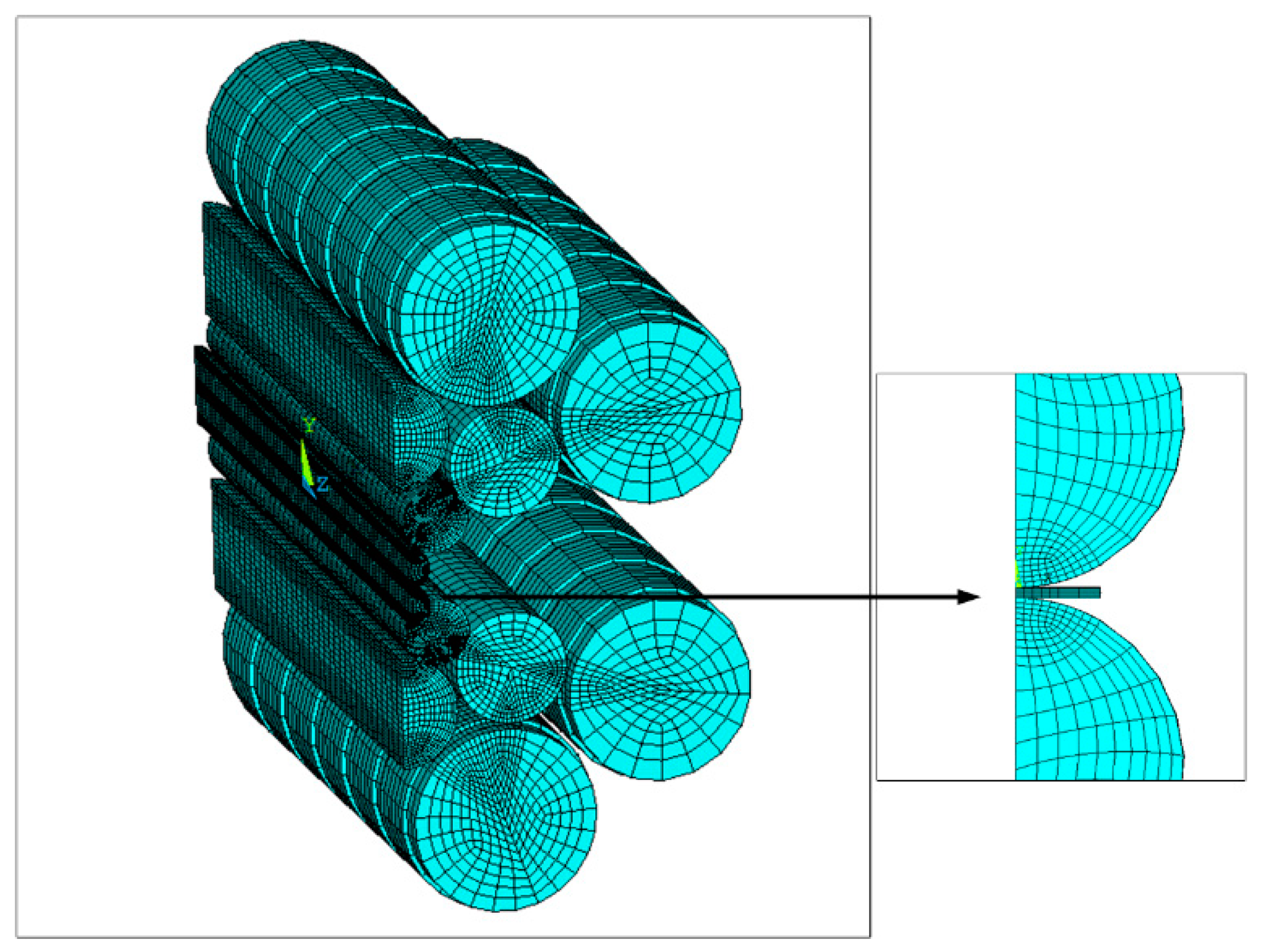
A certain Sendzimir mill has a longitudinal anti-symmetry for the work rolls and the first intermediate rolls. Based on the actual production, the geometrical and physical parameters of the rolls and the silicon strip are shown in Table 1. Considering the bilateral symmetry of the rolls, a three-dimensional elastic-plastic finite element simulation analysis model, including the roll system and the strip, is established using the common ANSYS finite element software (ANSYS 15.0, ANSYS Inc., Pittsburgh, PA, USA, as shown in Figure 1), and the roll gap contours are calculated under different factors. In the modeling process, it is assumed that each roll is a homogeneous isotropic material, and the friction between the rolls, the work roll, and the strip is the Coulomb friction.
Considering the deformation of the roll system, a soft–soft contact pair was established between the rolls, the roll, and the strip when setting the contact pairs of the finite element model. The contact units were attached to the contact surface between the rolls. The upper contact surface was designated as the target surface, whose unit type is TARGET170. The lower contact surface was designated as the contact surface, whose unit type was TARGET174. Finally, a total of 14 face–face contact pairs were established in the finite element model. In the unit division of the model, the SOLID186 element is selected in the contact areas of the rolls, and the rest was meshed by the SOLID185 element. In order to ensure the calculation accuracy of the statics model, the contact areas of the rolls and the edge of the silicon strip are subdivided. Finally, there were 192,158 elements and 371,513 nodes.
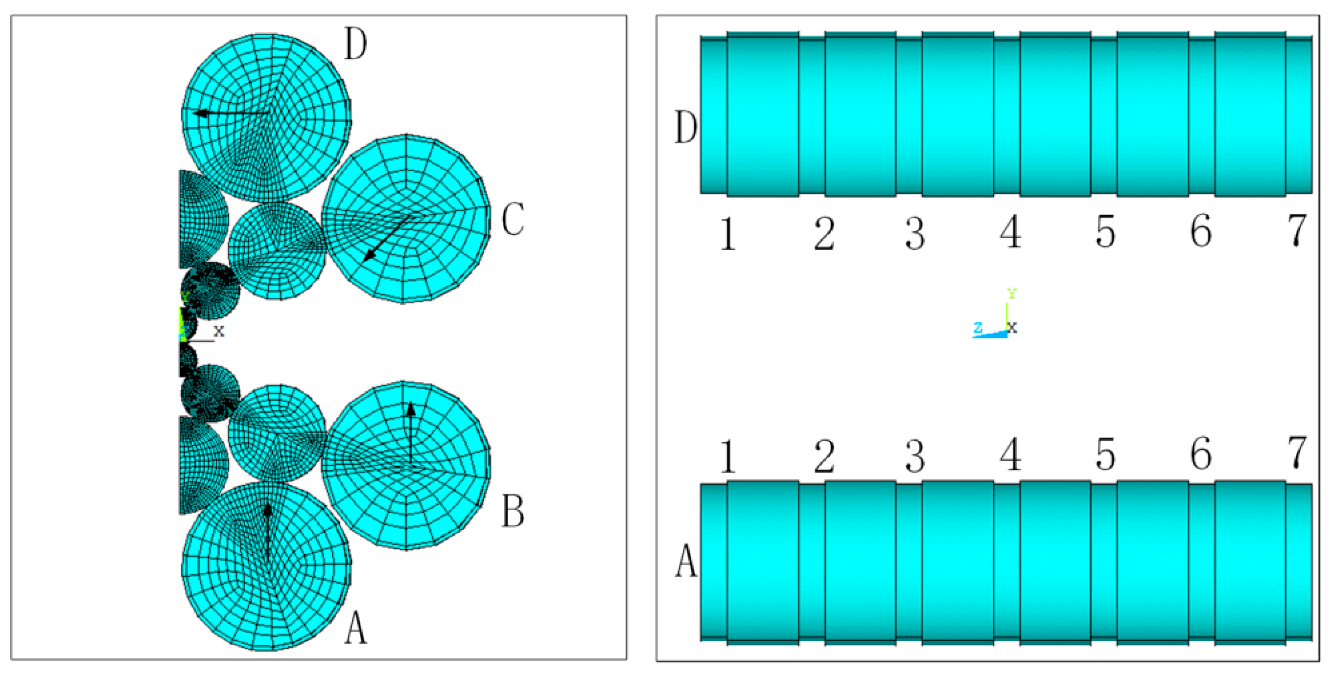
According to the actual rolling conditions of the rolling mill and the characteristics of the rolling process, the following displacement constraints were imposed on the finite element model: Symmetrical constraints were added on the symmetry planes; In addition, axial displacement constraints were applied to all nodes of the rolls, as well as to the central plane of the silicon strip, to prevent axial rigid body movement. Coupling constraints were added onto all nodes of the end face of the silicon strip along the rolling direction. The displacement loadings of A, B, C, and D backup rolls were applied to the corresponding nodes, and each backup roll had seven segments that could realize eccentricity in the range of 0 to 1.75 mm, as shown in Figure 2. The displacement loadings of A and B backup rolls were applied to achieve the reduction function for the thickness control; the displacement loadings of C and D backup rolls were applied to determine the ASU adjustment function.
2.2. Dynamics Model of the Rolling Process
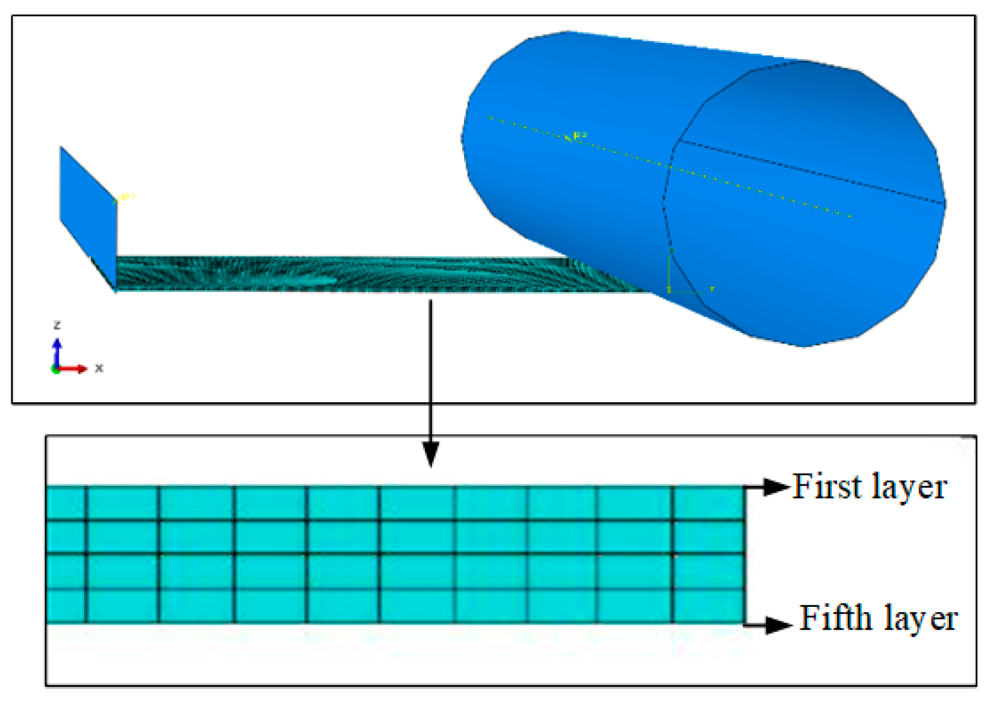
The dynamics model of the silicon strip rolling process was established by using the common finite element software ABAQUS (ABAQUS 6.14, Dassault Systemes, Providence, RI, USA). The work roll was defined as a rigid roll in the model. Considering the symmetry, only a quarter silicon strip was used in the model, and the SOLID186 element was used to divide the silicon strip. Finally, there were five layer nodes along the thickness direction, and a total of 39,600 elements and 51,615 nodes, as shown in Figure 3. The friction between the work roll and the strip was also the Coulomb friction. The dynamics model took the roll gap contour of the statics model as the initial roll contour to simulate the rolling process of silicon strip. First, the rolling strip was contacted with the roll by the action of the push plate, then, it was bitten into the roll gap to complete the rolling process under the action of the friction force and the entrance and exit tensions.
2.3. Verification of the Finite Element Model
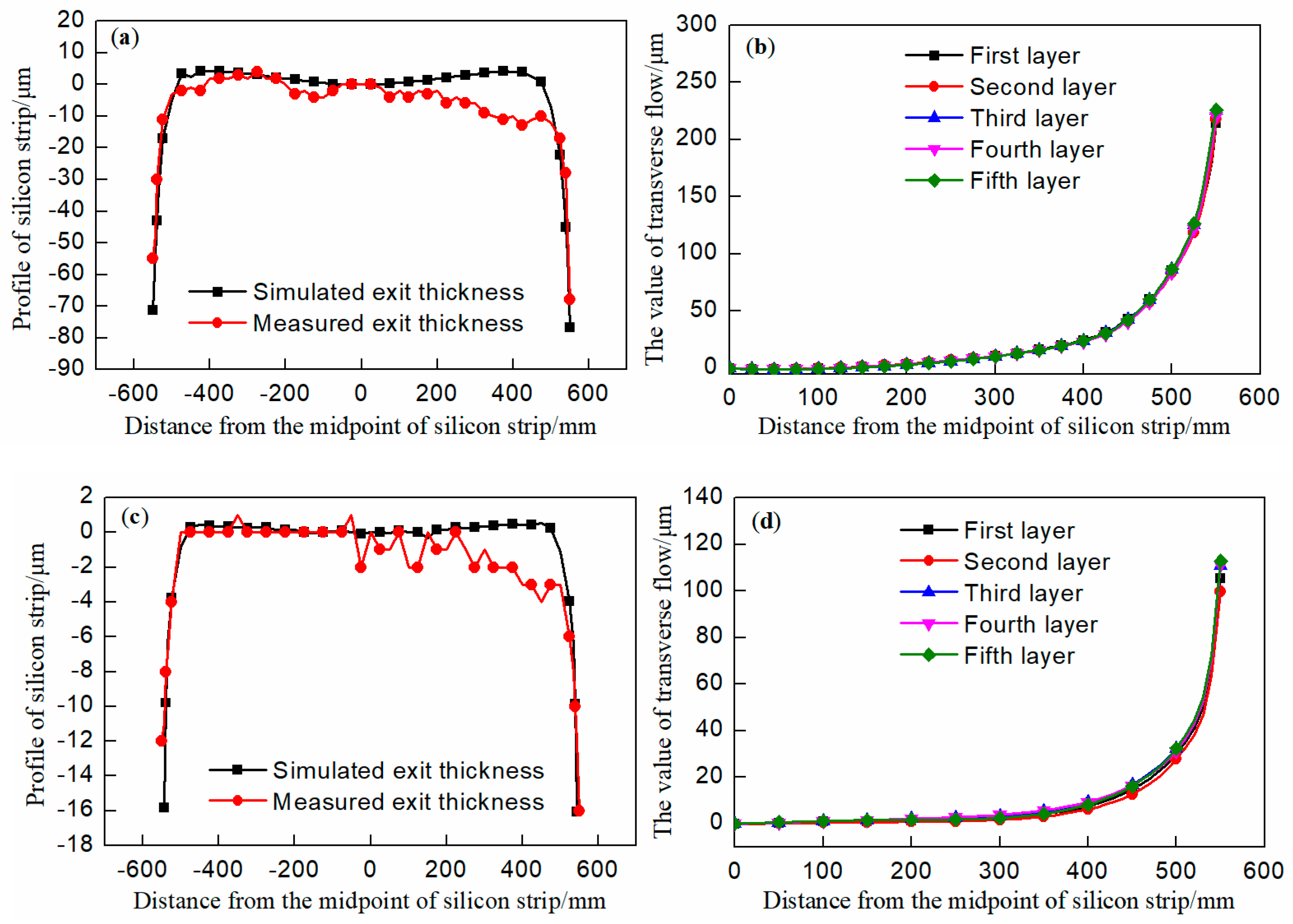
In order to more accurately verify the feasibility of the finite element model, the parameters of the first pass and fifth pass of the actual rolling process, whose entrance thickness, rolling reduction, work roll diameter, etc. are different, were taken as the input condition of the model. At the same time, the roll gap contour was extracted from the statics model and used as the initial roll contour of the dynamics model to calculate the actual rolling process of silicon strip, considering the transverse flow of metal. Finally, the simulation values of the strip exit profile and the values of metal transverse flow at nodes of each layer were obtained along a certain width direction, as shown in Figure 4. Comparing the simulated exit profile with the actual rolling exit profile (as shown in Figure 4a,c) along the strip width direction, it was seen that the profiles were basically consistent, and that the values of metal transverse flow were almost the same (as shown in Figure 4b,d). Therefore, the method for calculating the edge drop by the finite element models was reliable, which lays the foundation for subsequent analysis of silicon strip edge drop.
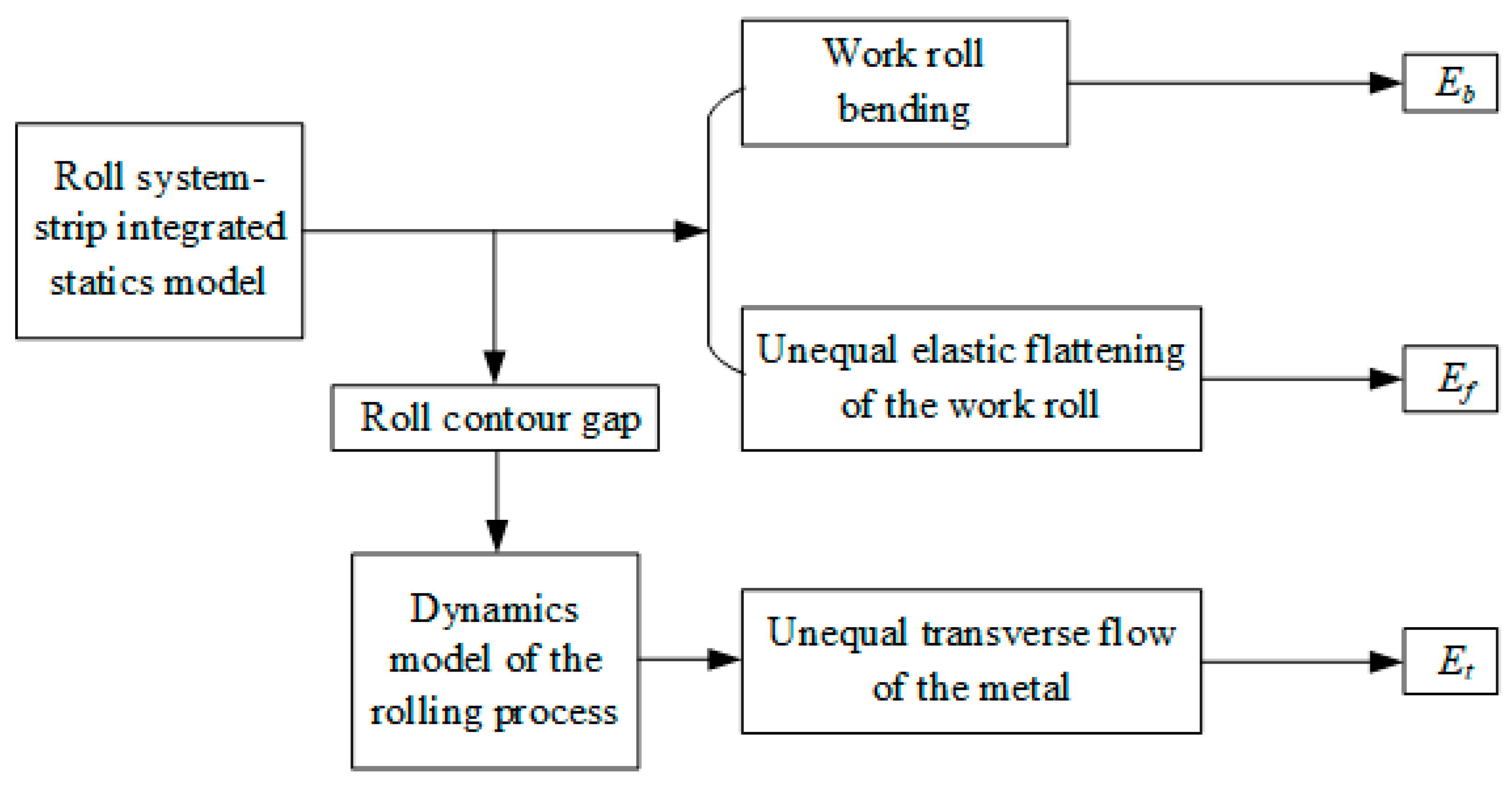
3. The Composition of Edge Drop for Silicon Strip
The edge drop of the silicon strip was mainly caused by the bending of the work roll, the unequal flattening of the work roll, and the unequal transverse flow of the metal in the Sendzimir mill [14,15]. Considering the unavoidable thickness drop, due to different factors in the actual rolling process, the edge drop was defined as the deviation between the thickness of 100 mm and 5 mm from the edge, which is described as Ed. The finite element model was used to calculate the edge drop based on the condition in the production to characterize the compositions of the edge drop for the silicon strip. In order to conveniently describe the edge drop caused by work roll bending, the unequal elastic flattening of the work roll and the unequal transverse flow of the metal are expressed as Eb, Ef, and Et, respectively. The compositions of silicon strip edge drop Eb, Ef, and Et, can be calculated according to Figure 5.
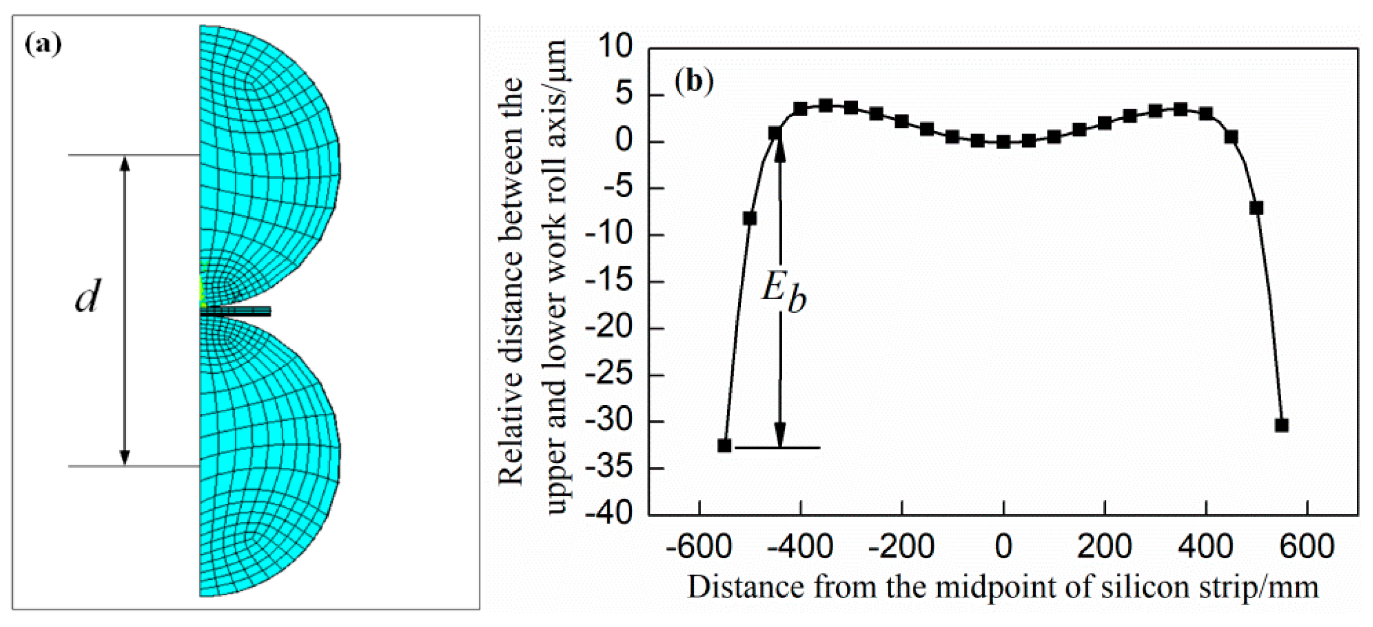
3.1. Edge Drop for Work Roll Bending
The edge drop Eb can be determined by the change of the relative position of the central axis of the work rolls. The distance of the central axis between the upper and lower work rolls along the roll body direction is defined as d (as shown in Figure 6a), and the edge drop Eb caused by the work roll bending is further shown in Equation (1). The Eb mainly results from two aspects: On the one hand, it is caused by the harmful contact zone within the contact range of the work roll and the first intermediate roll. In particular, because the contact length of the first intermediate roll and the work roll exceeds the width of silicon strip, the contact pressure of the extra length acts on the work roll to cause flexural deformation. On the other hand, the deformation of the rolls above the work roll forces it to deform correspondingly. The coordinates of each node of the upper and lower work roll axis were extracted from the finite element calculation results, and the relative values of the distance of central axis between each node in the upper and lower work rolls along the direction of the roll body were calculated, as shown in Figure 6b.
where the d1 is the distance between the axis of the upper and lower work rolls at 100 mm from the strip edge; d2 is the distance between the axis of the upper and lower work rolls at 5 mm from the strip edge.
Eb = d1 − d2
3.2. Edge Drop for the Unequal Elastic Flattening of the Work Roll
The edge drop Ef can be calculated by the inconsistent flattening of the work roll of the silicon strip along the width direction. The flattening values of the work roll along the roll body direction are defined as δ (as shown in Figure 7a), and the edge drop Ef caused by the unequal elastic flattening is further shown in Equation (2). The main reason for the edge drop Ef is that the rolling pressure, which acts on the work roll, is not equal along the width of the silicon strip. Due to the presence of the free end surfaces on both sides, the rolling pressure acting on the edge of the work roll is smaller than that in the middle of the work roll along the width direction when the strip is plastically deformed. Thus, the values of flattening on both sides are smaller than in the middle of the work roll, which results in the edge drop of the silicon strip. The coordinates of each node of the upper and lower work rolls, which are in contact with the strip, are extracted from the results of the finite element calculation, and the relative values of the distance between each node in the upper and lower work rolls are calculated along the direction of the roll body, as shown in Figure 7b.
where the δ1 is the flattening value of the work roll 100 mm from the strip edge; δ2 is the flattening value of the work roll 5 mm from the strip edge.
Ef = 2 × (δ1 − δ2)
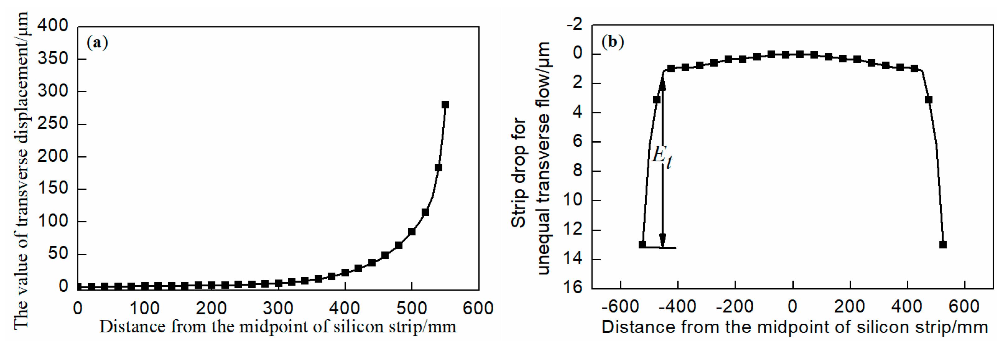
3.3. Edge Drop for the Unequal Transverse Flow of the Metal
The edge drop Et cannot be directly calculated from the finite element. The method is as follows: If there is no transverse flow of the metal during the rolling process, the strip thickness is the same along the width. If the metal flow is unequal, as shown in Figure 8a, it can result in unequal thickness reduction of the strip at any position along the width direction. Based on the principle of the metal volume invariance during the rolling process, the transverse thickness deviation at any position along the width direction is calculated, as shown in Figure 8b, and the calculation method of Ex and Et is shown in Equations (3) and (4). The main reason for the edge drop Et is that the flow principles of the metal are obviously different along the width direction of the strip in the rolling process. The farther the distance from the midpoint of the strip is, the smaller the flow resistance of the metal is, which makes the transverse displacement of the metal more obvious. The transverse flow resistance of the outermost point is almost zero. Therefore, in the edge region of the silicon strip, in addition to the longitudinal flow of the metal, traverse flow obviously occurs, which results in the edge drop of the silicon strip.
where x is the distance from the midpoint of silicon strip along the width direction; Ex is the transverse thickness deviation at any point along the strip width; Hx is the exit thickness with no transverse flow; hx is the exit thickness under the unequal transverse flow; k is the deviation coefficient in the calculation; θx is the value of the transverse displacement at any point along the strip width.
4. Results and Discussion
According to the forming mechanism of the edge drop, all factors that affect the rolling pressure and the transverse flow of the metal will affect the rolling pressure distribution and the work roll flattening directly, which inevitably affects the edge drop of the strip. During the process of the rolling silicon strip in the Sendzimir mill, different process parameters and roll contour configurations have different effects on the composition of silicon strip edge drop. By analyzing the influence of these factors, a theoretical basis is obtained to provide an effective means and effective strategies for controlling edge drop.
4.1. The Effect of Process Parameters on Edge Drop
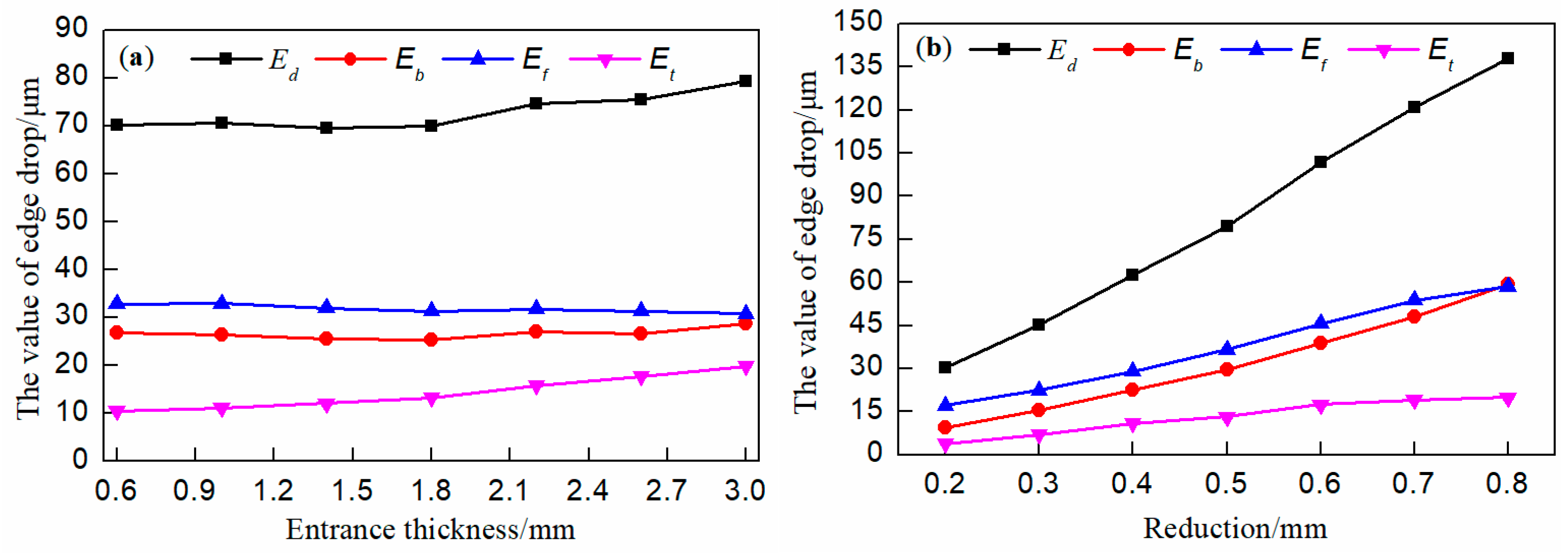
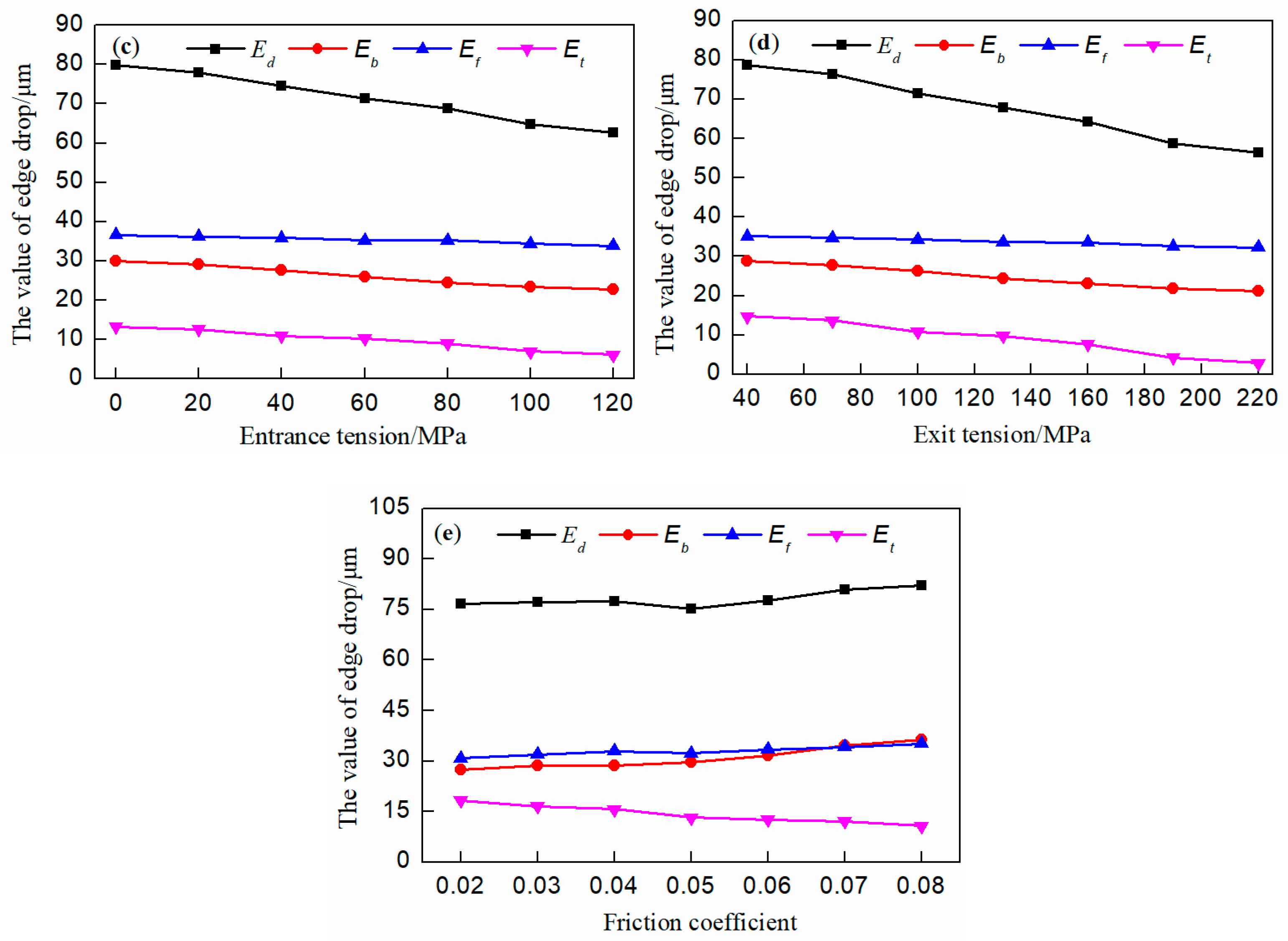
Combining the finite element model and the analysis of the composition of edge drop for the silicon strip, the effects of different process parameters, such as the entrance thickness, the rolling reduction, the entrance and exit tensions, and the friction coefficient on the edge drop were calculated, as shown in Figure 9.
It can be seen in Figure 9a that the Ed increased slightly with increasing entrance thickness, and in the composition of edge drop for silicon strip, Et increased significantly. The reason for this was that when the entrance thickness increases, the metal is relatively easy to deform, and the area of the free-end surfaces on both sides is also relatively large, which makes the silicon strip more susceptible to the occurrence of transverse flow.
It can be seen in Figure 9b that with increasing rolling reduction, the Ed increased steeply, in which the Eb and Ef increased more steeply than Et. When the rolling reduction increases, on the one hand, the rolling pressure increases; on the other hand, the silicon strip is more susceptible to the occurrence of transverse flow. However, during the rolling process in actual production, the distributions of the rolling reduction and the entrance thickness are basically fixed at each pass for the same specification silicon strip, which makes it difficult to effectively control the edge drop by adjusting the entrance thickness and the rolling reduction.
It can be seen in Figure 9c,d that as the entrance tension and the exit tension increased, the silicon strip edge drop Ed decreased slightly, while the Et decreased significantly, followed by Eb and Ef. According to the principle of minimum resistance, with the entrance and exit tensions increasing, the resistance that prevents the deformed metal from moving to the rolling direction decreases; thereby, the transverse flow of the silicon strip is suppressed. On the other hand, with the tension increasing, the rolling pressure decreases, which ultimately results in a corresponding decrease of Eb. However, in order to consider the stability of the rolling process, in actual production, the increases of the entrance tension and the exit tension are limited; thus their abilities to control the edge drop are limited.
As can be seen from Figure 9e, with increasing friction coefficient, the silicon strip edge drop Ed increased very slightly. In the composition of edge drop for the silicon strip, Eb and Ef increased, and the Et decreased. When the friction coefficient increased, on the one hand, the transverse flow of the metal was hindered. However, on the other hand, the rolling pressure increased. Finally, it can be seen that the change of the friction coefficient hardly controlled the edge drop.
4.2. The Effect of Roll Configuration on Edge Drop
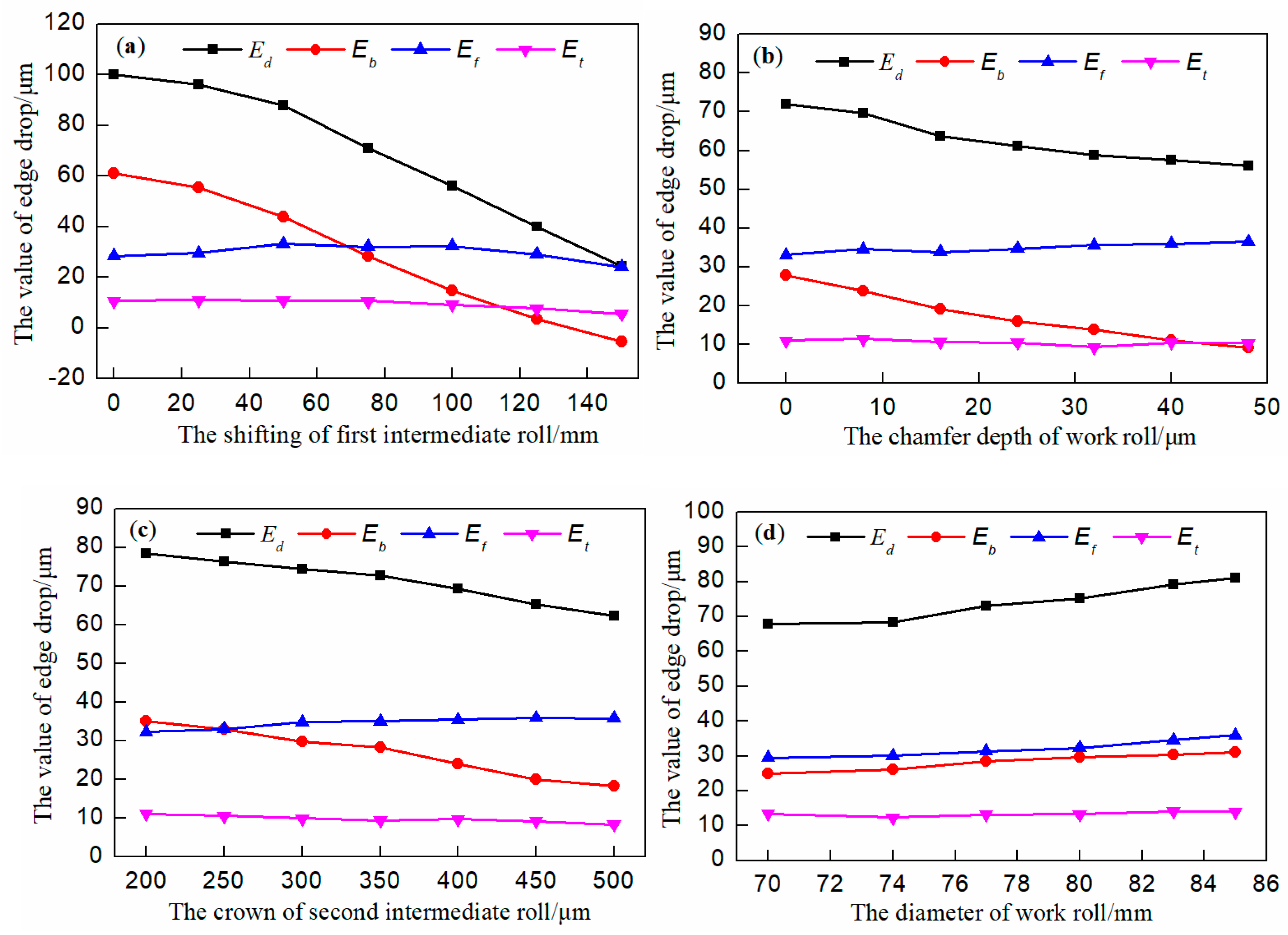
When the rolling mill is determined, the roll configuration is the most effective method to control the edge drop. Combined with the finite element model and the analysis of the composition of edge drop for silicon strip, the effect of the shifting of the first intermediate roll, the chamfer depth of the work roll, the crown of the second intermediate roll, and the diameter of the work roll on the edge drop are calculated. The results are shown in Figure 10.
It can be seen in Figure 10a,b that with increasing shifting of the first intermediate roll and the chamfer depth of the work roll, the edge drop Ed of silicon strip was steeply reduced, and in the compositions of edge drop for silicon strip, the Eb can be controlled effectively, but hardly had any influence on Ef and Et. The reason was that the shifting of the first intermediate roll and the chamfer depth of the work roll can effectively reduce the harmful contact area while compensating for the work roll bending. Therefore, it was known that the shifting of the first intermediate roll and the chamfer depth of the work roll could effectively control the silicon strip edge drop.
It can be seen in Figure 10c that with increasing crown of the second intermediate roll, the edge drop Ed decreased significantly. In the composition of the edge drop for the silicon strip, the Eb decreased steeply; however, it hardly had influence on the Ef and Et. The reason was that the crown of the second intermediate roll could compensate for the bending of the work roll. However, the excessive second intermediate roll crown was not favorable for the central flatness control of the silicon strip in actual production.
It can be seen in Figure 10d, that with an increasing diameter of the work roll, the edge drop Ed of the silicon strip increased slightly, while Eb, Ef and Et increased to varying degrees. The reason is that the contact area between the strip and the work roll increased when the diameter of the work roll increased, so that the rolling pressure increased, which eventually led to the increase of the bending of the work roll, and the unequal elastic flattening of the work roll. However, due to the very small allowable range of the work roll diameter, the control of the work roll diameter for the edge drop was also limited.
5. Conclusions
(1) The roll system and strip integrated statics model and the strip elastic-plastic deformation dynamics model of Sendzimir mill are established respectively. The statics model provides the roll gap contour for the dynamics model to take the transverse flow of the metal during the rolling process into account. The models are verified through the actual working conditions in the production. The accurate calculation of the exit profile and the transverse flow of silicon strip lay a foundation for the subsequent analysis of the edge drop.
(2) The edge drop of silicon strip is caused by the bending of the work roll, the unequal elastic flattening of the work roll, and the unequal transverse flow of the metal. Combined with the finite element models, the compositions of edge drop for the silicon strip are calculated.
(3) The study of the influence of different process parameters and the roll configuration on the edge drop shows that the entrance thickness, the rolling reduction, the entrance tension, and the exit tension, the friction coefficient, the crown of the second intermediate roll, and the diameter of work roll have limited control for the edge drop; the shifting of the first intermediate roll and the chamfer depth of the work roll have obvious effects on the edge drop by compensating the work roll bending. The research results provide theoretical guidance for the control of silicon strip edge drop in a Sendzimir mill.
Author Contributions
Z.Z., D.D. and G.H. did the former analysis and wrote the paper; H.L., J.Z. participated in the discussion on the results and guided the writing of the article; H.L. and X.Y. provided the dates in the production.
Funding
This research received no external funding.
Acknowledgments
This research was funded by “the National Key Technology R&D Program of the 12th Five-year Plan of China” (Grant number. 2015BAF30B01) and “the Fundamental Research Funds For the central Universities” (Grant numbers. FRF-BR-16-025A, FRF-TP-15-016A3).
Conflicts of Interest
The authors declare no conflict of interest.
References
- He, A.R.; Shao, J.; Sun, W.Q.; Guan, C.L.; Sheng, X.Y.; Zhang, J.P. Transverse Thickness Deviation Control of Non-oriented Silicon Steel during Cold Rolling. Chin. J. Mech. Eng. 2011, 47, 25–30. [Google Scholar] [CrossRef]
- Abdulrahman, A.; Jiang, Z.Y.; Wang, D.B.; Wang, X.D.; Hasan, T. Thin strip profile control capability of roll crossing and shifting in cold rolling mill. Mater. Sci. Forum 2013, 773–774, 70–78. [Google Scholar] [CrossRef]
- Hartung, H.G.; Hollmann, F.W. EDC—A new system for reduction of edge drop in cold rolling. Metall. Plant Technol. Int. 1998, 22, 80–82. [Google Scholar]
- Kitamura, K.; Nakanishi, T.; Yarita, I.; Suganuma, N.; Toyoshima, K. Edge-drop control of hot and cold rolled strip by tapered-crown work roll shifting mill. Iron Steel Eng. 1995, 72, 27–32. [Google Scholar]
- Cao, J.G.; Qi, J.B.; Zhang, J.; Wang, C.; Zeng, W.; Gong, G.L. Backup roll contour for edge drop control technology in tandem cold rolling mill. J. Cent. South Univ. 2008, 39, 1011–1016. [Google Scholar]
- Berger, B.; Schulte, H.; Benfer, M.; Rinke, F.W. Advanced 20-high mill technology. Metall. Plant Technol. Int. 2000, 23, 70–72. [Google Scholar]
- Sun, W.Q.; Yang, Q.; Shao, J.; He, A.R.; Li, M.X. Edge drop control technique of silicon steel for UCM tandem cold rolling mills. J. Univ. Sci. Technol. Beijing 2010, 32, 1340–1345. [Google Scholar] [CrossRef]
- Abdelkhalek, S.; Montmitonnet, P.; Legrand, N.; Buessler, P. Coupled approach for flatness prediction in cold rolling of thin strip. Int. J. Mech. Sci. 2011, 53, 661–675. [Google Scholar] [CrossRef]
- Hartung, H.G.; Hollmann, F.W.; Holz, R.; Richter, H.P. New way to reduce the edge drop. Steel Res. 1998, 69, 143–147. [Google Scholar] [CrossRef]
- Jin, Q.; Wang, W.; Jiang, R.; Chiu, L.N.S.; Liu, D.; Yan, W. A Numerical Study on Contact Condition and Wear of Roller in Cold Rolling. Metals 2017, 7, 376. [Google Scholar] [CrossRef]
- Zheng, H.P. Research on edge drop control by double taper work roll of cold rolling mill. Steel Rolling 2012, 29, 11–12. [Google Scholar] [CrossRef]
- Liu, C.; He, A.R.; Qiang, Y.; Guo, D.F.; Shao, J. Effect of Internal Stress of Incoming Strip on Hot Rolling Deformation Based on Finite Element and Infinite Element Coupling Method. Metals 2018, 8, 92. [Google Scholar] [CrossRef]
- Cao, J.G.; Chai, X.T.; Li, Y.L.; Kong, N.; Jia, S.H.; Zeng, W. Integrated design of roll contours for strip edge drop and crown control in tandem cold rolling mills. J. Mater. Process. Technol. 2017, 252, 432–439. [Google Scholar] [CrossRef]
- Chang, A.; Di, H.S.; Bai, J.L.; Dong, Q.; Yang, D.J. Effect of Rolling Parameters on Edge-Drop in Cold Rolling. Iron Steel 2007, 42, 51–56. [Google Scholar] [CrossRef]
- Lu, H.T.; Cao, J.G.; Zhang, J.; Zeng, J.S.; Zeng, W.; Qin, S.G. Edge drop control of a taper roll during cont inuous cold rolling. J. Univ. Sci. Technol. Beijing 2006, 28, 774–777. [Google Scholar] [CrossRef]
- Xuan, K.L.; Yu, W.; Tang, W.; Xiong, A.M.; Zhang, X.F.; Ren, X.Y. Simulation study of strip edge control performance of six-high cold rolling mill. Steel Rolling 2017, 34, 33–37. [Google Scholar] [CrossRef]
- Malik, A.S.; Grandhi, R.V. A computational method to predict strip profile in rolling mills. J. Mater. Process. Technol. 2008, 206, 263–274. [Google Scholar] [CrossRef]
- Yu, H.L.; Liu, X.H.; Lee, G.T.; Prak, H.D. Numerical analysis of strip edge drop for Sendzimir mill. J. Mater. Process. Technol. 2008, 208, 42–52. [Google Scholar] [CrossRef]
- Hamada, R.; Yoshida, K.; Kurita, A.; Hara, K. Improvement of Strip Flatness in 20-High Sendzimir Mill by means of Numerical Simulation. In Proceedings of the 10th ICSR, Beijing, China, 15–17 September 2010; Volume 5. [Google Scholar]
- Zhang, Q.D.; Dai, C.; Wen, J.; Zhang, X.F.; Qin, J. Simulation and Analysis on Shape Control Behavior of 20-h Sendzimir Mill. Steel Rolling 2013, 30, 1–6. [Google Scholar] [CrossRef]
- Liu, Y.F.; Huang, Y.; Zhao, X.H.; Sun, Y.B.; Yan, D. Analysis on characteristics of traversing influence of the first intermediate roll in Sendzimir twenty-roller Mill. Heavy Mach. 2013, 2–6. [Google Scholar] [CrossRef]
- Cho, J.H.; Hwang, S.M. A New Model for the Prediction of Roll Deformation in a 20-High Sendzimir Mill. J. Manuf. Sci. Eng. 2014, 136, 011004. [Google Scholar] [CrossRef]
- Yuan, Z.W.; Ren, Z.K.; Xiao, H.; Yu, C. Plate shape control of ultra thin strip rolling for 20-high mill. J. Cent. South Univ. 2017, 48, 860–866. [Google Scholar]
- Li, C.W.; Wang, X.C.; Yang, Q.; Wang, L.S. Metal Transvers flow and its influence factors of hot rolled strips. J. Univ. Sci. Technol. Beijing 2013, 35, 222–227. [Google Scholar] [CrossRef]
Figure 1.
Roll system and strip-integrated statics model.

Figure 2.
The diagram of the backup roll.

Figure 3.
Dynamics model of the rolling process.

Figure 4.
Verification of the finite element models: (a) The exit profile of the first pass; and (b) the metal transverse flow of the first pass; (c) the exit profile of the fifth pass; and (d) the metal transverse flow of the fifth pass.
Figure 4.
Verification of the finite element models: (a) The exit profile of the first pass; and (b) the metal transverse flow of the first pass; (c) the exit profile of the fifth pass; and (d) the metal transverse flow of the fifth pass.

Figure 5.
The method of calculating the edge drop Eb, Ef, and Et.

Figure 6.
The edge drop for work roll bending: (a) Distance at any point between the upper and lower work roll axis; and (b) finite element calculation results.
Figure 6.
The edge drop for work roll bending: (a) Distance at any point between the upper and lower work roll axis; and (b) finite element calculation results.

Figure 7.
The edge drop for the unequal flattening of the work roll: (a) Value of flattening at any point of the work roll; and (b) finite element calculation results.
Figure 7.
The edge drop for the unequal flattening of the work roll: (a) Value of flattening at any point of the work roll; and (b) finite element calculation results.

Figure 8.
The edge drop for the unequal transverse flow of the metal: (a) Value of transverse displacement at any point of the metal; and (b) finite element calculation results.
Figure 8.
The edge drop for the unequal transverse flow of the metal: (a) Value of transverse displacement at any point of the metal; and (b) finite element calculation results.

Figure 9.
The effect of process parameters on edge drop: (a) Entrance thickness; (b) rolling reduction; (c) entrance tension; (d) exit tension; and (e) friction coefficient.
Figure 9.
The effect of process parameters on edge drop: (a) Entrance thickness; (b) rolling reduction; (c) entrance tension; (d) exit tension; and (e) friction coefficient.


Figure 10.
The effect of roll contour configuration on edge drop: (a) The shifting of the first intermediate roll; (b) the chamfer depth of the work roll; and (c) the crown of the second intermediate roll; (d) the diameter of the work roll.
Figure 10.
The effect of roll contour configuration on edge drop: (a) The shifting of the first intermediate roll; (b) the chamfer depth of the work roll; and (c) the crown of the second intermediate roll; (d) the diameter of the work roll.


Table 1.
Key parameters for the finite element model.
| Parameter Type | Value |
|---|---|
| Work roll diameter × roll length (mm × mm) | Φ 80 × 1677 |
| The first intermediate roll diameter × roll length (mm × mm) | Φ 138 × 1500 |
| The second intermediate roll diameter × roll length (mm × mm) | Φ 234 × 1450 |
| Backup roll diameter × roll length (mm × mm) | Φ 405 × 1417 |
| Roll elastic modulus/GPa | 210 |
| Roll Poisson ratio | 0.3 |
| Silicon strip width/mm | 1100 |
| Silicon elastic modulus/GPa | 220 |
| Silicon Poisson ratio | 0.3 |
| Friction coefficient | 0.05 |
© 2018 by the authors. Licensee MDPI, Basel, Switzerland. This article is an open access article distributed under the terms and conditions of the Creative Commons Attribution (CC BY) license (http://creativecommons.org/licenses/by/4.0/).
Share and Cite
MDPI and ACS Style
Li, H.; Zhao, Z.; Dong, D.; Han, G.; Zhang, J.; Liu, H.; You, X. Edge-Drop Control Behavior for Silicon Strip Cold Rolling with a Sendzimir Mill. Metals 2018, 8, 783. https://doi.org/10.3390/met8100783
AMA Style
Li H, Zhao Z, Dong D, Han G, Zhang J, Liu H, You X. Edge-Drop Control Behavior for Silicon Strip Cold Rolling with a Sendzimir Mill. Metals. 2018; 8(10):783. https://doi.org/10.3390/met8100783
Chicago/Turabian StyleLi, Hongbo, Zhenwei Zhao, Dawei Dong, Guomin Han, Jie Zhang, Haichao Liu, and Xuechang You. 2018. "Edge-Drop Control Behavior for Silicon Strip Cold Rolling with a Sendzimir Mill" Metals 8, no. 10: 783. https://doi.org/10.3390/met8100783
Note that from the first issue of 2016, this journal uses article numbers instead of page numbers. See further details here.