Article

Residual Stress, Mechanical Properties, and Grain Morphology of Ti-6Al-4V Alloy Produced by Ultrasonic Impact Treatment Assisted Wire and Arc Additive Manufacturing

School of Mechanical and Vehicular Engineering, Beijing Institute of Technology, Beijing 100081, China
*
Author to whom correspondence should be addressed.
Metals 2018, 8(11), 934; https://doi.org/10.3390/met8110934
Submission received: 9 October 2018 / Revised: 8 November 2018 / Accepted: 9 November 2018 / Published: 12 November 2018
(This article belongs to the Special Issue Additive Layer Manufacturing using Metal Deposition)

Abstract

:
Ultrasonic Impact Treatment (UIT) is an effective technique for surface refinement and residual stress reduction, which is widely used in welding. This study investigates UIT-assisted Wire and Arc Additive manufacturing (WAAM). The residual stress, grain morphology and mechanical properties of post-UIT and as-deposited samples are studied. The result demonstrates that the UIT has a significant influence on the decrease of the residual stress. Moreover, the residual stress of the post-UIT samples is much lower than that of the as-deposited samples. The samples fabricated by UIT-assisted WAAM have a novel, bamboo-like distribution of prior-β grains, an alternating distribution of short columnar grains and equiaxed grains. The grain size of this bamboo-like structure is much smaller than the coarsen columnar grains. In addition, the mechanical properties of the post-UIT and as-deposited samples are compared. The results indicate that the average tensile strength of the post-UIT samples is higher, while the average elongation of the post-UIT samples is lower.

1. Introduction

Over the past 30 years, additive manufacturing (AM) has gained increasing attention in the aerospace, automotive, and rapid-tooling industries, especially in the production of model parts and prototypes, due to its superiority in big scale and complex-shaped metal component fabrication [1,2,3,4]. WAAM is a promising alternative to traditional subtractive manufacturing for fabricating large expensive parts because of its low buy-to-fly ratio and high deposition rate. As one of the most important aerospace alloys, Ti-6Al-4V parts fabricated by WAAM have been widely investigated by many researchers [4,5,6,7].
However, there are some unsolved challenges associated with WAAM. For example, high residual stress is one of the major concerns. High residual stress is the source of numerous problems, including part distortion, low part tolerance, and premature failure. At present, researchers generally focus on two different strategies for residual stress reduction. One is to control the built-up residual stress during the deposition process. The other involves the use of post-processing technologies. The former strategy has been widely investigated. Fessler et al. determined that the selective deposition approach—which initially deposits a series of small patches, then subsequently joins them together to form a large patch—can decrease the residual stress compared to traditional integrated deposition methods [8]. Based on a combination of Finite element analysis and experimental investigation, Chin reported that uniform substrate preheating reduces residual stresses [9]. With respect to post-processing technologies, Colegrove et al. discovered that TC4 parts manufactured by WAAM can exhibit significant residual stress. However, high-pressure rolling, especially the use of a slotted roller on the WAAM parts, can reduce the residual stress [10]. In addition, the traditional method of Ultrasonic Impact Treatment (UIT) has been proved to be very useful in addressing the residual stress problem in welding. UIT is an effective technique for reducing residual stress and improving the fatigue performance of welded structures. Gao et al. applied UIT to the toe of welded joints, and determined that the fatigue life improved with a change in the weld geometry and the residual stress state [11]. Mordyuk et al. determined that UIT-treated specimens experience an increase in a microhardness and fatigue relative to annealed alloys, while the surface roughness of the former in terms of the stress concentration factor did not exceed ~10% [12]. The mechanism of UIT involves the creation of a severe surface plastic deformation via high frequency (close to 27,000 Hz) oscillation of an impact head [13]. Based on the distance from the surface, the influence area of UIT can be divided into 3 regions, as shown in Figure 1 [14]: (1) zone of grain refinement, (2) zone of plastic deformation, and (3) zone of stress relaxation. The most notable effect of the UIT technique is surface nanocrystallization and residual stress release [15].
Previous research has shown that UIT has a significant effect on the reduction of the residual stress of welded joints. Since the WAAM and TIG (Tungsten Inert Gas Welding) welds have a similar thermal process, a novel hybrid process of WAAM and UIT is proposed to fabricate Ti-6Al-4V parts. This study explores the fabrication of Ti-6Al-4V samples by the proposed WAAM and UIT process, and the results reveal improved grain size and reduced residual stress compared to WAAM only.

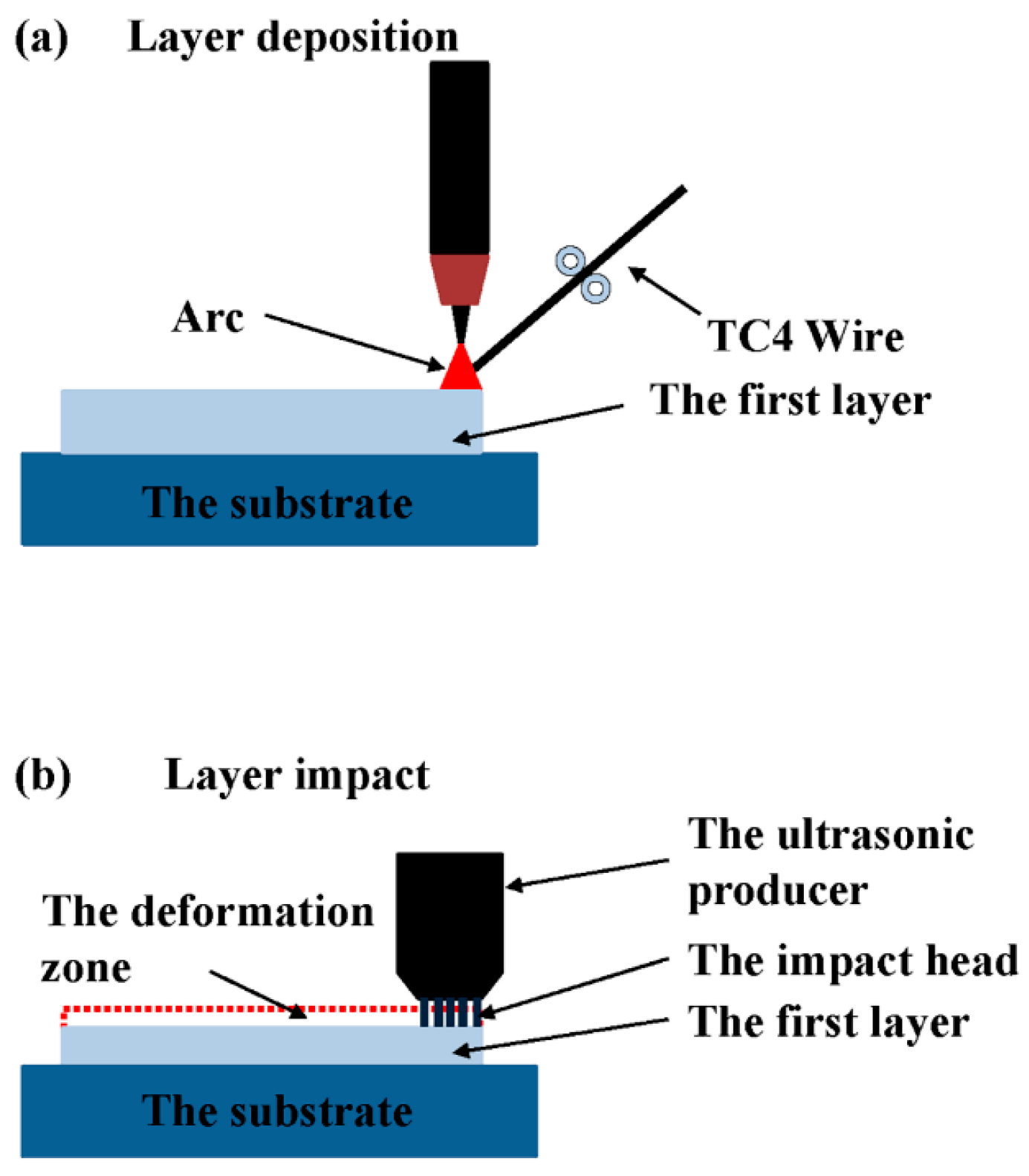
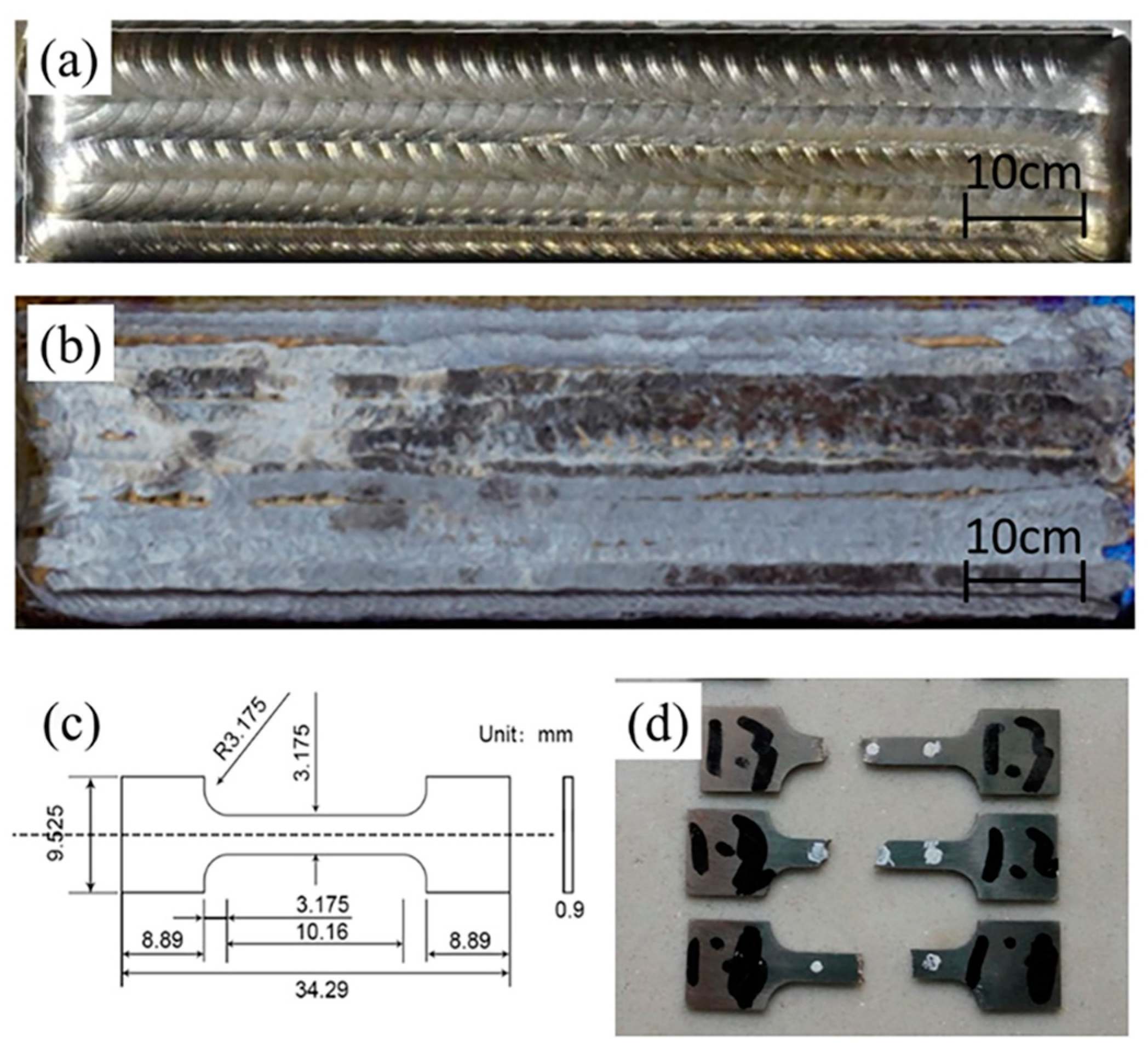
2. Materials and Methods

The experimental system consists of an automatic wire-feed arc additive manufacturing equipment and a UIT equipment (Huawin Hawking, Jinan, China). Figure 2a shows the integrated weld tungsten head and the UIT head, both operating in an inert atmosphere environment (Figure 2b). In addition, the parameters of the computer system and weld equipment responsible for determining the scanning path and the control of the welding process are shown in Table 1. The UIT output parameters are controlled by the UIT controller and the equipment consist of an ultrasonic transducer, an impact pin, and the controller. The head consists of the transducer and the impact pin, which are fixed with the welded tungsten head (Figure 1a). The ultrasonic transducer converts electric energy into mechanical energy in the form of high-frequency oscillations. The impact pin transmits the oscillations to the surface of the sample. The as-deposited surface and the post-UIT surface are shown in Figure 3a,b.
A novel hybrid process is used to fabricate Ti-6Al-4V parts. The fabrication of every layer consists of two steps. Firstly, a multi-track of material is deposited on the substrate, which is 150 × 150 mm2 and 15 mm thick. Secondly, UIT is applied twice to the deposited surface immediately after the deposition process. Four samples were fabricated, including two single-layer samples without or with the application of UIT, and two seven-layers samples without or with UIT application. For all samples, every layer was deposited using seven parallel hatches using a back-and-forth raster. For the post-UIT samples, after every layer was deposited, the UIT process with 21 back-and-forth parallel hatches was immediately performed a total of two times. The next layer was deposited directly after the UIT process of the previous layer was completed. This is a continual process which is regulated by a control system.
Metallographic specimens were prepared by a conventional mechanical polishing method. A mixture of 1 mL HF, 6 mL HNO3 and 100 mL H2O was used as the etching agent (Sinopharm Chemical Reagent Co., Ltd, Shanghai, China). The surface morphology and microstructures of the samples were characterized by optical microscopy (OM) (Olympus, Tokyo, Japan), and the β grain size was measured using metallographic image analysis software SISC IAS v8.0 (KYKY Technology, Bejing, China). Quantitative measurements were conducted on at least five OM micrographs with a magnification of 200× for each specimen. The residual stress at the top region was measured using the hole-drilling method of the Chinese national standard CB/T 3395-2013. The top region is defined as a region from the top surface to the hole bottom. The diameter of the hole is 1.5 mm and the depth is 2 mm. The residual stress is calculated according to the measured release of the strain during the drilling process. The tensile test was performed at the INSTRON-5966 (INSTRON, Boston, MA, USA) tensile test solution and the size of the test samples is shown in Figure 4c. Figure 4d shows the samples after tensile testing. The tensile test samples measured are taken perpendicular to the scanning direction from the deposition.

3. Results and Discussion

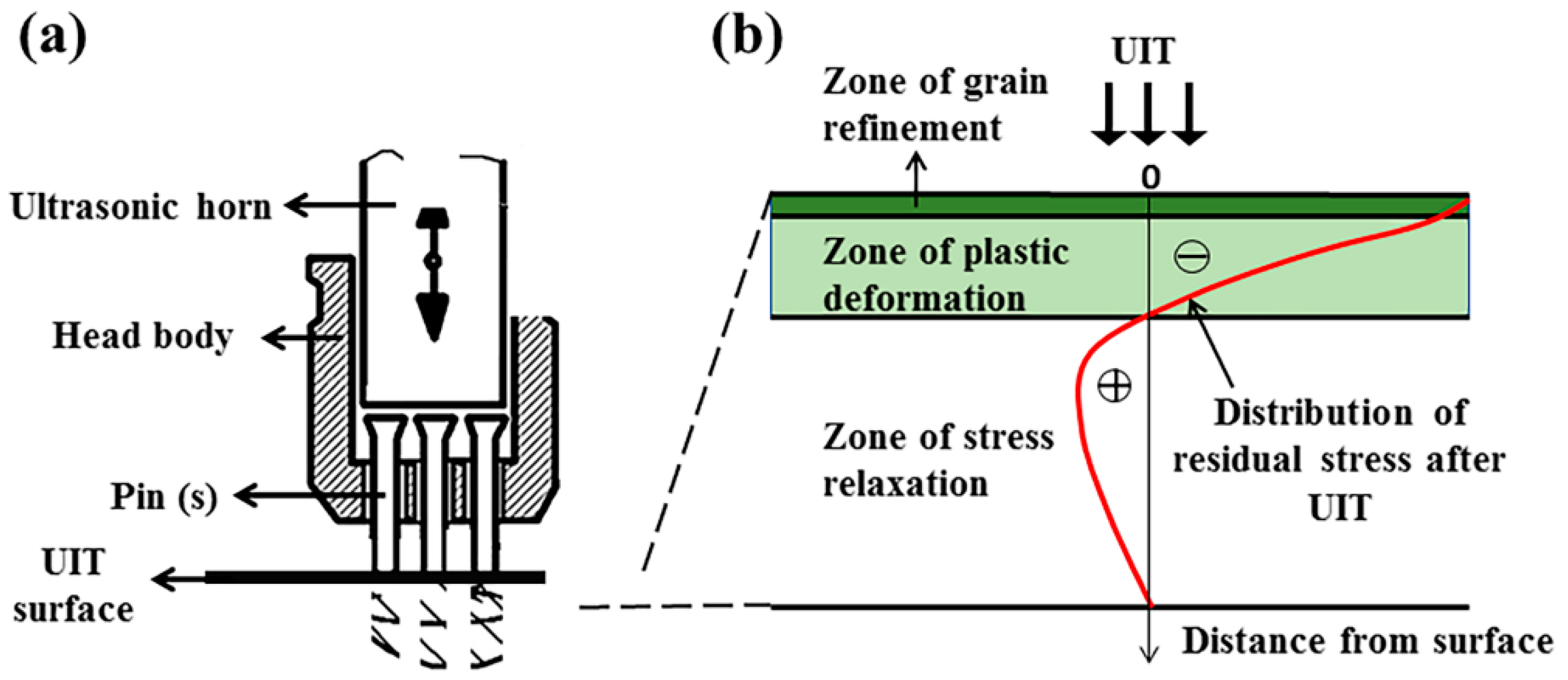
3.1. Residual Stress
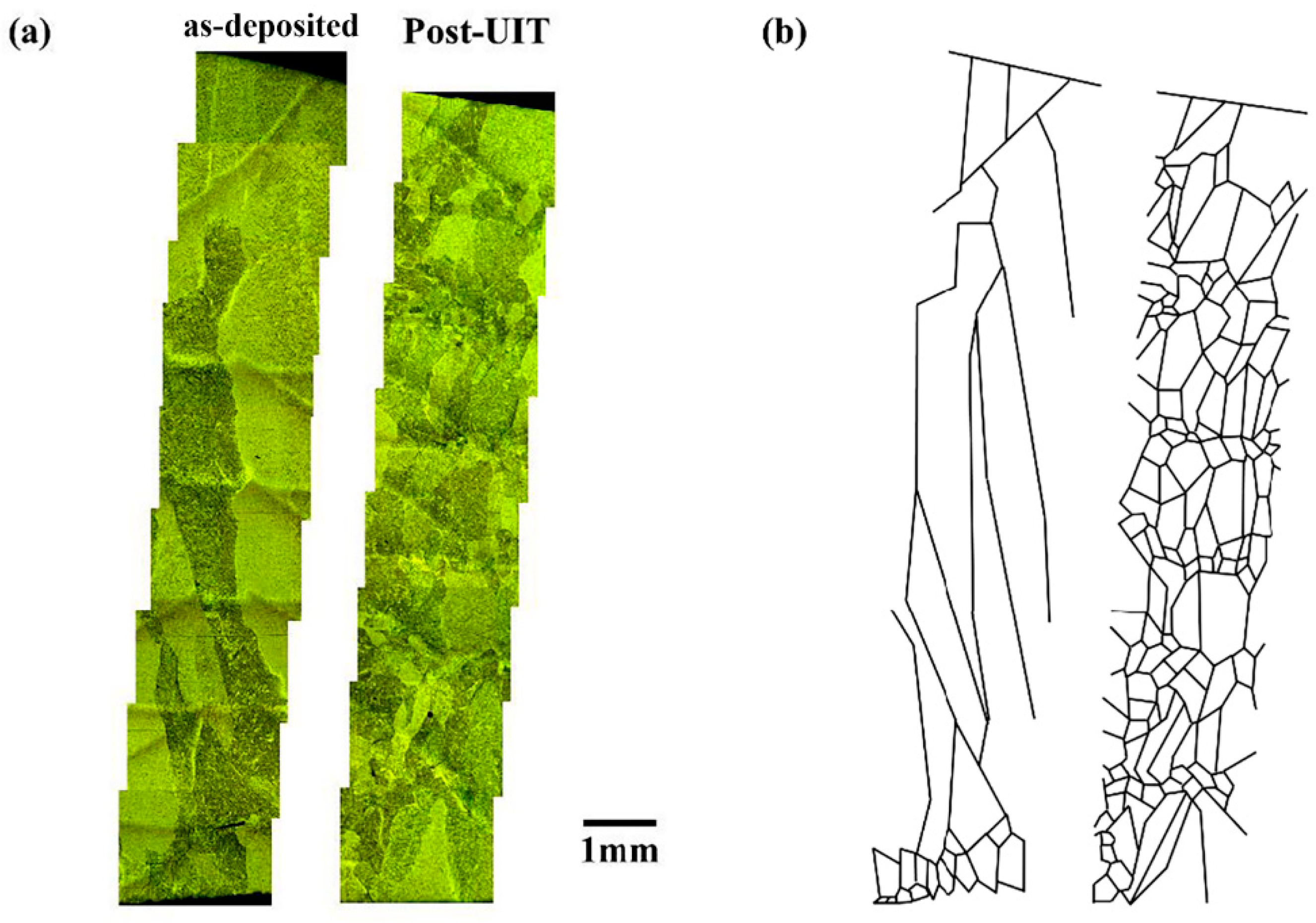
The four samples are made using the same parameters. The two single-layer samples and the other seven-layer samples are used for two group of controlled experiments, that compare the surface and grain differences for post-UIT and the as-deposited state. The results of the residual stress are shown in Table 2.
The results of the residual stress exhibit four key important features. Firstly, comparing the single-layer samples with the seven-layer samples for the same manufacturing process, the residual stress for the single layer as-deposited samples is much lower than that of the 7 layers samples. Secondly, the residual stress of the seven-layer samples without UIT is nearly three times that of the single-layer sample without UIT. Thirdly, the residual stress of the post-UIT samples decreases by about 43.0% compared to that of the as-deposited samples. Finally, the post-UIT samples exhibited very similar residual stress.
Both the single-layer and the seven-layer samples indicate that the UIT has a significant effect on the decrease of the residual stress, because severe plastic deformation of the surface via repetitive impacts with simultaneous compressive and shear modes with a high rate strain, as shown in Figure 4b, counteract the final tensile stress induced by the deposition process [16]. The result is a large drop in the residual stress between as-deposited and post-UIT samples. Moreover, the residual stress of the seven-layer samples shows a more significant change compared to that of the single-layer samples. The residual stress is induced by the unbalanced application of heat during the deposition process. The thermal circle of the single-layer results in tensile stress accumulation. With the increase in the number of deposited layers, the residual tensile stress will be higher in each succeeding layer compared to the last layer. However, the residual stress is almost the same for all the post-UIT samples. This can be explained by the fact that the effect of UIT serves to reduce the accumulation of residual stress of every layer.

3.2. Macrostructure

Figure 5a represents the macrostructure of the seven-layer samples from the bottom to the top. The as-deposited sample has common coarsen columnar β grains with an average size of 785 μm and a respect ratio of 3.42. The β grains are produced at the surface of the substrate, and grow through several layers, almost from the bottom to the top. In comparison with the as-deposited sample, the post-UIT sample has a pronounced refinement of the grain size and shape. The β grains of the post-UIT sample exhibited alternating short columnar grains and equiaxed grains. The average grain size of the short columnar and equiaxed grains are 371 μm and 186 μm respectively, and the grain respect ratio of both grains are 2.16 and 1.33, respectively. As Figure 5b shows, the colonies of columnar and equiaxed grain are alternatively distributed along the building direction. There are 6 colonies of the equiaxed grain (the surface of the top has no equiaxed grains). They distribute around the fusion lines which are located at the interface of two deposition layers. The short columnar grains are generated as a result of the recrystallization at the surface of every layer. The newly formed equiaxed grains cut off the big columnar β grains, forming a bamboo-like microstructure [17].
The refinement of the grain size can be explained by the interaction of the deposition and UIT processes. Figure 6 shows the mechanism of the refinement. The coarsen columnar grains associated with individual deposition process are attributed to the high and unidirectional temperature gradient, which is common in WAAM samples. The characteristics of the deposition process determine the maximal temperature gradient parallel to the deposition direction, which is called “epitaxial grain growth” [18,19,20,21], as shown in Figure 5.
For post-UIT samples, the UIT process induces a severe plastic deformation in the layers, which causes the height to be reduced compared to the corresponding layer of the as-deposited samples, as shown by the yellow range in Figure 5b. This deformation produces a huge number of dislocations in the post-UIT surface, and much energy is stored in the dislocation, which means that there is not enough for immediate recrystallization. The lack of equiaxed grains at the top surface of the post-UIT samples, as shown in Figure 5a, proved this assumption. When the next layer is deposited, the pulse arc heats and remelts the deformation surface of the previous layer. The dislocations in the deformation surface recrystallize when they are subjected to rapid heating. However, the energy of the pulse arc is not sufficient to remelt all the recrystallizing equiaxed grains, and there are still some residual equiaxed grains at the bottom of the colonies of grains, as indicated by the macrostructure of the post-UIT sample in Figure 5. In addition, with an incoming pulse arc, there is still epitaxial grains growth, but the newly-formed columnar grains grow from the top surface of the residual equiaxed grains instead of the short columnar grains of the previous layers, because of the presence of the equiaxed grains between the two layers. Finally, the post-UIT sample forms a bamboo-like morphology, with the colonies of the equiaxed grains and the short columnar grains distributing alternatively along the deposition direction.

3.3. Microstructure

The microstructure of both samples is martensitic α grain [22,23]. This is one of the common microstructures of TC4 fabricated by WAAM. The formation of martensitic α grain occurs because of the high cooling rate [24], as is shown in Figure 7a–c. Since the formation of the martensitic α grain is during the cooling process and the UIT process has little influence on this process, the post-UIT sample has the same microstructures as the as-deposited sample.

3.4. Mechanical Properties

As shown in Figure 8, the post-UIT samples (black curves) have a higher tensile strength than the as-deposited samples. The average tensile strength of the post-UIT samples is 934 MPa, while that of the as-deposited samples is 870 MPa. The grain size of the post-UIT samples is much smaller than that of the as-deposited samples thereby inducing an improvement in the tensile strength [22,25]. This increase occurs because the short columnar and equiaxed grains replace the coarser columnar grains. With regard to ductility, the post-UIT samples and the as-deposited samples exhibit no significant difference. The average elongation of both samples is 10.29% and 11.95%, respectively.

4. Conclusions

This study investigates the influence of the UIT on the residual stress, morphology, and mechanical strength of samples fabricated with WAAM. According to the results, the following conclusions can be drawn:
(1)
The residual stress is significantly reduced when UIT is applied. The single-layer post-UIT samples exhibited a 43% decrease compared to the WAAM samples, while the reduction for the seven-layer samples was much greater at 77.3%.
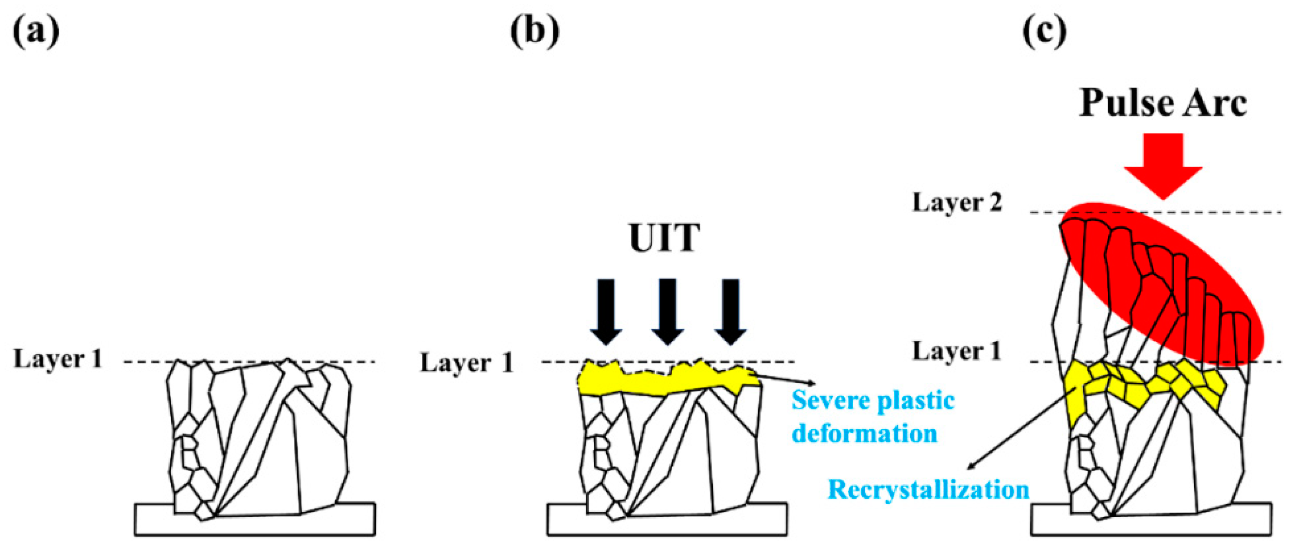
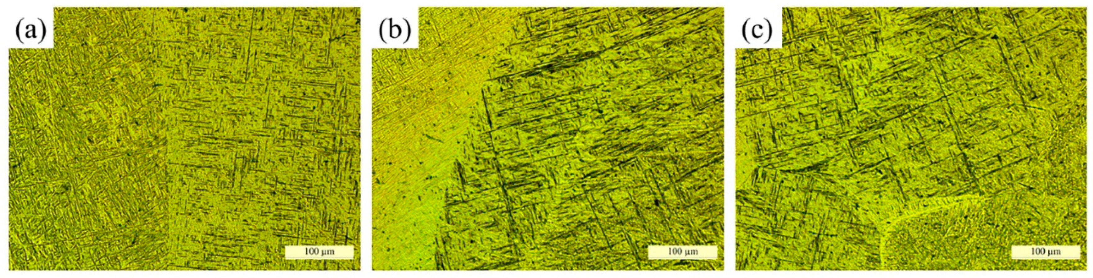
(2)
The macrostructure of prior-β grain changed from coarsen columnar β grain to an alternating distribution of equiaxed grain and short columnar grain, and formed a bamboo-like structure. The average grain size decreased from 785 μm to 371 μm, and the respect ratio of the β grain of the as-deposited samples and post-UIT samples are 3.42 and 2.16, respectively. The equiaxed grain size and respect ratio of the post-UIT samples are 186 μm and 1.33 μm.
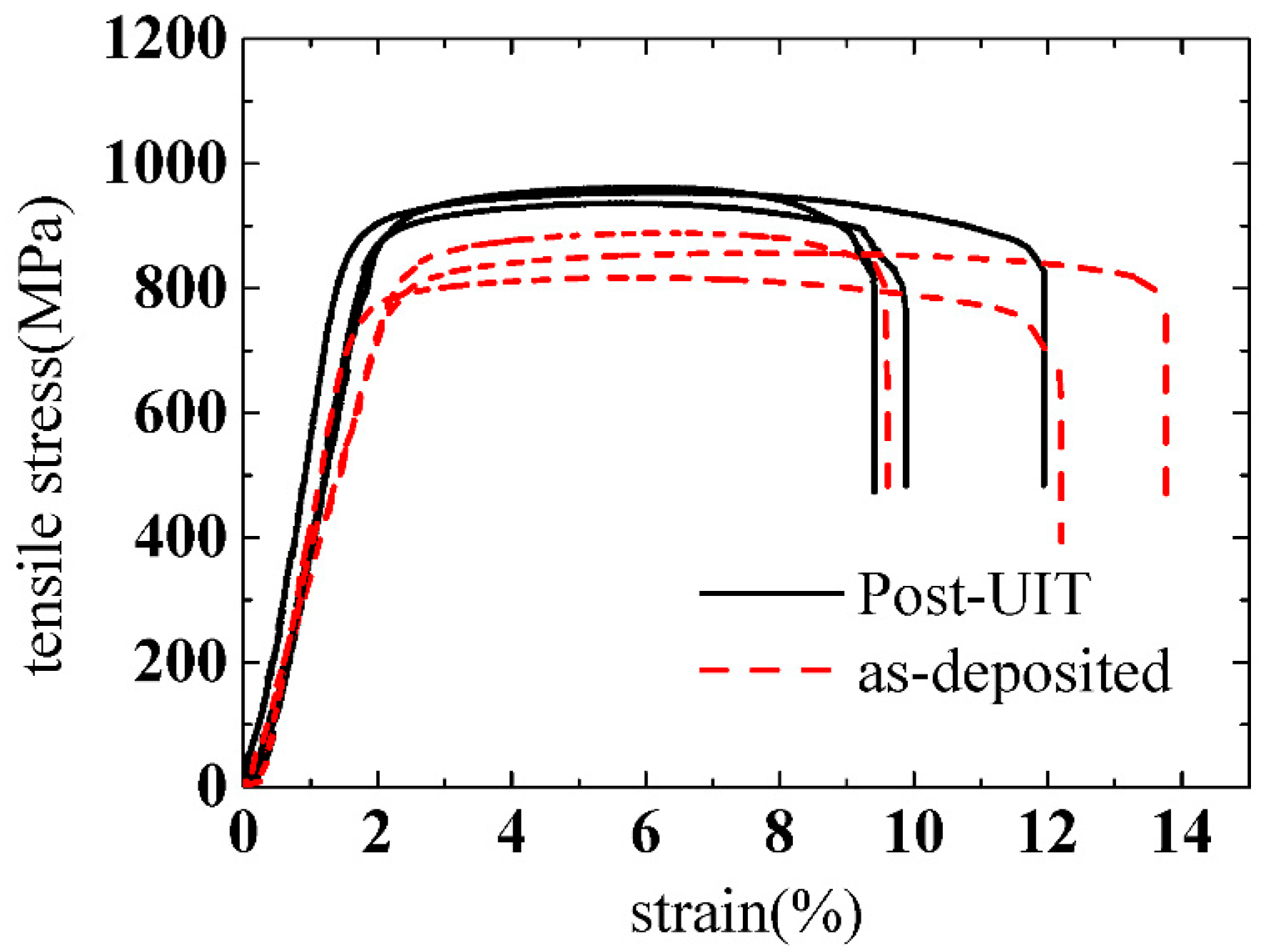
(3)
UIT improved the mechanical properties of the samples fabricated by WAAM. The tensile strength of the post-UIT samples (934 MPa) was higher than that of the as-deposited samples (870 MPa). However, the ductility of the post-UIT samples (10.29%) was not as high as the as-deposited samples (11.95%).
In this study, a UIT-assisted WAAM process is proposed to obtain samples with better performance in regard to residual stress, microstructure, and mechanical strength. The findings may be helpful in the manufacturing of low-cost, high wear-resisting titanium alloys.

Author Contributions

methodology, C.L.; formal analysis, X.J.; data curation, Y.Y.; writing—original draft preparation, Y.Y.; writing—review and editing, M.X. and H.F.; funding acquisition, J.L. and S.M.

Funding

This work was financially supported by the National Natural Science Foundation of China (No. 51875041, 51875042).

Conflicts of Interest

The authors declare no conflict of interest. The funders had no role in the design of the study; in the collection, analyses, or interpretation of data; in the writing of the manuscript, or in the decision to publish the results.

References

  1. Ding, J.; Colegrove, P.; Mehnen, J.; Ganguly, S.; Sequeira Almeida, P.M.; Wang, F.; Williams, S. Thermo-mechanical analysis of Wire and Arc Additive Layer Manufacturing process on large multi-layer parts. Comput. Mater. Sci. 2011, 50, 3315–3322. [Google Scholar] [CrossRef] [Green Version]
  2. Mueller, D.H.; Mueller, H. Experiences using rapid prototyping techniques to manufacture sheet metal forming tools. In Proceedings of the ISATA Conference, Dublin, Ireland, 25–27 September 2000; Volume 9. [Google Scholar]
  3. Levy, G.N.; Schindel, R.; Kruth, J.P. Rapid manufacturing and rapid tooling with layer manufacturing (LM) technologies, state of the art and future perspectives. CIRP Ann. Manuf. Technol. 2003, 52, 589–609. [Google Scholar] [CrossRef]
  4. King, D.; Tansey, T. Rapid tooling: Selective laser sintering injection tooling. J. Mater. Process. Technol. 2003, 132, 42–48. [Google Scholar] [CrossRef]
  5. Ding, D.; Pan, Z.; Cuiuri, D.; Li, H. Wire-feed additive manufacturing of metal components: Technologies, developments and future interests. Int. J. Adv. Manuf. Technol. 2015, 81, 465–481. [Google Scholar] [CrossRef]
  6. Huang, C.; Zhang, Y.; Rui, V.; Shen, J. Dry sliding wear behavior of laser clad TiVCrAlSi high entropy alloy coatings on Ti–6Al–4V substrate. Mater. Des. 2012, 41, 338–343. [Google Scholar] [CrossRef]
  7. Zhen, L.I.; Tian, X.J.; Tang, H.B.; Wang, H.M. Low cycle fatigue behavior of laser melting deposited TC18 titanium alloy. Trans. Nonferr. Met. Soc. China 2013, 23, 2591–2597. [Google Scholar]
  8. Fessler, J.; Merz, R.; Nickel, A.; Prinz, F.B. Laser Deposition of Metals for Shape Deposition Manufacturing. In Proceedings of the Solid Freeform Fabrication Symposium, Austin, TX, USA, 12–14 August 1996; pp. 117–124. [Google Scholar]
  9. Ding, J.; Colegrove, P.; Mehnen, J.; Williams, S.; Wang, F.; Sequeira Almeida, P. A computationally efficient finite element model of wire and arc additive manufacture. Int. J. Adv. Manuf. Technol. 2014, 70, 227–236. [Google Scholar] [CrossRef]
  10. Colegrove, P.A.; Coules, H.E.; Fairman, J.; Martina, F.; Kashoob, T.; Mamash, H.; Cozzolino, L.D. Microstructure and residual stress improvement in wire and arc additively manufactured parts through high-pressure rolling. J. Mater. Process. Technol. 2013, 213, 1782–1791. [Google Scholar] [CrossRef]
  11. Gao, H.; Dutta, R.K.; Huizenga, R.M.; Amirthalingam, M.; Hermans, M.J.M.; Buslaps, T.; Richardson, I.M. Stress relaxation due to ultrasonic impact treatment on multi-pass welds. Sci. Technol. Weld. Join. 2014, 19, 505–513. [Google Scholar] [CrossRef]
  12. Mordyuk, B.N.; Prokopenko, G.I.; Milman, Y.V.; Iefimov, M.O.; Sameljuk, A.V. Enhanced fatigue durability of Al–6Mg alloy by applying ultrasonic impact peening: Effects of surface hardening and reinforcement with AlCuFe quasicrystalline particles. Mater. Sci. Eng. A 2013, 563, 138–146. [Google Scholar] [CrossRef]
  13. Roy, S.; Fisher, J.W.; Yen, B.T. Fatigue resistance of welded details enhanced by ultrasonic impact treatment (UIT). Int. J. Fatigue 2003, 25, 1239–1247. [Google Scholar] [CrossRef]
  14. Kudryavtsev, Y.; Kleiman, J. Fatigue Life Improvement of Welded Elements by Ultrasonic Peening. Weld. Technol. 2014, 58, 47–53. [Google Scholar]
  15. Mordyuk, B.N.; Prokopenko, G.I. Fatigue life improvement of α-titanium by novel ultrasonically assisted technique. Mater. Sci. Eng. A 2006, 437, 396–405. [Google Scholar] [CrossRef]
  16. Mordyuk, B.N.; Prokopenko, G.I. Ultrasonic impact peening for the surface properties’ management. J. Sound Vib. 2007, 308, 855–866. [Google Scholar] [CrossRef]
  17. Zhang, M.; Liu, C.; Shi, X.; Chen, X.; Chen, C.; Zuo, J.; Lu, J.; Ma, S. Residual Stress, Defects and Grain Morphology of Ti-6Al-4V Alloy Produced by Ultrasonic Impact Treatment Assisted Selective Laser Melting. Appl. Sci. 2016, 6, 304. [Google Scholar] [CrossRef]
  18. Bezençon, C.; Schnell, A.; Kurz, W. Epitaxial deposition of MCrAlY coatings on a Ni-base superalloy by laser cladding. Scr. Mater. 2003, 49, 705–709. [Google Scholar] [CrossRef]
  19. Kurz, W.; Bezençon, C.; Gäumann, M. Columnar to equiaxed transition in solidification processing. Sci. Technol. Adv. Mater. 2008, 2, 185–191. [Google Scholar] [CrossRef]
  20. Gäumann, M.; Bezençon, C.; Canalis, P.; KURZ, W. Single-crystal laser deposition of superalloys: Processing–microstructure maps. Acta Mater. 2001, 49, 1051–1062. [Google Scholar] [CrossRef]
  21. Wang, F.; Williams, S.; Colegrove, P.; Antonysamy, A.A. Microstructure and Mechanical Properties of Wire and Arc Additive Manufactured Ti-6Al-4V. Metall. Mater. Trans. A Phys. Met. Mater. Sci. 2013, 44, 968–977. [Google Scholar] [CrossRef]
  22. Babu, N.K.; Raman, S.G.S.; Mythili, R.; Saroja, S. Correlation of microstructure with mechanical properties of TIG weldments of Ti–6Al–4V made with and without current pulsing. Mater. Charact. 2007, 58, 581–587. [Google Scholar] [CrossRef]
  23. Sundaresan, S.; Ram, G.D.J. Use of magnetic arc oscillation for grain refinement of gas tungsten arc welds in α-β titanium alloys. Sci. Technol. Weld. Join. 2013, 4, 151–160. [Google Scholar] [CrossRef]
  24. Lathabai, S.; Jarvis, B.L.; Barton, K.J. Comparison of keyhole and conventional gas tungsten arc welds in commercially pure titanium. Mater. Sci. Eng. A 2001, 299, 81–93. [Google Scholar] [CrossRef]
  25. Sundaresan, S.; Ram, G.D.J.; Reddy, G.M. Microstructural refinement of weld fusion zones in α-β, titanium alloys using pulsed current welding. Mater. Sci. Eng. A 1999, 262, 88–100. [Google Scholar] [CrossRef]
Figure 1. Schematic representation of the theory of ultrasonic impact treatment: (a) the impact head of the ultrasonic impact treatment (UIT) system, (b) the UIT influence area along the deposition direction [14].
Metals 08 00934 g001
Figure 2. The wire and arc additive manufacturing (WAAM) equipment: (a) schematic view of the UIT assisted TIG (Tungsten Inert Gas Welding) deposition system, (b) image of the inert atmosphere chamber.
Metals 08 00934 g002
Figure 3. Schematic view of the hybrid manufacturing process of one layer. (a) the first step: Additive manufacturing process; (b) the second step: Ultrasonic impact treatment.
Metals 08 00934 g003
Figure 4. Optical image of the surface of (a) as-deposited and (b) post-UIT sample. (c) the dimensions of a typical tensile sample, (d) the sample after tensile test.
Metals 08 00934 g004
Figure 5. The macrostructure of the seven-layer sample from top layer to the interface of substrate which is perpendicular to the scanning direction: (a) the optical microscopy images (b) the grain morphology drawn from the OM images.
Metals 08 00934 g005
Figure 6. Schematic view of the grain growth of the UIT assisted WAAM process: (a) the deposition process for layer 1; (b) the UIT effect after deposition; (c) the remelting and recrystallization when the pulse arc is applied to layer 2.
Metals 08 00934 g006
Figure 7. The microstructure of the seven-layers samples: (a) the colonies of coarsen columnar grains of the as-deposited sample, (b) the colonies of short columnar grains of the post-UIT sample, (c) the colonies of equiaxed grains of post-UIT sample.
Metals 08 00934 g007
Figure 8. The tensile test result for both the post-UIT samples (black curves) and the as-deposited samples (red curves).
Metals 08 00934 g008
Table 1. The process parameters of deposition and ultrasonic impact treatment (UIT).
Process ParametersValues
Type of welding currentPulsed direct current (DC)
Peak time Current160 A
Pulse frequency1.6 Hz
Wire feed rate1 m/min
Scanning speed120 mm/min
Argon99.999% purity
Shield gas flow rate20 L/min
Arc length5.5 mm
Tungsten electrode diameter2.4 mm
UIT head scanning speed50 mm/min
UIT output frequency20 KHz
UIT output power0.8 kW
Table 2. The top region residual stress of both the single-layer and the seven-layer as-deposited and post-UIT samples.
SamplesVon Mises Residual Stress (MPa)
Seven layers without UIT250 ± 2.6
Seven layers with UIT56 ± 10.6
Single layer without UIT96 ± 17.6
Single layer with UIT54 ± 7.6

