Self-Lubricating PEO–PTFE Composite Coating on Titanium

1
Key Laboratory of Advanced Forging & Stamping Technology and Science (Yanshan University), Ministry of Education of China, Qinhuangdao 066004, China
2
School of Mechanical Engineering, Yanshan University, Qinhuangdao 066004, China
3
Aviation Key Laboratory of Science and Technology on Generic Technology of Self-lubricating Spherical Plain Bearing, Yanshan University, Qinhuangdao 066004, China
4
State Key Laboratory of Metastable Materials Science and Technology, Yanshan University, Qinhuangdao 066004, China
*
Author to whom correspondence should be addressed.
Metals 2019, 9(2), 170; https://doi.org/10.3390/met9020170
Submission received: 19 December 2018
/
Revised: 23 January 2019
/
Accepted: 30 January 2019
/
Published: 1 February 2019
(This article belongs to the Special Issue Plasmas Processes Applied on Metals and Alloys)
Abstract
:A self-lubricating plasma electrolytic oxidation–polytetrafluoroethylene (PEO–PTFE) composite coating was successfully fabricated on the surface of commercially pure titanium by a multiple-step method of plasma electrolytic oxidation, dipping and sintering treatment. The microstructure and tribological properties of the PEO–PTFE composite coating were investigated and compared with the PEO TiO2 coating and the PTFE coating on titanium. Results show that most of the micro-pores of the PEO TiO2 coating were filled by PTFE and the surface roughness of PEO–PTFE composite coating was lower than that of the PEO TiO2 coating. Furthermore, the PEO–PTFE composite coating shows excellent tribological properties with low friction coefficient and low wear rate. This study provides an insight for guiding the design of self-lubricating and wear-resistant PEO composite coatings.
1. Introduction
Titanium and its alloys are lightweight structural metals, exhibiting high strength-to-weight ratio and excellent corrosion resistance. Due to these advantages, they are widely used in many industries, especially the automotive, aerospace and shipping industries [1,2,3]. However, titanium alloys generally show low surface hardness and poor tribological properties, characterized by severe abrasive wear and adhesive wear, which seriously restricted their applications in field of machinery [4,5]. Thus, developing proper surface modification techniques to improve the tribological properties is a crucial step to expand the application scopes of titanium alloy. At present, the commonly used methods to enhance surface performance of titanium alloys mainly include physical vapor deposition [6], chemical vapor deposition [7], ion implantation [8], thermal spraying [9], plasma electrolytic deposition [10], plasma electrolytic oxidation (PEO) [11], etc. Among these techniques, PEO is a simple and environment-friendly process with rapid deposition of anodic oxide coating on the titanium surface. Moreover, PEO coatings show increased surface hardness and excellent wear resistance. In spite of these advantages, PEO coatings usually take on high surface roughness and porosity with high friction coefficient, which has limited the extensive industrial application of the PEO technique [12]. Therefore, improving the tribological properties of PEO coating, is the key to enlarge its application range. In the previous study, we have explored depositing diamond-like carbon (DLC) on the PEO coating by using the unbalanced magnetron sputtering technique. Although results show that the TiO2/DLC composite coating exhibits improved tribological properties with low friction coefficient and low wear rate, DLC coating deposition is an expensive and time-consuming process [13]. Furthermore, this technique is not favorable to producing coatings on complex-shaped specimens.
In general, using liquid lubricants can effectively reduce the friction coefficient of the PEO coatings and decrease the wear between the friction pairs. However, in some extreme conditions, such as high temperature and high vacuum, liquid lubricant would volatilize and cause lubrication failure. Solid lubricants commonly used in mechanical lubrication include graphite, hexagonal boron nitride (hBN), molybdenum disulfide (MoS2), polytetrafluoroethlene (PTFE), etc [4,11,14]. PTFE has good chemical stability and thermal stability, with excellent lubricating property in a relatively wide temperature range and almost all of the ambient atmosphere [15]. In recent years, some researchers have attempted to disperse PTFE particles into the electrolyte and directly incorporated these self-lubricating particles into the anodic coating during the PEO process, but the localized high temperature during the PEO process may cause the decomposition of PTFE. Consequently, it is difficult to control the content and distribution of PTFE in the composite coatings by this technique.
In this paper, with the aim of improving the tribological properties of the PEO coating, especially the lubricating property, the PEO coating was used as the substrate and then the solid lubricant PTFE was deposited directly on the surface of the PEO coating by dipping and sintering treatment to fabricate a PEO–PTFE composite coating. The surface of the PEO coating is characterized with lots of micro-pores and micro-cracks which ensured the probability to deposit the small sized solid lubricant into these micro-pores on the PEO coating. The microstructure and tribological properties of the PEO–PTFE composite coating were investigated using scanning electron microscopy (SEM), energy-dispersive X-ray spectroscopy (EDS), Raman, surface profiler and ball-on-plate tribometer test and then compared with the PEO TiO2 coating and the Ti-PTFE coating.
2. Materials and Methods
2.1. Preparation of Coatings
The commercially pure titanium was used as the substrate for preparing the PEO coating, and the titanium plate was cut into samples with a size of 25 × 70 × 2 mm. The chemical composition of the titanium substrate were Fe ≤ 0.30 %, Si ≤ 0.15 %, O ≤ 0.20 %, C ≤ 0.10 %, N ≤ 0.05 %, H ≤ 0.015 % and Ti balance. In preparation for PEO process, all samples were ground with SiC abrasive papers (from 150-grit to 1500-grit) and cleaned ultrasonically with 95% alcohol for 30 min. Then, all samples were cleaned with deionized water and air dried. A pulsed asymmetric bipolar AC power supply (MAO120HD-III, Xi’an University of Technology, China) was employed for the PEO process. The PEO of titanium was carried out under the mode of constant voltage and the parameters setting of PEO is listed in Table 1. The electrolyte used in the PEO process consisted of Na2SiO3 (15 g/L), Na3PO4 (10 g/L) and NaOH (1 g/L). During the PEO treatment, titanium samples and stainless steel plates were used as the anode and cathode, respectively. A circulating cooling system was used to keep the temperature of the electrolyte below 40 °C. After the PEO treatment, the coated samples were cleaned with deionized water and dried at ambient temperature.
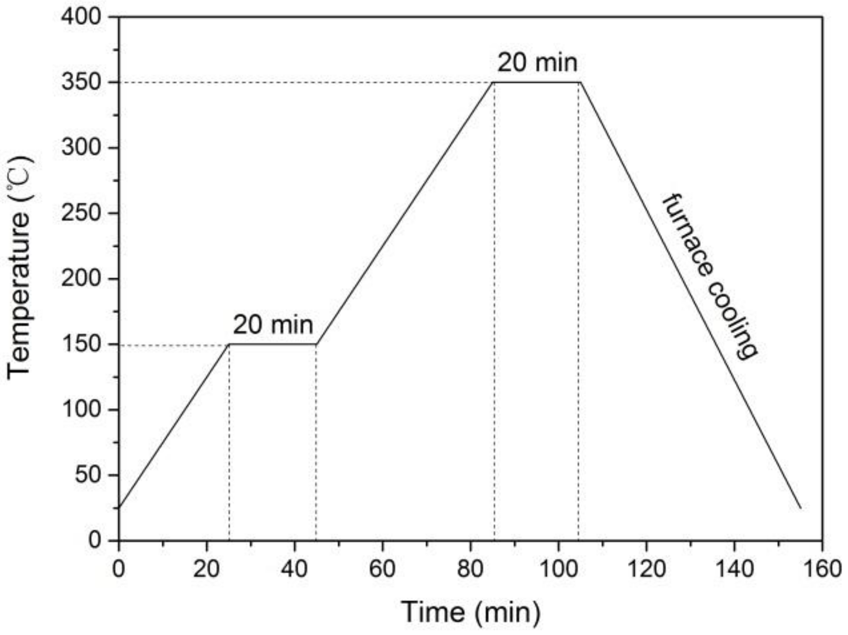
After the PEO treatment, the samples were subjected to dipping and sintering treatment to fabricate the PEO–PTFE composite coating. The PEO samples were immersed in PTFE dispersion (Shanghai Aladdin Bio-Chem Tech Co. LTD, Shanghai, China) heated to 50 °C and held for 20 min in a thermostat water bath, and then put into a muffle furnace (TESE, RXF1400-5-12, Shanghai, China). Figure 1 shows the process of sintering treatment for PEO–PTFE composite coating. Firstly, all coated samples placed in the muffle furnace were heated from room temperature to 150 °C with a heating rate of 5 °C/min, keeping the temperature at 150 °C for 20 min. After that, the temperature was increased to 350 °C with a heating rate of 5 °C/min, holding at the temperature of 350 °C for 20 min. Finally, all samples were cooled to room temperature inside the furnace. Following the same procedure as mentioned above, the PTFE coating directly deposited on the titanium was fabricated.
2.2. Characterization of Coatings
The surface morphologies of the coatings were studied by using scanning electron microscopy (SEM, SIGMA-500, ZEISS, Jena, Germany), equipped with EDS. The EDS was used to analyze the elementary composition of the PEO–PTFE composite coating. Raman spectra of the coatings were obtained with an Nd-YAG solid state laser (wavelength 532.0 nm) through the 50x objective lens of a Raman microspectrometer (Horiba, Kyoto, Japan). The surface roughness of the coatings was examined by a confocal microscope (Conscan Profilometer, Anton Paar Tritec SA, Peseux, Switzerland). The tribological properties of coatings were measured at room temperature under dry sliding condition by using a ball-on-plate reciprocating tribometer (Tribometer, Anton-Paar Tritec SA, Peseux, Switzerland). And the GCr15 stainless steel ball, with a diameter of 3 mm, was used as grinding material in the test. The friction coefficient and wear rate of the coatings was measured at different loads (2~8 N) with a sliding distance of 100 m. After the friction and wear tests, the wear tracks were measured by a surface profiler (MarSurf, Mahr, Göttingen, Germany). The wear rate of samples was calculated according to the formula: K = (S· l)/(F· L) [16], where S is the cross-sectional area of wear track (mm2), l is the length of wear track (mm), F is the applied load (N), L is the sliding distance (m).
3. Results and Discussion
3.1. Surface Morphology and Compositions
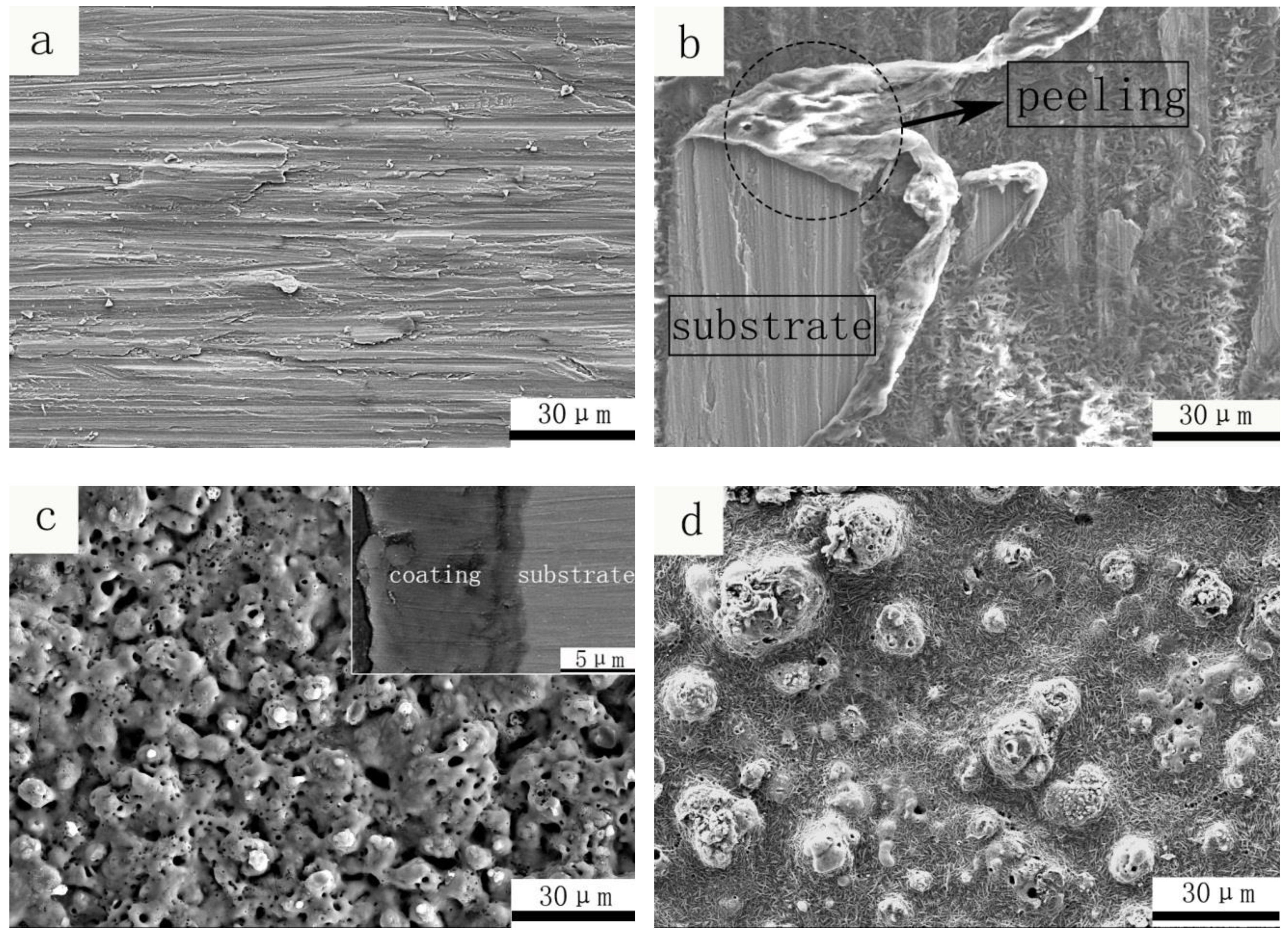
Figure 2a–d illustrates the morphologies of titanium substrate, Ti-PTFE coating, PEO TiO2 coating and PEO–PTFE composite coating. The SEM image of titanium substrate ground by sandpapers is shown in Figure 2a, from which lots of plough marks can be observed. This phenomenon reflects poor wear resistance of the commercially pure titanium. Figure 2b displays the morphology of the PTFE coating deposited directly on the surface of titanium substrate. It can be seen that the PTFE coating did not cover the substrate very well and peeled off at some areas, indicating the poor bonding between the PTFE coating and the relatively smooth titanium substrate. The typical surface morphology of PEO TiO2 coating fabricated in the silicate-phosphate electrolytic solution is presented in Figure 2c. It can be seen that the PEO TiO2 coating has a porous and rough surface structure, characterized with a large number of crater-like micro-pores and micro-protrusions. These micro-pores were formed by the plasma micro-arc discharges, which resulted in local high temperature and high pressure, causing the molten materials to erupt from the micro-arc discharge channels. Then, the erupted molten oxides solidified and accumulated around the micro-pores, leading to the formation of micro-protrusions. Although these surface structures led to a high surface roughness, this provided the possibility of depositing small sized solid lubricant into micro-pores and around micro-protrusions. In addition, the cross-sectional morphology of PEO TiO2 coating is also shown in Figure 2c. It can be seen that the oxide coating adhered tightly to the substrate and the average thickness of the oxide coating is around 10 μm.
Figure 2d shows the surface morphology of PEO–PTFE composite coating. Compared with Figure 2c, it can be observed that a great deal of micro-pores on the PEO TiO2 coating had been filled with PTFE and the porosity of the PEO TiO2 coating decreased significantly. During the process of sintering treatment, the sample was heated to 350 °C, which exceeded the melting point of PTFE materials [17]. As the PTFE has a dynamic viscosity in the melting state, the melted PTFE filled the pores of PEO and formed a continuous composite PEO–PTFE coating [18,19,20]. Obviously, the rough and porous PEO surface enhanced the crosslinking and bonding performance of PTFE materials to the bottom of the TiO2 coating.
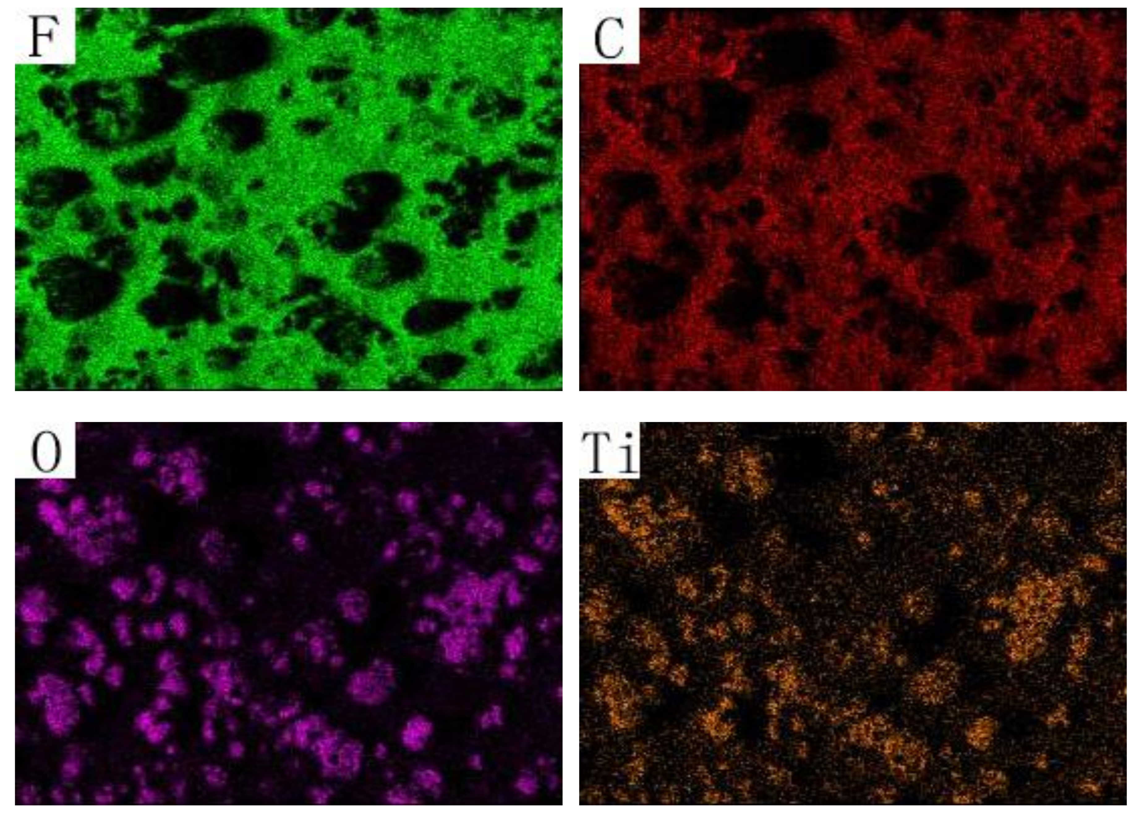
The EDS elemental maps of the PEO–PTFE composite coating is shown in Figure 3, which are obtained from the EDS scanning of Figure 2d. F and C elements were detected in the PEO–PTFE composite coating, indicating that PTFE materials deposited successfully on the PEO coating. From the distribution of F and C elements, it can be found that the most area of the PEO coating was covered by PTFE materials, except for the locations where the PEO oxides highly accumulated. This phenomenon is because of the fluidity of PTFE materials during the dipping and sintering processing. The mechanical interlinking formed between the porous PEO coating and the continuous PTFE materials after the sintering treatment. Such mechanical interlinking ensured a good bonding performance of the PEO–PTFE composite coating. In contrast to the single PEO TiO2 coating, this PEO–PTFE composite coating maintained the good wear-resistance of the ceramic PEO component while its PTFE component played the role as the friction-reducing lubricant. As reported in a recent study, a self-lubricating PEO coating was fabricated on AZ91 magnesium alloy via the in-situ incorporation of PTFE particles [21]. Results showed that the in-situ PTFE incorporation into the growing PEO coating resulted in non-uniform PTFE distribution and some PTFE-enriched ridge-like protrusions were formed on the coating surface. When the incorporation time was sufficient, the PTFE-enriched protrusions formed can act as lubricant reservoirs, leading to a low and stable friction coefficient. The present PEO–PTFE composite coating aimed to achieve uniform PTFE distribution by using the dipping and sintering treatments, ensuring even and sufficient PTFE lubricant supply during the friction and wear test.
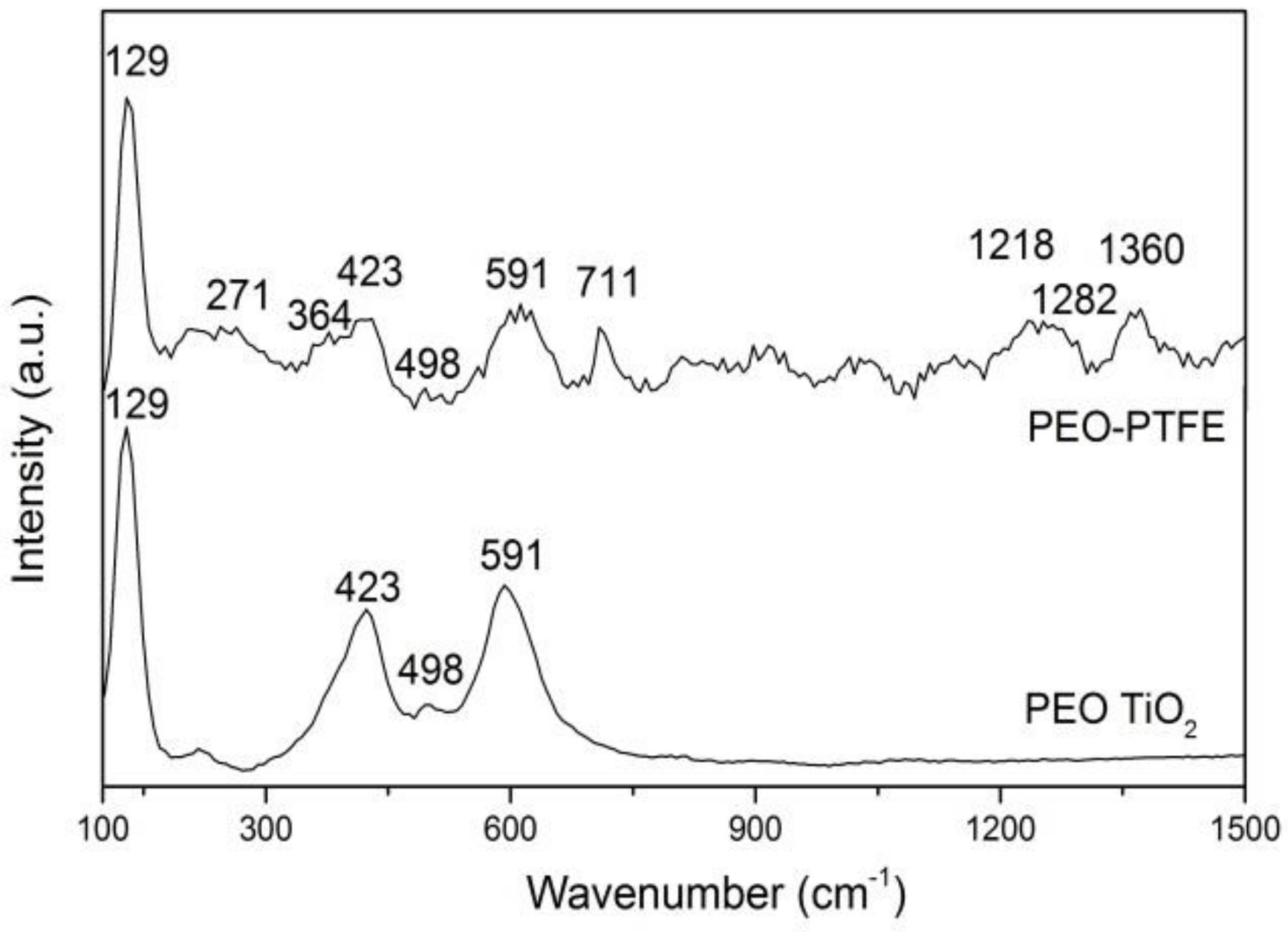
The Raman spectra of PEO TiO2 coating and PEO–PTFE composite coating are shown in Figure 4. Recorded Raman spectra were made in the frequency range from 100 to 1500 cm−1. It can be seen from the Raman spectrum of PEO TiO2 coating that bands shift located at 129 (Eg) and 498 (A1g) cm−1 positions originate from different modes of anatase TiO2 [22]. Bands shift located at 423 (Eg) and 591 (A1g) cm−1 positions originate from different modes of rutile TiO2. It can be inferred from Raman spectra of the PEO coating that there are two TiO2 crystal structures with anatase and rutile on the surface of the coating. According to the Raman spectrum of PEO–PTFE composite coating, one can see that some characteristic peaks of PTFE can be detected. The Raman peaks at 271, 364, 711 and 1360 cm−1 are related to the different vibrational modes of CF2 groups, whereas bands shift located at 1218 and 1282 cm−1 positions come from the bands C-C and CF, respectively [23]. The Raman result is consistent with the previous EDS analysis result, indicating the successful deposition of PTFE on the PEO coating.
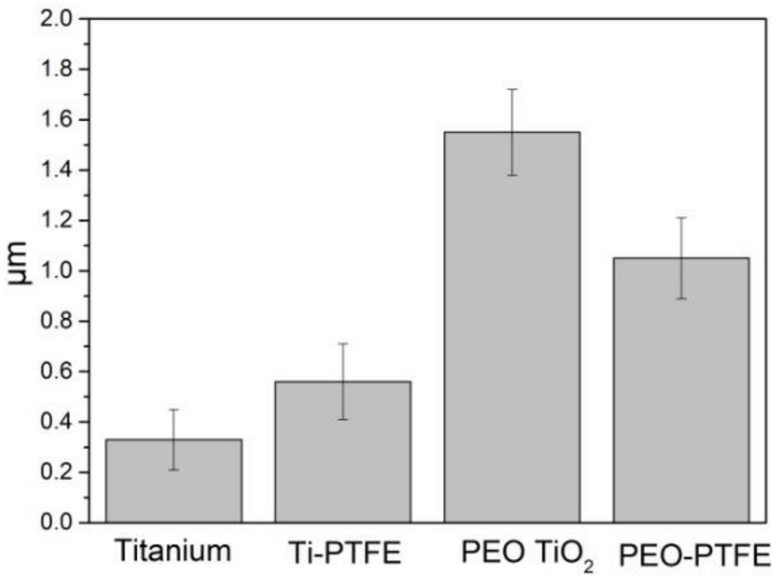
Figure 5 presents the surface roughness (Ra) of the titanium substrate, Ti-PTFE coating, PEO TiO2 coating, and PEO–PTFE composite coating. Compared with the titanium substrate, the roughness of Ti-PTFE coating slightly increased. This is because the Ti-PTFE coating deposited directly on the smooth titanium substrate was easy to peel off (see Figure 2b), causing a rougher surface than the titanium substrate. The roughness of the PEO TiO2 coating turned out to be the highest due to the existence of micro-pores and micro-protrusions on its surface (see Figure 2c). PTFE polymer materials deposited into the porous TiO2 coating (see Figure 2d) and formed the composite coating. Therefore, the roughness of the PEO–PTFE composite coating decreased significantly compared with the PEO TiO2 coating.
3.2. Tribological Behaviors
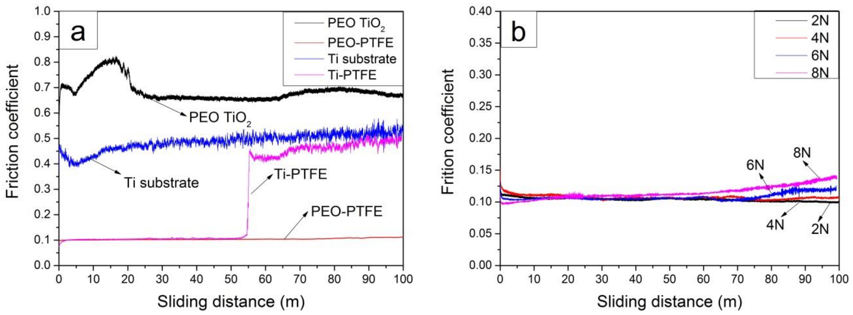
The tribological tests were performed at room temperature using a ball-on-plate reciprocating tribometer. Figure 6a shows the relationship between the friction coefficient and sliding distance of the titanium substrate, Ti-PTFE coating, PEO TiO2 coating and PEO–PTFE composite coating. From the friction coefficient curve of titanium substrate, it can be seen that the value remained about 0.5 after a slight fluctuation at the initial stage of the test. In the case of PEO TiO2 coating, this curve exhibited significant fluctuation before the sliding distance of about 20 m. After that, the friction coefficient gradually decreased to 0.65 and remained stable until the end of the test. This phenomenon was in connection with the unique structure of PEO TiO2 coating. The PEO coating typically has a rough and porous outer layer and a dense inner layer [13]. The porous outer layer featured with high surface roughness and varied internal microstructure, which contributed to the high and unstable friction coefficient at the initial stage of the test. With the gradual wearing-off of the porous outer layer, the GCr15 ball began to contact and slide against the dense inner layer of PEO TiO2 coating, resulting in the decreased and relatively stable friction coefficient.
Comparing the friction coefficient curves of the Ti-PTFE coating and the PEO–PTFE composite coating in Figure 6a, it can be seen that the friction coefficient of PEO–PTFE composite coating remained stable at 0.1 during the whole process of the test. For the Ti-PTFE coating, the friction coefficient was about 0.1 from the beginning until the sliding distance of 55 m and then increased sharply to about 0.4, which was close to the coefficient of titanium substrate. This result indicated that the Ti-PTFE coating had been worn off after a certain sliding distance. Afterwards, the friction behavior occurred between the grinding ball GCr15 and titanium substrate. As shown in Figure 2b, the PTFE coating exhibited poor adhesion to the titanium substrate. Therefore, it was easily damaged and peeled off in the process of reciprocating friction and wear. In the case of the PEO–PTFE composite coating, its long-term low friction coefficient proved that depositing of PTFE materials can effectively improve the friction property of PEO TiO2 coating. Also, it is demonstrated that the self-lubricating friction behavior occurred between the grinding pairs.
Figure 6b shows the relationship between the friction coefficient and sliding distance of the PEO–PTFE coating under different loads. It can be observed that when the load was 2 N and 4 N, the friction coefficient was stable at about 0.1. Under the higher load of 6 N and 8 N, the friction coefficient of the self-lubricating PEO–PTFE composite coating increased slightly with the increase of the sliding distance, but was still lower than 0.15. The friction coefficient curves of the self-lubricating PEO–PTFE composite coating under different loads consistently appeared to be low and stable, indicating that the self-lubricating PEO–PTFE composite coating has a good load-bearing capacity. Recently, Wang et al. constructed a lubricant composite coating on Ti6Al4V alloy using micro-arc oxidation and grafting hydrophilic polymer [24]. Results showed that the composite coating exhibited the low friction coefficient and favorable wear resistance in water under a low contact stress of 1.52 MPa. It was explained that the hydrophilic polymer formed a hydrated lubricating layer through the interaction with water and the TiO2 ceramic layer provided the resistance to wear.
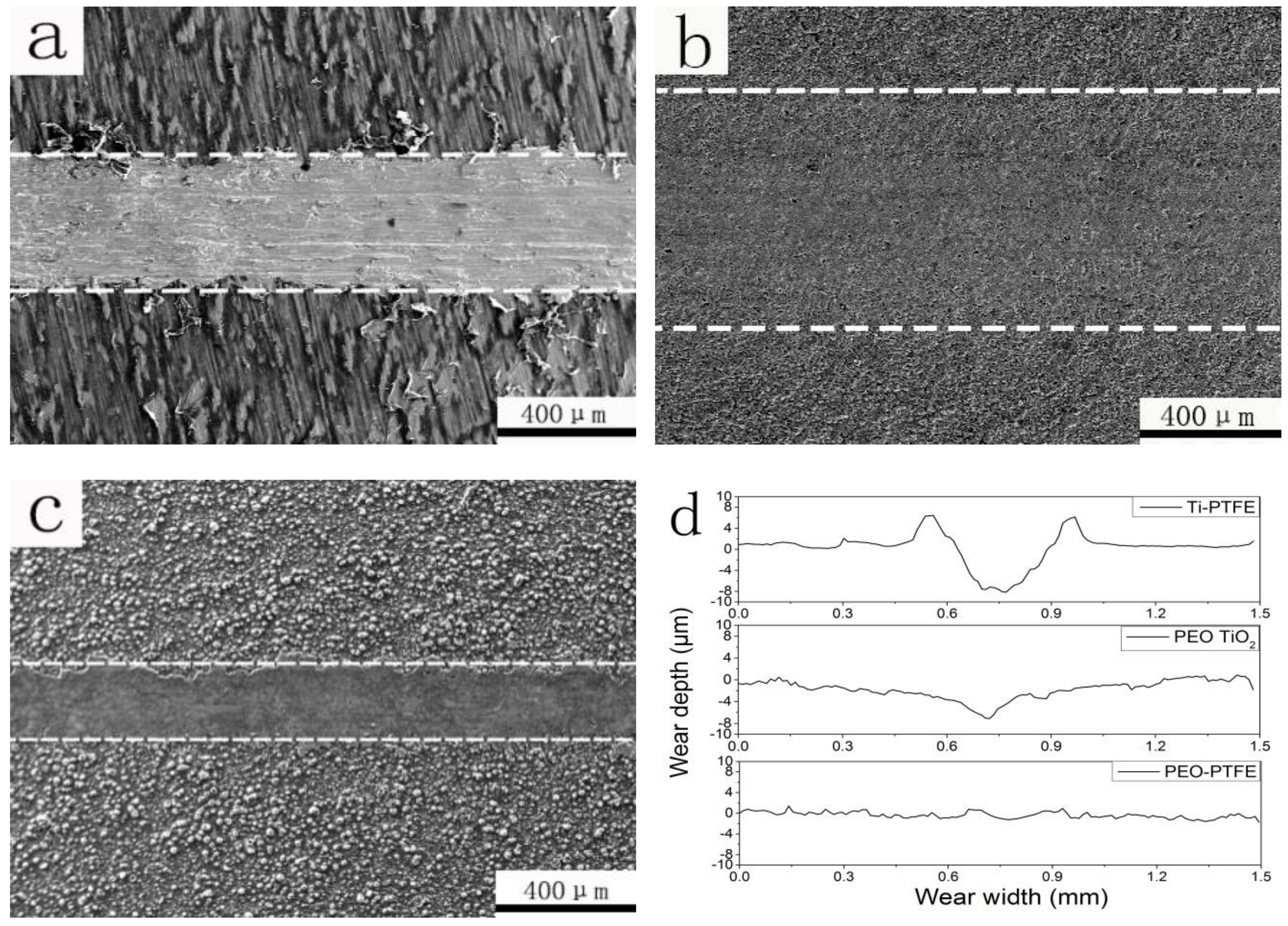
Figure 7a–c presents the SEM images of wear tracks of the Ti-PTFE coating, PEO TiO2 coating and the PEO–PTFE composite coating after a sliding distance of 100 m under the normal load of 4 N. The cross-sectional profiles of wear tracks are shown in Figure 7d. From the wear track profiles and worn morphologies of the coated samples, it can be noticed that the wear track of Ti-PTFE coating was narrower and deeper than the PEO TiO2 coating. Due to the loose adhesion of PTFE coating to titanium substrate, the PTFE coating was easily peeled off and damaged. After the PTFE coating was worn out, the titanium substrate was exposed to the grinding ball GCr15. Therefore, the poor wear resistance of titanium substrate resulted in a deeper wear track. For the PEO TiO2 coating, it can be seen that although the width of the wear track was large, the overall wear track was shallow. The ceramic PEO TiO2 coating has the advantage of high hardness and excellent wear resistance. Consequently, a lot of wear and tear of the GCr15 counterpart occurred with the proceeding wear test. Therefore, the contact areas between the grinding pairs increased, leading to the increase of the wear track width. For the PEO–PTFE composite coating, it can be seen from Figure 7c that the wear track was obviously shallower and narrower than both the Ti-PTFE coating and PEO TiO2 coating. This is because the deposition of PTFE polymer materials on the PEO TiO2 coating significantly improved the tribological properties of the PEO TiO2 coating. Firstly, the deposition PTFE materials in the PEO micro-pores or around the PEO micro-protrusions resulted in decreased the surface roughness and thus increased contact area and decreased contact stress between the friction pair, which avoided the rapid fracture and wearing-off of PEO outer layer to some extent. Secondly, the existence of self-lubricating PTFE component in the composite coating decreased the friction force and kept the GCr15 counterpart from severe wear.
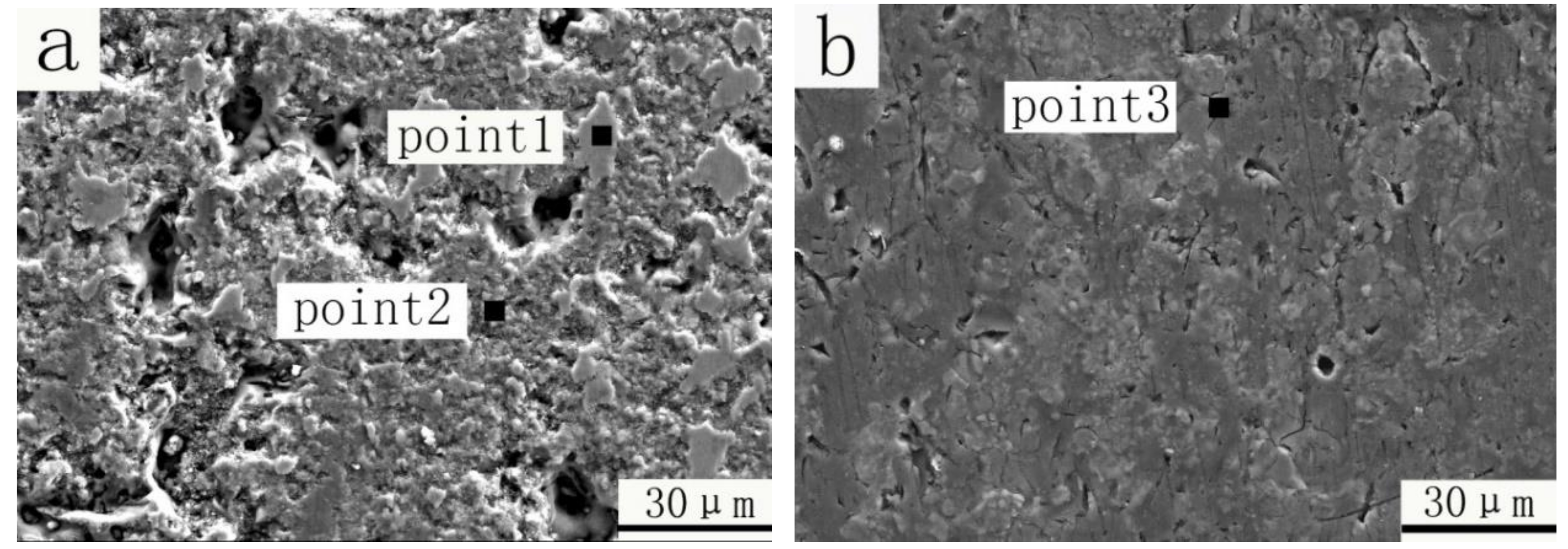
Figure 8 shows the micro worn morphologies of the PEO TiO2 coating and the self-lubricating PEO–PTFE composite coating after a sliding distance of 100 m under the 4 N loading. The element composition of wear tracks were examined by EDS and the results are listed in Table 2. For the worn track of PEO TiO2 coating (Figure 8a), it can be seen that there were still a great deal micro-pores after the tribo-test, indicating high porosity both in its surface and interior. The existence of micro-pores and debris greatly weakened the strength and toughness of the PEO TiO2 coating. It can be observed that there were two kinds of typical worn surface morphologies of the PEO TiO2 coating, as marked by point 1 and point 2 in Figure 8a. The first worn morphology (see point 1 in Figure 8a) was relatively smooth. A lot of Fe and O elements as well as a small quality of Cr element were detected (see Table 2), indicating that materials were transferred from the GCr15 ball to the PEO coating surface during the wear process. The second worn morphology (see point 2 in Figure 8a) was relatively rough. The brittle and porous surface layer of the PEO coating was crushed under the normal loading and formed lots of oxide debris at the initial stage of the tribo-test, which caused abrasive wear between the PEO coating and GCr15 ball during the subsequent tribo-test. Therefore, lots of O, Ti and Si elements and small amounts of Fe elements derived from GCr15 ball were detected (see Table 2).
As shown in Figure 8b, the worn surface morphology of the self-lubricating PEO–PTFE composite coating was obviously different from the PEO TiO2 coating. There were only a small number of micro-pores being observed on the worn surface, indicating a compact worn surface of the self-lubricating PEO–PTFE composite formed by repeated crushing of PTFE polymer materials and PEO TiO2 coating. In addition, a lot of F and C elements (see point 3 in Figure 8b and Table 2) were detected on the worn surface, demonstrating the formation of self-lubricating film. As PTFE polymer materials deposited into the PEO TiO2 coating, the porous surface was covered by the self-lubricating materials. The micro-pores were sealed by the solid lubricant. In the process of friction, a lubricating film would be formed on the friction contact surface. As a result, the sliding pairs in the contact surface were changed from the steel ball versus the composite coating to PTFE transfer film on the surface of the steel ball versus PTFE materials. Because of the poor adhesion between the PTFE transfer film and the steel ball, the transfer film usually fell off under the obstacle of the abrasive particle [25]. But the self-lubricating materials stored in the micro-pores provided continuous supply for the formation of the self-lubricating film. As the sliding distance increased, the PEO TiO2 component played a role as a wear-resistant reinforcing phase and supported the self-lubricating film.
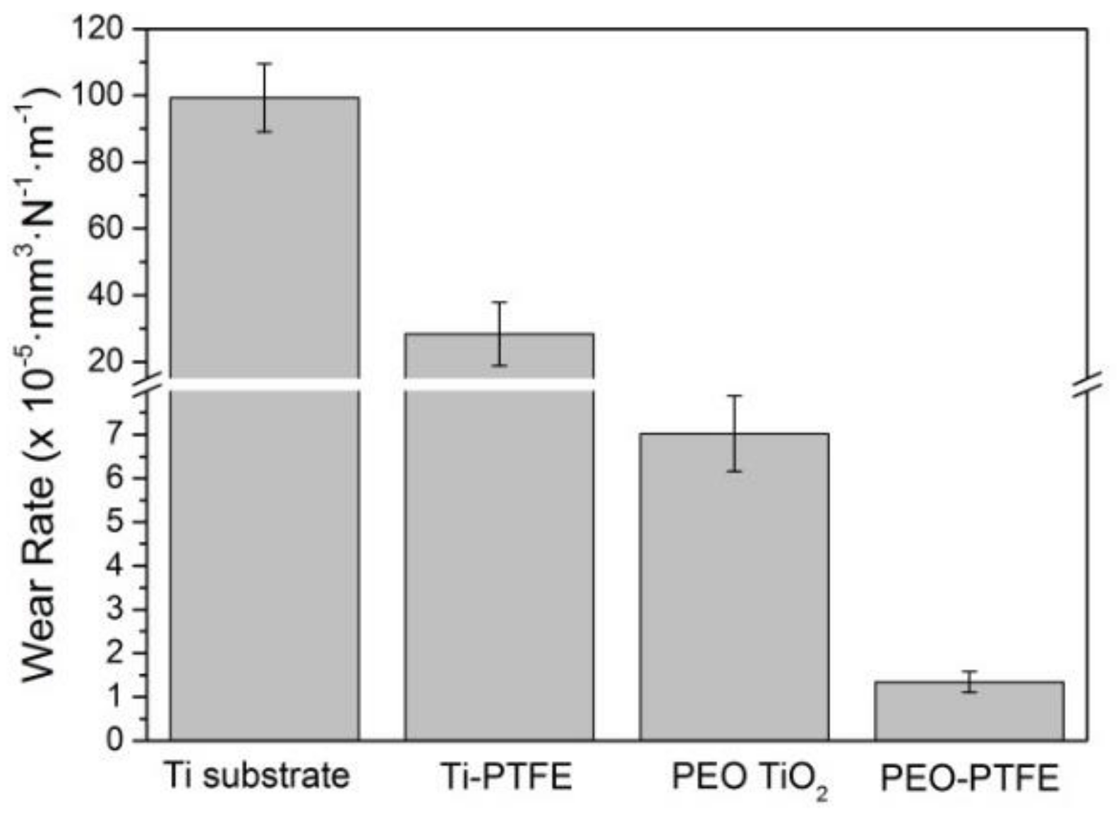
Figure 9 shows the wear rate of all samples against the counterpart GCr15 ball after the sliding test under the normal load of 4 N and a sliding distance of 100 m. During the process of sliding, the titanium substrate sample suffered from severe wear and tear, mainly due to its low hardness. Therefore, the wear rate value of the titanium substrate is large, which is 99.27 × 10⁻⁵ mm3·N−1·m−1. For the Ti-PTFE sample, the average wear rate was 28.39 × 10⁻⁵ mm3·N−1·m−1, smaller than that of the titanium substrate sample, because there was self-lubricating friction behavior at the beginning stage of the tribo-test (see Figure 6a). When the PTFE coating was worn off and the self-lubricating film failed, the bottom titanium substrate began to be subject to wear. From Figure 9, it can be seen that the wear rate of the PEO TiO2 coating (7.02 × 10⁻⁵ mm3·N−1·m−1) was smaller than that of both the titanium substrate and Ti-PTFE samples. The PEO TiO2 coating sample has higher hardness than Ti and Ti-PTFE samples, leading to the decrease of wear rate. The wear rate of the self-lubricating PEO–PTFE composite coating was 1.34 × 10⁻⁵ mm3·N−1·m−1, which is the smallest among all the samples. As the PTFE was integrating into the PEO coating and filling into the micro-pores, the high hardness of PEO coating and the good lubrication of PTFE combined to increase the wear resistance and decrease the friction coefficient.
4. Conclusions
The self-lubricating PEO–PTFE composite coating was successfully fabricated on the titanium surface by the combined methods of plasma electrolytic oxidation, dipping and sintering. Most micro-pores of the PEO TiO2 coating were effectively filled with PTFE and the surface roughness of the PEO TiO2 coating decreased significantly. The fabricated PEO–PTFE composite coating, integrating the advantages of wear resistance of the PEO TiO2 coating and the self-lubrication of PTFE polymer materials, exhibited a low friction coefficient and wear rate. The friction coefficient of the PEO–PTFE composite coating was much smaller than that of PEO TiO2 coating and remained stable (around 0.1) under different loads. The PEO–PTFE composite coating was more durable than the single PTFE coating and its wear rate was about 5 times lower than that of the PEO TiO2 coating.
Author Contributions
Z.C. and L.R. conceived and designed the experiments; T.W. and Y.L. performed the experiments; L.R. and T.W. analyzed the data and wrote the paper; Z.C. supervised the work; L.Q. contributed analysis tools.
Funding
This research was supported by Natural Science Foundation (E2016203270) and Returned Overseas Chinese Talents Foundation (CL201726) of Hebei Province, and the Fundamental Research Foundation (020000904) and Doctoral Foundation (B942) of Yanshan University.
Conflicts of Interest
The authors declare no conflict of interest.
References
- Diamanti, M.V.; Sebastiani, M.; Mangione, V.; Del Curto, B.; Pedeferri, M.P.; Bemporad, E.; Cigada, A.; Carassiti, F. Multi-step anodizing on Ti6Al4V components to improve tribomechanical performances. Surf. Coat. Technol. 2013, 227, 19–27. [Google Scholar] [CrossRef]
- Meng, F.; Li, Z.; Liu, X. Synthesis of tantalum thin films on titanium by plasma immersion ion implantation and deposition. Surf. Coat. Technol. 2013, 229, 205–209. [Google Scholar] [CrossRef]
- Yuan, X.; Tan, F.; Xu, H.; Zhang, S.; Qu, F.; Liu, J. Effects of different electrolytes for micro-arc oxidation on the bond strength between titanium and porcelain. J. Prosthodont. Res. 2017, 61, 297–304. [Google Scholar] [CrossRef] [PubMed]
- Ao, N.; Liu, D.; Wang, S.; Zhao, Q.; Zhang, X.; Zhang, M. Microstructure and tribological behavior of a TiO2/hBN composite ceramic coating formed via micro-arc oxidation of Ti–6Al–4V alloy. J. Mater. Sci. Technol. 2016, 32, 1071–1076. [Google Scholar] [CrossRef]
- Aliofkhazraei, M.; Sabour Rouhaghdam, A.; Shahrabi, T. Abrasive wear behaviour of Si3N4/TiO2 nanocomposite coatings fabricated by plasma electrolytic oxidation. Surf. Coat. Technol. 2010, 205, S41–S46. [Google Scholar] [CrossRef]
- Marin, E.; Offoiach, R.; Regis, M.; Fusi, S.; Lanzutti, A.; Fedrizzi, L. Diffusive thermal treatments combined with PVD coatings for tribological protection of titanium alloys. Mater. Des. 2016, 89, 314–322. [Google Scholar] [CrossRef]
- Zhu, Y.; Wang, W.; Jia, X.; Akasaka, T.; Liao, S.; Watari, F. Deposition of TiC film on titanium for abrasion resistant implant material by ion-enhanced triode plasma CVD. Appl. Surf. Sci. 2012, 262, 156–158. [Google Scholar] [CrossRef]
- Jin, G.; Cao, H.; Qiao, Y.; Meng, F.; Zhu, H.; Liu, X. Osteogenic activity and antibacterial effect of zinc ion implanted titanium. Colloids Surf. B Biointerfaces 2014, 117, 158–165. [Google Scholar] [CrossRef]
- Daram, P.; Banjongprasert, C.; Thongsuwan, W.; Jiansirisomboon, S. Microstructure and photocatalytic activities of thermal sprayed titanium dioxide/carbon nanotubes composite coatings. Surf. Coat. Technol. 2016, 306, 290–294. [Google Scholar] [CrossRef]
- Yang, X.; Jiang, Z.P.; Ding, X.F.; Hao, G.J.; Liang, Y.F.; Lin, J.P. Influence of solvent and electrical voltage on cathode plasma electrolytic deposition of Al2O3 antioxidation coatings on Ti-45Al-8.5Nb alloy. Metals 2018, 8, 308. [Google Scholar] [CrossRef]
- Lu, X.; Mohedano, M.; Blawert, C.; Matykina, E.; Arrabal, R.; Kainer, K.U.; Zheludkevich, M.L. Plasma electrolytic oxidation coatings with particle additions—A review. Surf. Coat. Technol. 2016, 307, 1165–1182. [Google Scholar] [CrossRef]
- Wang, S.; Zhao, Q.; Liu, D.; Du, N. Microstructure and elevated temperature tribological behavior of TiO2/Al2O3 composite ceramic coating formed by microarc oxidation of Ti6Al4V alloy. Surf. Coat. Technol. 2015, 272, 343–349. [Google Scholar] [CrossRef]
- Chen, Z.X.; Ren, X.P.; Ren, L.M.; Wang, T.C.; Qi, X.W.; Yang, Y.L. Improving the tribological properties of spark-anodized titanium by magnetron sputtered diamond-like carbon. Coatings 2018, 8, 83. [Google Scholar] [CrossRef]
- Zhang, Y.; Li, C.; Jia, D.; Zhang, D.; Zhang, X. Experimental evaluation of the lubrication performance of MoS2/CNT nanofluid for minimal quantity lubrication in Ni-based alloy grinding. Int. J. Mach. Tools Manuf. 2015, 99, 19–33. [Google Scholar] [CrossRef]
- Zhang, R.; Zhao, J.; Liang, J. A novel multifunctional PTFE/PEO composite coating prepared by one-step method. Surf. Coat. Technol. 2016, 299, 90–95. [Google Scholar] [CrossRef]
- Kavimani, V.; Soorya Prakash, K.; Thankachan, T. Surface characterization and specific wear rate prediction of r-GO/AZ31 composite under dry sliding wear condition. Surf. Interfaces 2017, 6, 143–153. [Google Scholar] [CrossRef]
- Khatipov, S.A.; Kabanov, S.P.; Konova, E.M.; Ivanov, S.A.; Serov, S.A. Effect of PTFE irradiation above the melting point on ITS porosity. Radiat. Phys. Chem. 2012, 81, 273–277. [Google Scholar] [CrossRef]
- Gamboni, O.C.; Riul, C.; Billardon, R.; Bose Filho, W.W.; Schmitt, N.; Canto, R.B. On the formation of defects induced by air trapping during cold pressing of PTFE powder. Polymer 2016, 82, 75–86. [Google Scholar] [CrossRef]
- Bai, D.Y.; Bai, H.W.; Fu, Q. Recent progress on sintering molding of polymers. Polym. Bull. 2017, 10, 13–22. [Google Scholar] [CrossRef]
- Huang, Q.L.; Xiao, C.F.; Hu, X.Y.; Bian, L.N. Preparation and properties of poly (Tetrafluoroethylene) membrane. Polym. Mater. Sci. Eng. 2010, 26, 123–126. [Google Scholar] [CrossRef]
- Chen, Y.; Lu, X.; Blawert, C.; Zheludkevich, M.L.; Zhang, T.; Wang, F. Formation of self-lubricating PEO coating via in-situ incorporation of PTFE particles. Surf. Coat. Technol. 2018, 337, 379–388. [Google Scholar] [CrossRef]
- Chen, Z.X.; Zhou, K. Surface morphology, phase structure and property evolution of anodized titanium during water vapor exposure. Surf. Coat. Technol. 2015, 263, 61–65. [Google Scholar] [CrossRef]
- Wyszkowska, E.; Leśniak, M.; Kurpaska, L.; Prokopowicz, R.; Jozwik, I.; Sitarz, M.; Jagielski, J. Functional properties of poly(tetrafluoroethylene) (PTFE) gasket working in nuclear reactor conditions. J. Mol. Struct. 2018, 306–311. [Google Scholar] [CrossRef]
- Wang, K.; Xiong, D. Construction of lubricant composite coating on Ti6Al4V alloy using micro-arc oxidation and grafting hydrophilic polymer. Mater. Sci. Eng. C 2018, 90, 219–226. [Google Scholar] [CrossRef]
- Gong, D.L.; Xue, Q.J. Transfer and adhesive wear of polytetrafluroethylene and its composite materials. J. Solid Lubr. 1990, 10, 73–83. [Google Scholar] [CrossRef]
Figure 1.
Sintering treatment process.

Figure 2.
Morphologies of (a) titanium substrate; (b) Ti-polytetrafluoroethylene (PTFE) coating; (c) plasma electrolytic oxidation (PEO) TiO2 coating; (d) PEO–PTFE composite coating.
Figure 2.
Morphologies of (a) titanium substrate; (b) Ti-polytetrafluoroethylene (PTFE) coating; (c) plasma electrolytic oxidation (PEO) TiO2 coating; (d) PEO–PTFE composite coating.

Figure 3.
Energy-dispersive X-ray spectroscopy (EDS) elemental maps of PEO–PTFE composite coating.

Figure 4.
Raman spectra of the PEO TiO2 coating and PEO–PTFE composite coating.

Figure 5.
Surface roughness (Ra) of titanium substrate, Ti-PTFE coating, PEO TiO2 coating and PEO–PTFE composite coating.
Figure 5.
Surface roughness (Ra) of titanium substrate, Ti-PTFE coating, PEO TiO2 coating and PEO–PTFE composite coating.

Figure 6.
Friction coefficient of different samples against GCr15 after a sliding distance of 100 m (a) titanium substrate, Ti-PTFE coating, PEO TiO2 coating and PEO–PTFE composite coating under the load of 4 N; (b) PEO–PTFE composite coating under different loads.
Figure 6.
Friction coefficient of different samples against GCr15 after a sliding distance of 100 m (a) titanium substrate, Ti-PTFE coating, PEO TiO2 coating and PEO–PTFE composite coating under the load of 4 N; (b) PEO–PTFE composite coating under different loads.

Figure 7.
Scanning electron microscope (SEM) images and cross-sectional profiles of wear tracks after a sliding distance of 100 m under the 4 N load of the (a) Ti-PTFE coating; (b) PEO TiO2 coating; (c) PEO–PTFE composite coating; and (d) cross-sectional profiles of wear tracks.
Figure 7.
Scanning electron microscope (SEM) images and cross-sectional profiles of wear tracks after a sliding distance of 100 m under the 4 N load of the (a) Ti-PTFE coating; (b) PEO TiO2 coating; (c) PEO–PTFE composite coating; and (d) cross-sectional profiles of wear tracks.

Figure 8.
Micro worn morphologies after a sliding distance of 100 m under the load of 4 N: (a) PEO TiO2 coating; (b) the self-lubricating PEO–PTFE composite coating.
Figure 8.
Micro worn morphologies after a sliding distance of 100 m under the load of 4 N: (a) PEO TiO2 coating; (b) the self-lubricating PEO–PTFE composite coating.

Figure 9.
Wear rate of the titanium substrate, Ti-PTFE, PEO TiO2 coating and the self-lubricating PEO–PTFE composite coating under the load of 4 N and the sliding distance of 100 m.
Figure 9.
Wear rate of the titanium substrate, Ti-PTFE, PEO TiO2 coating and the self-lubricating PEO–PTFE composite coating under the load of 4 N and the sliding distance of 100 m.


Table 1.
The parameters setting of plasma electrolytic oxidation power supply.
| Parameter | Voltage (V) | Frequency (Hz) | Duty Ratio (%) | Processing Time (min) |
|---|---|---|---|---|
| Forward | 420 | 500 | 35 | 25 |
| Reverse | 50 | 500 | 15 |
Table 2.
Element composition of the PEO TiO2 coating and PEO–PTFE composite coating worn track after a sliding distance of 100 m under 4 N in Figure 8.
Table 2.
Element composition of the PEO TiO2 coating and PEO–PTFE composite coating worn track after a sliding distance of 100 m under 4 N in Figure 8.
| Element (wt %) | O | C | Fe | F | Si | Ti | Cr | P | Na |
|---|---|---|---|---|---|---|---|---|---|
| Point 1 | 33.3 | 5.7 | 55.8 | - | 1.2 | 3.3 | 0.7 | - | - |
| Point 2 | 47 | 7.7 | 10.1 | - | 17.6 | 16.2 | - | 1.4 | - |
| Point 3 | 34.2 | 20.5 | 0.3 | 20.2 | 20.1 | 1.9 | - | 1.6 | 1.2 |
© 2019 by the authors. Licensee MDPI, Basel, Switzerland. This article is an open access article distributed under the terms and conditions of the Creative Commons Attribution (CC BY) license (http://creativecommons.org/licenses/by/4.0/).
Share and Cite
MDPI and ACS Style
Ren, L.; Wang, T.; Chen, Z.; Li, Y.; Qian, L. Self-Lubricating PEO–PTFE Composite Coating on Titanium. Metals 2019, 9, 170. https://doi.org/10.3390/met9020170
AMA Style
Ren L, Wang T, Chen Z, Li Y, Qian L. Self-Lubricating PEO–PTFE Composite Coating on Titanium. Metals. 2019; 9(2):170. https://doi.org/10.3390/met9020170
Chicago/Turabian StyleRen, Limei, Tengchao Wang, Zhaoxiang Chen, Yunyu Li, and Lihe Qian. 2019. "Self-Lubricating PEO–PTFE Composite Coating on Titanium" Metals 9, no. 2: 170. https://doi.org/10.3390/met9020170
Note that from the first issue of 2016, this journal uses article numbers instead of page numbers. See further details here.