Article

GMAW Cold Wire Technology for Adjusting the Ferrite–Austenite Ratio of Wire and Arc Additive Manufactured Duplex Stainless Steel Components

Institute of Materials and Joining Technology, Otto von Guericke University Magdeburg, Universitaetsplatz 2, 39106 Magdeburg, Germany
*
Author to whom correspondence should be addressed.
Metals 2019, 9(5), 564; https://doi.org/10.3390/met9050564
Submission received: 27 March 2019 / Revised: 30 April 2019 / Accepted: 12 May 2019 / Published: 14 May 2019
(This article belongs to the Special Issue Arc-based Additive Manufacturing)

Abstract

:
The use of commercially available filler metals for wire and arc additive manufacturing (WAAM) of duplex stainless steel components results in a microstructure with a very low ferrite content. The ferrite–austenite ratio in the duplex stainless steel weld metal depends on both the cooling rate and particularly on the chemical composition. However, the research and testing of special filler metals for additive deposition welding using wire and arc processes is time-consuming and expensive. This paper describes a method that uses an additional cold wire feed in the gas metal arc welding (GMAW) process to selectively vary the alloy composition and thus the microstructure of duplex stainless steel weld metal. By mixing different filler metals, a reduction of the nickel equivalent and hence an increase in the ferrite content in additively manufactured duplex stainless steel specimens was achieved. The homogeneous mixing of electrode and cold wire was verified by energy dispersive spectroscopy (EDS). Furthermore, the addition of cold wire resulted in a significant increase in sample height while the sample width remained approximately the same.

1. Introduction

Duplex stainless steels (DSS) are steels with a dual-phase microstructure consisting of ferrite and austenite. Due to the high resistance to corrosive media (aqueous media containing H2S, chlorides and solutions with low pH values), the high resistance to pitting and stress corrosion cracking, as well as the high strength, DSS are particularly suitable for components at great sea depths and for applications in the chemical and food industries [1].
For successful welding of highly alloyed, corrosion-resistant DSS, several welding recommendations have been developed over the past decades that guarantee the required material-specific properties of the welds. These include, for example, the adherence to specific energy input per unit length and interpass temperatures, as well as the use of similar filler metals with an increased nickel content compared to the base metal. However, recent investigations show that the application of the welding recommendations results in a microstructure with disproportionately high austenite content in additive multilayer welds if these were produced with a cold metal transfer (CMT) process and one bead per layer [2,3,4,5]. The high austenite content, as well as the formation of secondary austenite, significantly reduces strength and corrosion resistance [3].
The modification of the alloying concept of the filler metals is an opportunity to reduce the austenite content in the weld metal. Since the production of many filler metals with modified alloy compositions is time-consuming and expensive, the chemical composition is to be adjusted by mixing commercially available wires via cold wire feed during gas metal arc welding (GMAW) with the CMT process. Therefore, the objective of these investigations was to qualify the GMAW–CMT cold wire technology as a method for the specific adaptation of the alloy composition of the weld metal.

2. Welding of Duplex Stainless Steels

2.1. Joint and Surface Welding

Current recommendations for the processing of DSS focus on the formation of a dual-phase microstructure consisting of ferrite and austenite. Furthermore, the goal is a microstructure without intermetallic phases and precipitations, which reduce the material properties such as strength, toughness and corrosion resistance. When welding 22%Cr DSS, the energy per unit length should be between 0.5–2.5 kJ/mm. The interpass temperature should not exceed 250 °C. Preheating and postheat treatment are not generally required [1,6].
When processing DSS, the cooling rate is of decisive importance for the ferrite–austenite ratio, since the austenite content of the weld metal significantly depends on the t12/8 cooling time [7]. Thus, similar filler metals with increased nickel content compared to the base metal are used for joint welding and cladding [8]. These filler metals ensure a sufficient proportion of austenite in the weld metal despite short cooling times. According to DIN EN ISO 17781, the final ferrite content of the as-welded weld metal has to be between 30–70% [9]. Welding without filler metal is not recommended unless postheat treatment is carried out [6].
Recommendations on shielding gases slightly diverge in literature. Multicomponent shielding gases with helium are particularly suggested in order to reduce the viscosity of the weld pool, to improve wetting, to cool more slowly and thus to form more austenite or, if necessary, to increase the welding speed. Nitrogen admixtures are also used to increase the proportion of austenite in the weld metal. To improve the penetration behaviour, CO2 additions of 2–3% maximum are recommended as well. [6,10,11,12,13].

2.2. Wire and Arc Additive Manufacturing

The layer-by-layer production of components by wire and arc welding offers numerous advantages. These include new design freedom, a high degree of material utilization, and the possibility of a more flexible, decentralized manufacturing [14,15,16].
Depending on the required wall thickness of the component, gas metal arc welding allows the selection of an appropriate process variant. For the production of thick-walled components, pulsed arc welding is conceivable, whereas the GMAW–CMT process is advisable for the production of thin-walled structures.
A challenge in wire and arc additive manufacturing (WAAM) is the very low cooling rate compared to joint welding. The low heat dissipation and the resulting low cooling rate can cause both high residual stresses and distortion as well as changes in the microstructure and cracking [17,18].
Preliminary investigations by Posch et al. [2] on the production of turbine blades by WAAM with the GMAW–CMT process and the standard filler metal G 22 9 3 N L show an excessively austenitic microstructure with a ferrite content of less than 30%. The microstructure of the welded turbine blade showed finely distributed secondary austenite in the ferrite grains. The surface roughness was comparable to that of sand castings. The tensile strength and toughness of the welded structure were within the specifications of the filler metal data sheet. However, the yield strength was approximately 10% below the specified value.
Stützer et al. [3] investigated the influence of different levels of energy per unit length on the component dimensions, as well as mechanical and corrosive properties in GMAW–CMT weld metals using the filler metal G 22 9 3. The structural welds were carried out with energies per unit length between 0.19–0.61 kJ/mm, achieving an average ferrite content of 30%. A slight increase in the ferrite content was recorded with decreasing energy per unit length. The top layer of the welded structures always showed the highest ferrite content. Austenite growth and secondary austenite formation were observed in the reheated layers below. This was attributed to the repeated heat input and to an increasing cooling time with increasing specimen height. Furthermore, it was determined that the strength transverse to the direction of the buildup is lower than in the direction of the buildup, and that the minimum requirements for the all-weld metal are only just fulfilled.
In the study by Höfer et al. [4], the suitability of the GMAW–CMT process for the production of a thin-walled component using the super duplex filler metal G 25 9 4 was examined. An outlet nozzle of a seawater desalination plant was used as a demonstration component. This component also had an average ferrite content of only about 30%. The analysis of the temperature cycle of a layer resulted in a dwell time of 228 s in the temperature range between 800–1200 °C.
Eriksson et al. [5] investigated the influence of different levels of energy per unit length in GMAW–CMT weld metals using the superduplex filler metal G 25 9 4. The energy per unit length was varied between 0.4–0.87 kJ/mm. The yield strength and tensile strength decreased with increasing energy per unit length. The achieved average ferrite contents were only around 20%, where the maximum ferrite content was detected in the top layer. Cr-nitrides in the ferrite grains of the HAZ as well as secondary austenite in reheated ferrite grains were detected in microscopic investigations.
Investigations on the effects of the thermal cycles in WAAM using the filler metal G 22 9 3 were recently carried out by Hosseini et al. [19]. Depending on the heat input and the reheating during welding of the subsequent layers, ferrite contents between 40–65% were detected. With higher energy per unit length and increasing number of layers, longer cooling times and increasing dwell times in the temperature range above 400 °C were observed. In contrast to the investigations described above, thick-walled structures with several beads per layer were produced using a conventional arc welding process in this study. The cooling conditions of these welds are therefore not directly comparable to those of the GMAW–CMT welding with only one bead per layer.
However, the focus of this study is the further development of filler metals for additive manufacturing of thin-walled structures using the CMT process. In this type of component production, the use of commercially available nickel-overalloyed wire electrodes leads to an excessive austenite content in the weld metal of both the standard duplex steel G 22 9 3 and the super duplex steel G 25 9 4. The reason for the excessive formation of austenite is the increasing cooling time with increasing specimen height as well as the repeated dwell time in the temperature range between 800–1200 °C during welding of the subsequent layers. As a result of the reduced heat dissipation during the manufacturing of thin walls, there are long cooling times, and the diffusion-controlled transformation of δ-ferrite into austenite is supported.

3. Methodical Approach

The process-related reduced cooling rate requires an adaptation of the filler metals to achieve a balanced microstructure with ferrite contents of 30–70% for wire and arc additive manufacturing of DSS components. One promising approach is to reduce the nickel content.
As there are no suitable, commercially available filler metals, the GMAW–CMT cold wire (CW) technology was tested as a method for producing specific alloy compositions. For this purpose, the maximum amount of cold wire feeding was initially determined. Then, the homogeneity of mixing of the electrode material and the cold wire was tested. A lean DSS alloy (0.31 wt.% Mo) was used as the cold wire, and a standard DSS alloy (3.09 wt.% Mo) was used as the wire electrode. The mixing ratio of electrode:cold wire was 3.3:1. The resulting molybdenum content was determined with at least ten measuring points per weld layer using the EDS line scan.
Hereafter, decreasing nickel contents in the standard DSS weld metal were generated by mixing two filler metals with different nickel contents. For this, a filler metal with about 9 wt.% Ni and a filler metal with about 5 wt.% Ni were used. By varying the cold wire percentage, the nickel content was precisely adjusted. The cold wire percentage was set by the cold wire feed speed. The layer structure and geometry of the specimens were evaluated by visual testing. The height and width of the specimens were determined in as-welded condition. On cross-sections of the specimens, the microstructure was evaluated using light microscopy, and the ferrite content was determined by magnetic induction using a Feritscope® MP3C by Helmut Fischer (Sindelfingen, Germany).

4. Materials and Methods

4.1. Filler Metals and Shielding Gas

A standard filler metal with a nickel content of 8.77 wt.% and a specially designed filler metal for 3D printing with a nickel content of 5.51 wt.% were used. In addition, a lean duplex filler metal was applied to examine the homogeneity of the mixing of the electrode and cold wire. Table 1 shows the chemical compositions of the used filler metals determined by optical emission spectroscopy and carrier gas melt extraction. The diameter of the filler metals was 1.2 mm each. All welds were produced with an inert shielding gas consisting of 70% argon and 30% helium.

4.2. Achieving Various Nickel Equivalents

Various nickel equivalents were adjusted by mixing the alloy types G 22 9 3 N L and GZ 22 5 3 L by cold wire feed during gas metal arc welding. The wire feed speed of the electrode was set at the welding power source and that of the cold wire at the separate cold wire feed unit. The wire feed rates were monitored by a wire feed sensor during the welding process.
Appropriate mixing ratios were previously computed based on the WRC-1992 diagram with the premise of increasing the ferrite content by decreasing the nickel content. The chromium and nickel equivalents were calculated using the chemical compositions in accordance with formulae (1) and (2):
CrEq = Cr + Mo + 0.7Nb,
NiEq = Ni + 35C + 20N + 0.25Cu,
The chemical symbols indicate the weight percentage of the element present. Table 2 shows the different mixing ratios with the calculated chromium and nickel equivalents, as well as the ferrite numbers (FN) determined using the WRC-1992 diagram.

4.3. Specimens and Process Parameters

The specimens were produced in the form of wall structures consisting of 20 layers with a length of 200 mm. The walls were welded layer-by-layer using the GMAW cold wire technology. To minimize the heat input as much as possible, the welds were carried out using the cold metal transfer (CMT) process. The deposition welds were performed with a neutral torch position, a contact tube distance of 12 mm, and a shielding gas flow rate of 18 l/min. The single layers were welded in PA (1G) position with alternating welding direction. Thus, it was welded alternately with a front-feeding and rear-feeding cold wire. The cold wire was fed at an angle of 35° in relation to the sheet plane and at a distance of 2 mm from the base of the electrode (see Figure 1).
The average energy per unit length was 0.44 kJ/mm. A maximum interpass temperature of 50 °C was always maintained. The interpass temperature was measured using a type K thermocouple. The welding parameters were kept constant over all layers. To ensure comparability between the specimens, all specimens were produced with the same parameter setting. The relevant parameters are listed in Table 3.

5. Results and Discussion

5.1. Process Stability and Application Limits

The melting of cold wire during gas metal arc welding is basically possible in combination with the energy reduced CMT process. However, the cold wire percentage that can be added is limited. The maximum possible wire feed speed ratio of the electrode to the cold wire is 3.3:1 for the applied parameter setting. With a further increase in the cold wire feed speed, the cold wire is melted incompletely, which causes process instabilities. More disadvantages of the cold wire technology exist for both a front-feeding and a rear-feeding cold wire (see Figure 2). A front-feeding cold wire results in a reduction of the height at the component edges. The cold wire is not melted at the beginning of the welding process because the arc only ignites when the electrode is in contact with the component. At this time, the cold wire is already positioned in front of the component. A rear-feeding cold wire causes sticking of the cold wire at the end of the component since the residual heat is insufficient for the complete melting of the cold wire after the arc has extinguished.

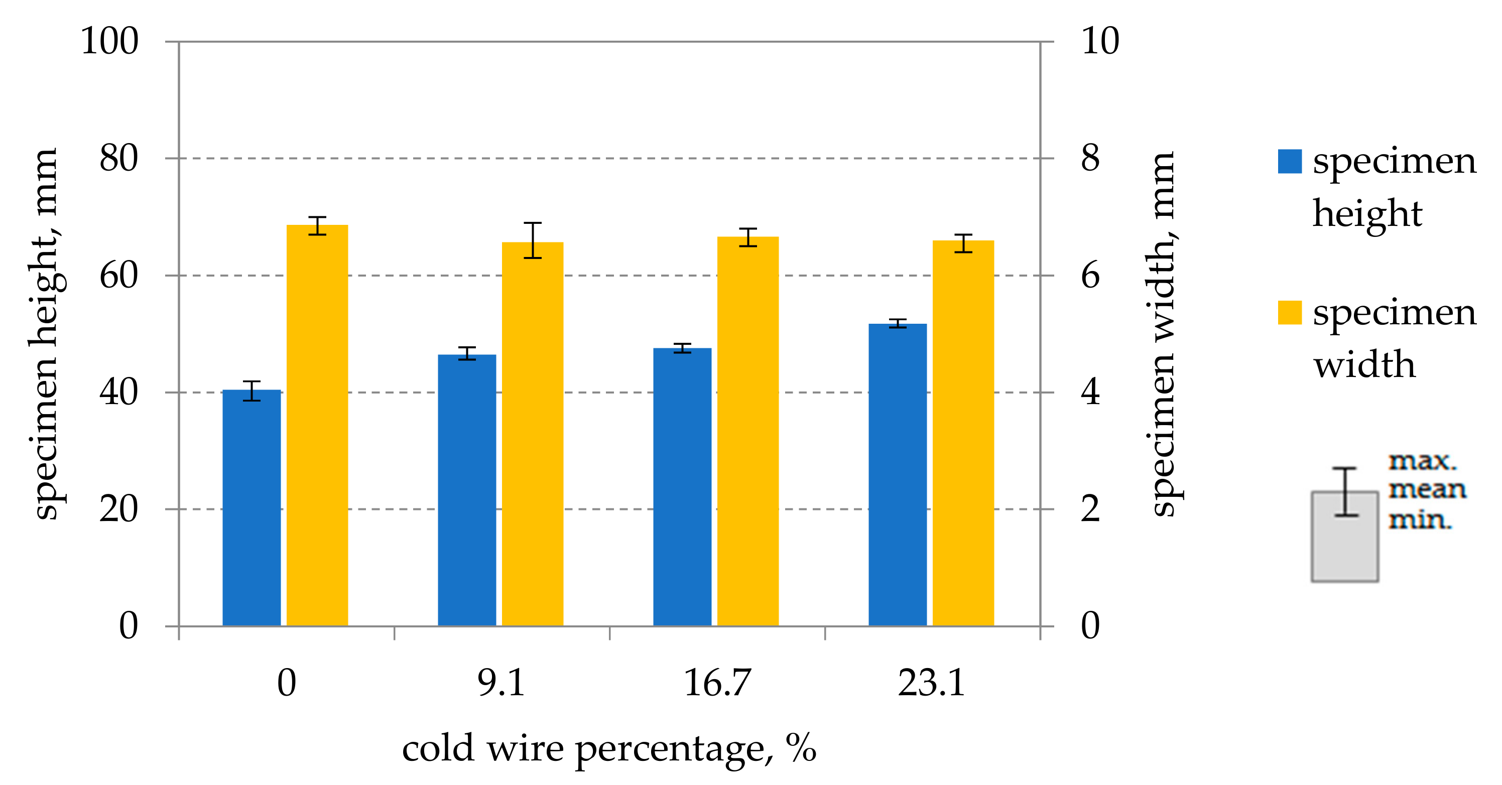
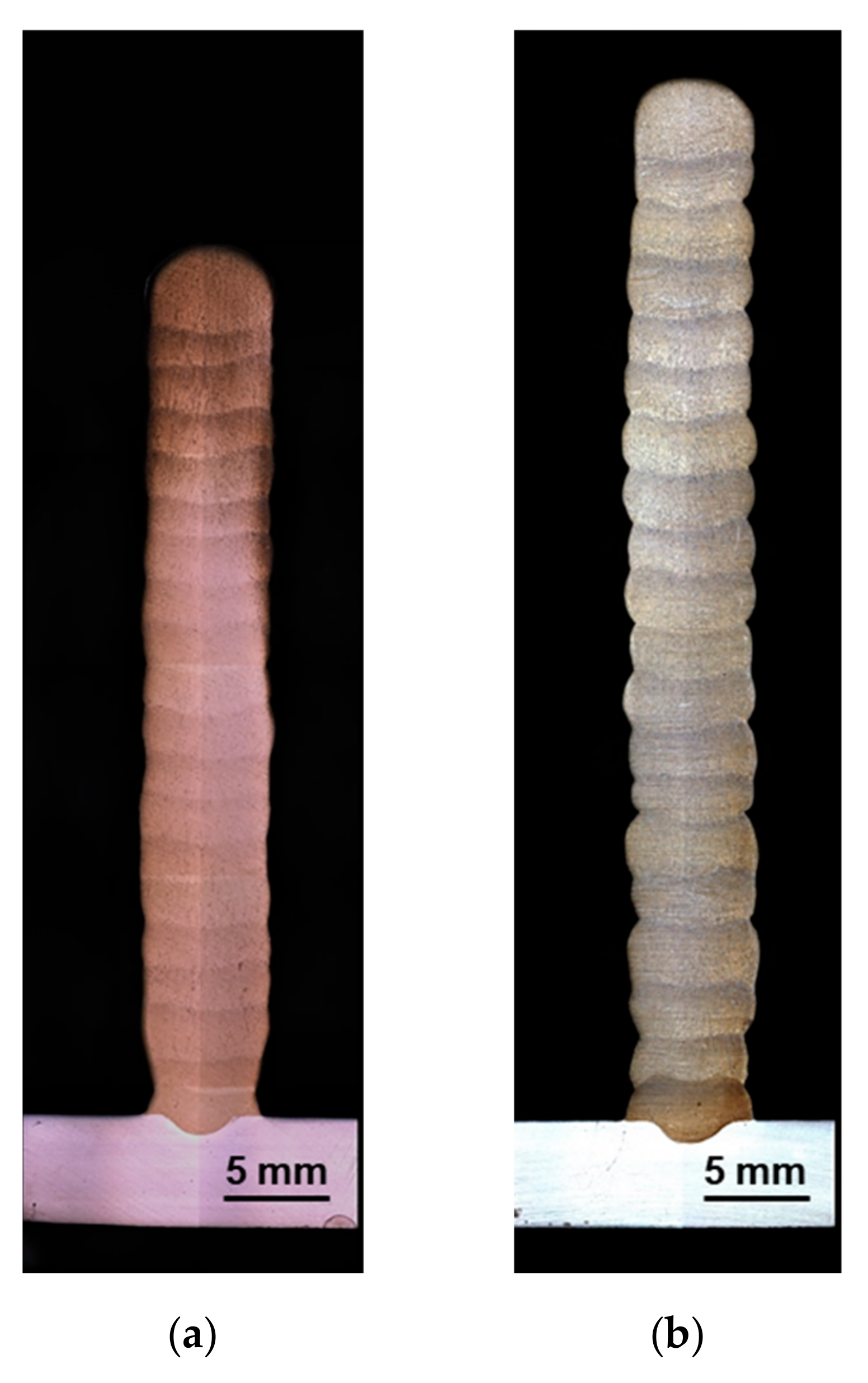
5.2. Layer Structure and Dimensions of the Specimen Geometries

The specimens, consisting of 20 layers, have a height of 40 mm and a width of 6.8 mm when welded without cold wire feed. The addition of a cold wire results in an increase in the specimen height, while the width remains approximately the same. The specimen height increases further with an increasing cold wire percentage (see Figure 3). The increase in specimen height is approximately 28% at a maximum cold wire percentage of 23.1%.
Figure 4 shows the layer structure of the specimens using macrosections. The cold wire feed does not only increase the height of the component but also the surface roughness. For components with functional surfaces, this means increased effort for the subsequent milling process, as well as lower component thicknesses in the final shape.

5.3. Mixing of Electrode and Cold Wire

The homogeneity of the mixing of wire electrode and cold wire was proven by EDS line scanning. For the analysis, the scanning electron microscope Scios DualBeam by FEI (Eindhoven Netherlands) with an SE detector was used. The operating voltage was 25 kV, and the working distance was 13.1 mm. Figure 5 shows the degree of mixing of the two filler metals with very different molybdenum contents (cf. Table 1). The molybdenum line scan was performed both in a layer with a front-feeding cold wire (layer 12) and with rear-feeding cold wire (layer 13). The molybdenum peak intensity was determined in the middle of the specimen with a distance of 100 μm between the individual measuring areas. The scan was carried out via area analysis covering an area of 19 × 14 μm2. The net intensity of the molybdenum peak varies over both layers by approximately 4 ± 2 area units (AU). The fluctuations occur evenly and periodically in both layers. However, these fluctuations are not the result of insufficient mixing. This is due to the distribution of ferrite and austenite in the analysed section of the specimen, as shown in Figure 6. In the case of unmixed zones where the cold wire predominates, the molybdenum peak intensity would be approximately zero. Since such areas cannot be identified, a homogeneous mixing of the filler metals can be assumed.
Electron microscopic examination of the analysed areas provides information on the scattering of the molybdenum peak intensities. The EDS spectra (Figure 6 right) show the distribution of elements of the total area in the SEM images (Figure 6 left). The molybdenum peak intensities are mainly dependent on the microstructure percentages in the measured area. A section with an even distribution of ferrite and austenite has an average net intensity of the MoL peak of 3.8 AU (see Figure 6a). If the analysed area predominantly contains ferrite, then IMoL, net = 6.7 AU (see Figure 6b). A predominantly austenitic analysis area results in a significantly lower peak intensity 2.4 AU (see Figure 6c).

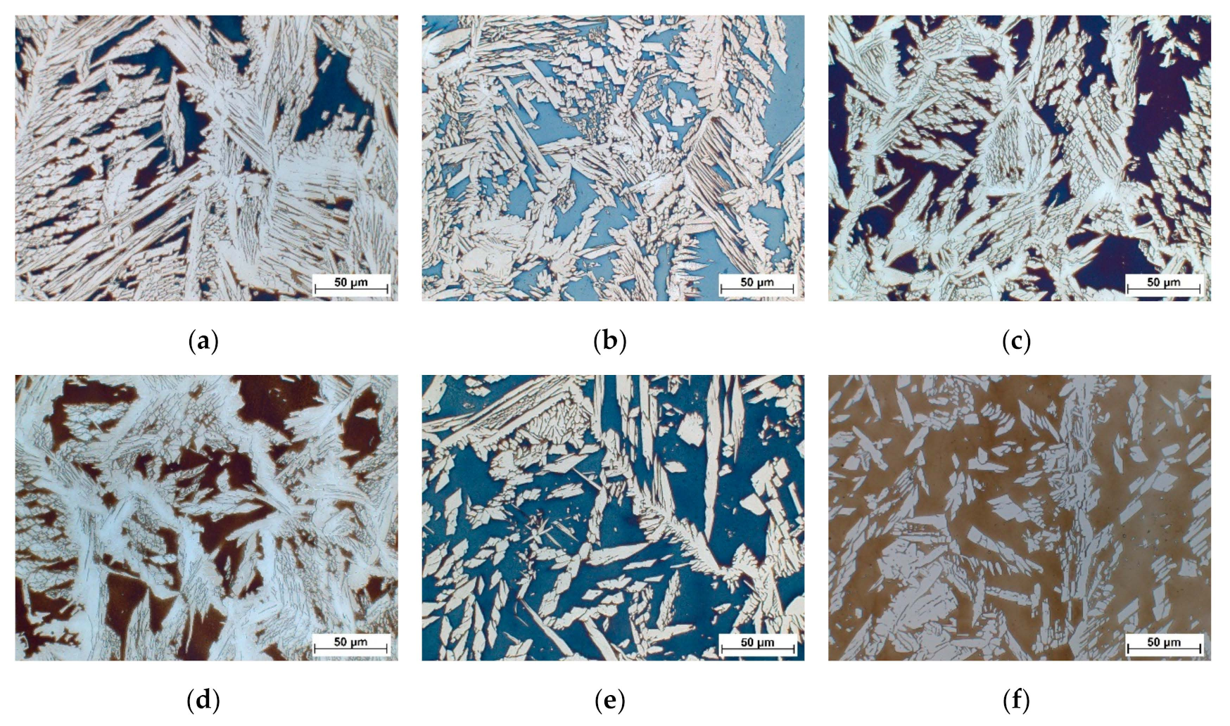
5.4. Achievable Ferrite-Austenite Ratios

Figure 7 shows the ferrite numbers of the specimens measured by magnetic induction using the Feritscope®. The use of the standard filler metal G 22 9 3 N L results in a value of 43 FN, which corresponds to a δ-ferrite content of 39% (FN = 1.1 x δ-ferrite [%] [20,21]). The ferrite content of the specimens increases as the percentage of filler metal GZ 22 5 3 L increases. The specimen, produced only with the filler metal GZ 22 5 3 L, reaches a ferrite content of 79 FN (approx. 72%).
The increase in the ferrite content is attributed to the decreasing nickel content. The tendencies of the measured and predicted ferrite numbers are basically the same. However, the ferrite numbers determined by WRC-1992 are always slightly higher than the measured values. The absolute deviation increases with increasing FN. A possible reason for the deviations between predicted ferrite numbers and ferrite numbers measured on the weld metal are burning loss and pickup of alloying elements during arc welding. The predicted ferrite numbers were calculated on the basis of the chemical composition of the filler metals. However, the actual chemical composition of the weld metal usually deviates from the predicted chemical composition due to burning loss and pickup. The cooling conditions also have a significant influence on the ferrite content and thus the FN. The cooling rates in WAAM processes do not correspond to the underlying cooling conditions of the WRC-1992 diagram, which may result in prediction inaccuracies.
The increase in the ferrite content determined with the Feritscope® can also be seen when looking at the micrographs in Figure 8. The micrographs were taken in the tenth layer of the welded wall structures. Due to etching with Beraha II, the ferritic matrix is brown or blue, and the austenite is white. However, in Figure 8a, only a very low ferrite content is present. This microstructural constituent continuously increases as the nickel content decreases (increase in the percentage of GZ 22 5 3 L from Figure 8a to Figure 8f). The highest ferrite content is found in the weld produced with 100% GZ 22 5 3 L (see Figure 8f).
All weld metals show a typical Widmanstätten microstructure. The austenite has grown mainly at the primary grain boundaries, but also partly as platelets within the ferrite grain.
The specimen produced with 100% of the filler metal G 22 9 3 (see Figure 8a) has very large austenitic side plates. The primary ferritic solidified weld metal is largely transformed to austenite. As already described, this can be explained on the one hand by a comparatively slow cooling rate due to the one-dimensional heat dissipation. On the other hand, further ferrite was transformed into austenite due to the reheating during welding of the subsequent layers. As the nickel content decreases (from Figure 8a to Figure 8f), the size of the austenite plates decreases. The specimen produced with 100% of the filler metal GZ 22 5 3 (see Figure 8f) has comparatively small austenite platelets. Only 35% of the primary ferritic solidified weld metal is transformed to austenite.
Micropores, non-metallic inclusions or intermetallic phases could not be observed in any microsection.
The investigations show that it is possible to influence the ferrite–austenite ratio by adjusting the nickel content of the filler metal. The optimum nickel content can be determined by mixing two different filler metals using cold wire technology. However, the mixing ratios are limited due to the maximum fusible cold wire. A higher percentage of filler wire could be achieved by using a hot wire instead of a cold wire. Thus, a wider range of adjustable mixing ratios would be possible.

6. Summary and Outlook

In this paper, the suitability of the GMAW cold wire technology as a method for adapting the alloying concept of filler metals for the additive welding of DSS components was examined. In addition to the wire electrode, approximately 23% cold wire could be melted in the welding experiments. The filler metals were homogeneously mixed. It was possible to achieve ferrite contents of 39–72% in the specimens by mixing two wires with different nickel contents.
The testing of mechanical weld metal properties such as toughness and strength, as well as tests for pitting corrosion resistance, will be part of future investigations. If the typical material characteristics cannot be achieved, it has to be examined if the performance can be improved by post heat treatment (solution annealing and quenching). Furthermore, the results may be used for the development of new alloy concepts.

Author Contributions

Conceptualization, J.S. and T.T.; Data curation, J.S. and T.T.; Funding acquisition, M.Z.; Investigation, J.S. and T.T.; Methodology, J.S. and T.T.; Project administration, M.Z.; Supervision, S.J.; Writing—original draft, J.S.; Writing—review & editing, B.W.

Funding

This research was funded by Arbeitsgemeinschaft industrieller Forschungsvereinigungen “Otto von Guericke” e.V. (AiF), grant number 20.361 B.

Acknowledgments

Excerpts of this work are part of an IGF research project. The IGF promotion plan (IGF-No. 20.361 B / DVS-No. 01.3060) of the Research Association on Welding and Allied Processes of the DVS, Aachener Straße 172, 40223 Düsseldorf has been funded by the AiF within the program for sponsorship by Industrial Joint Research (IGF) of the German Federal Ministry of Economic Affairs and Energy based on an enactment of the German Parliament. This support is gratefully appreciated.

Conflicts of Interest

The authors declare no conflict of interest.

References

  1. TMR Stainless. Practical Guidelines for the Fabrication of Duplex Stainless Steels, 3rd ed.; International Molybdenum Association (IMOA): London, UK, 2014. [Google Scholar]
  2. Posch, G.; Chladil, K.; Chladil, H. Material properties of CMT-metal additive manufactured duplex stainless steel blade-like geometries. Weld. World 2017, 61, 873–882. [Google Scholar] [CrossRef]
  3. Stützer, J.; Zinke, M.; Jüttner, S.; Findeklee, P. Additive Fertigung von Bauteilen aus Duplexstahl durch Schutzgasschweißen. In Proceedings of the Fachtagung Werkstoffe und Additive Fertigung, Potsdam, Germany, 22–26 April 2018; Deutsche Gesellschaft für Materialkunde e. V.: Berlin, Germany; pp. 103–108. [Google Scholar]
  4. Höfer, K.; Hälsig, A.; Mayr, P. Arc-based additive manufacturing of steel components—Comparison of wire- and powder-based variants. Weld. World 2018, 62, 243–247. [Google Scholar] [CrossRef]
  5. Eriksson, M.; Lervåg, M.; Sørensen, C.; Robertstad, A.; Brønstad, B.M.; Nyhus, B.; Aune, R.; Ren, X.; Akselsen, O.M. Additive manufacture of superduplex stainless steel using WAAM. MATEC Web Conf. 2018, 188. [Google Scholar] [CrossRef]
  6. Karlsson, L. Welding Duplex Stainless Steels—A Review of Current Recommendations. Weld. World 2012, 56, 65–76. [Google Scholar] [CrossRef]
  7. Lippold, J.C.; Kotecki, D.J. Welding Metallurgy and Weldability of Stainless Steels; John Wiley & Sons, Inc.: Hoboken, NJ, USA, 2005. [Google Scholar]
  8. Nassau, L.v.; Bekkers, K.; Hilkers, J.; Meelker, H. Das Schweißen der Superduplex-Stähle. Schweißen und Schneiden 1991, 136, 120–127. [Google Scholar]
  9. DIN EN ISO 17781:2017. Petroleum, Petrochemical and Natural Gas Industries—Test Methods for Quality Control of Microstructure of Ferritic/Austenitic (Duplex) Stainless Steels; Beuth: Berlin, Germany, 2017. [Google Scholar]
  10. Sathiya, P.; Aravindan, S.; Soundararajan, R.; Haq, A.N. Effect of shielding gases on mechanical and metallurgical properties of duplex stainless-steel welds. J. Mater. Sci. 2009, 44, 114–121. [Google Scholar] [CrossRef]
  11. Merkblatt DVS 0946. Empfehlungen zum Schweißen von Nicht Rostenden Austenitisch-Ferritischen Duplex- und Superduplexstählen; Deutscher Verband für Schweißen und verwandte Verfahren E.V.: Düsseldorf, Germany, 2004. [Google Scholar]
  12. Bhatt, R.B.; Kamat, S.H.; Ghosal, S.K.; De, P.K. Influence of nitrogen in the shielding gas on corrosion resistance of duplex stainless steel welds. J. Mater. Eng. Perform. 1999, 8, 591–597. [Google Scholar] [CrossRef]
  13. Pettersen, C.O.; Fager, S.A. Welding Practice for the Sandvik Duplex Stainless Steels SAF 2304, SAF 2205 and SAF 2507; AB Sandvik Steel: Sandviken, Sweden, 1995. [Google Scholar]
  14. Allen, J. An Investigation into the Comparative Costs of Additive Manufacture vs. Machine from Solid for Aero Engine Parts. In Proceedings of the Cost Effective Manufacture via Net-Shape Processing, Meeting Proceedings RTO-MP-AVT-139, Neuilly-sur-Seine, France, May 2006; Paper 17. pp. 17-1–17-10. [Google Scholar]
  15. Gebhardt, A. Generative Fertigungsverfahren. Additive Manufacturing und 3D Drucken für Prototyping—Tooling—Produktion, 4th ed.; Carl Hanser Verlag: München, Germany, 2013. [Google Scholar] [CrossRef]
  16. Lachmayer, R.; Lippert, R.B.; Fahlbusch, T. 3D-Druck beleuchtet—Additive Manufacturing auf dem Weg in die Anwendung, 1st ed.; Springer Vieweg: Berlin/Heidelberg, Germany, 2016. [Google Scholar]
  17. Ding, J.; Colegrove, P.; Mehnen, J.G.S.; Almeida, P.M.S.; Wang, F.; Williams, S.W. Thermo-mechanical analysis of Wire and Arc additive Layer Manufacturing process on large multi-layer parts. Comput. Mater. Sci. 2011, 50, 3315–3322. [Google Scholar] [CrossRef]
  18. Colegrove, P.A.; Coules, H.E.; Fairman, J.; Martina, F.; Kashoob, T.; Mamash, H.; Cozzolino, L.D. Microstructure and residual stress improvement in wire and arc additively manufactured parts through high-pressure rolling. J. Mater. Process. Technol. 2013, 213, 1782–1791. [Google Scholar] [CrossRef]
  19. Hosseini, V.A.; Högström, M.; Hurtig, K.; Valiente Bermejo, M.A.; Stridh, L.-E.; Karlsson, L. Wire-arc additive manufacturing of a duplex stainless steel: Thermal cycle analysis and microstructure characterization. Weld. World 2019. [Google Scholar] [CrossRef]
  20. Putz, A.; Althuber, M.; Zelić, A.; Westin, E.M.; Willidal, T.; Enzinger, N. Methods for the measurement of ferrite content in multipass duplex stainless steel welds. Weld. World 2019. [Google Scholar] [CrossRef]
  21. Hosseini, V.A.; Hurtig, K.; Eyzop, D.; Östberg, A.; Janiak, P.; Karlsson, L. Ferrite content measurement in super duplex stainless steel welds. Weld. World 2019, 63, 551–563. [Google Scholar] [CrossRef]
Figure 1. Setup and positioning of cold wire and electrode.
Metals 09 00564 g001
Figure 2. Influence of a front-feeding (a) or rear-feeding (b) cold wire on the specimen geometry.
Metals 09 00564 g002
Figure 3. Height and width of the specimens in as-welded condition as a function of the cold wire percentage.
Metals 09 00564 g003
Figure 4. Geometry of specimens consisting of 20 layers each, (a) without cold wire, (b) with 23.1% cold wire percentage.
Metals 09 00564 g004
Figure 5. Molybdenum net intensity as a function of the position in the specimen, (a) macrosection indicating the location of the EDS line scan, (b) net intensities of the molybdenum peaks in layer 12 (front-feeding cold wire) and layer 13 (rear-feeding cold wire).
Metals 09 00564 g005
Figure 6. Net intensity of the molybdenum peak as a function of the ferrite–austenite distribution in the DSS weld metal microstructure, (a) balanced ferrite–austenite ratio, (b) predominantly ferrite, (c) predominantly austenite.
Metals 09 00564 g006
Figure 7. Predicted and measured ferrite content of the specimens depending on the mixing ratio of the filler metals.
Metals 09 00564 g007
Figure 8. Micrographs of the welded wall structures produced with different mixing ratios at 500x magnification, taken in layer 10, etching: Beraha II, blue/brown: ferrite, white: austenite (a) 100% G 22 9 3 N L, (b) 90,9% G 22 9 3 N L + 9,1% GZ 22 5 3 L, (c) 83,3% G 22 9 3 N L + 16,7% GZ 22 5 3 L, (d) 76,9% G 22 9 3 N L + 23,1% GZ 22 5 3 L, (e) 23,1% G 22 9 3 N L + 76,9% GZ 22 5 3 L, (f) 100% G 22 5 3 N L.
Metals 09 00564 g008
Table 1. Chemical composition (in wt.%) of the filler metals determined by optical emission spectroscopy and carrier gas melt extraction*.
TypeC*SiMnCrNiMoNbCuN*
G 23 7 N L0.010.571.4623.297.340.310.010.220.14
GZ 22 5 3 L0.020.450.7522.155.513.230.020.180.14
G 22 9 3 N L0.020.481.5422.488.773.090.020.090.14
Table 2. Calculated ferrite numbers (FN) for different mixing ratios of the filler metals.
Electrode (El)Cold Wire (CW)vEl, m/minvCW, m/minCW Percentage
%
CrEqNiEqFN (WRC-1992)
G 22 9 3-5-025.612.346
G 22 9 3GZ 22 5 350.59.125.612.050
G 22 9 3GZ 22 5 351.016.725.611.854
G 22 9 3GZ 22 5 351.523.125.511.558
GZ 22 5 3G 22 9 351.523.125.49.888
GZ 22 5 3-5-025.49.1>100
Table 3. Constant process parameters to produce the walls.
ParameterSetting
welding processGMAW–CMT
welding positionPA (1G)
torch position, angleα = 0°, β = 0°
shielding gas flow rate18 l/min
shielding gas nozzle diameter18 mm
gas nozzle distance10 mm
contact tube distance12 mm
wire feed speed5.0 m/min
welding speed0.5 m/min
energy per unit length0.44 kJ/mm
interpass temperature≤50 °C

