3.1. One-Step Formation of Precursor Janus Droplets
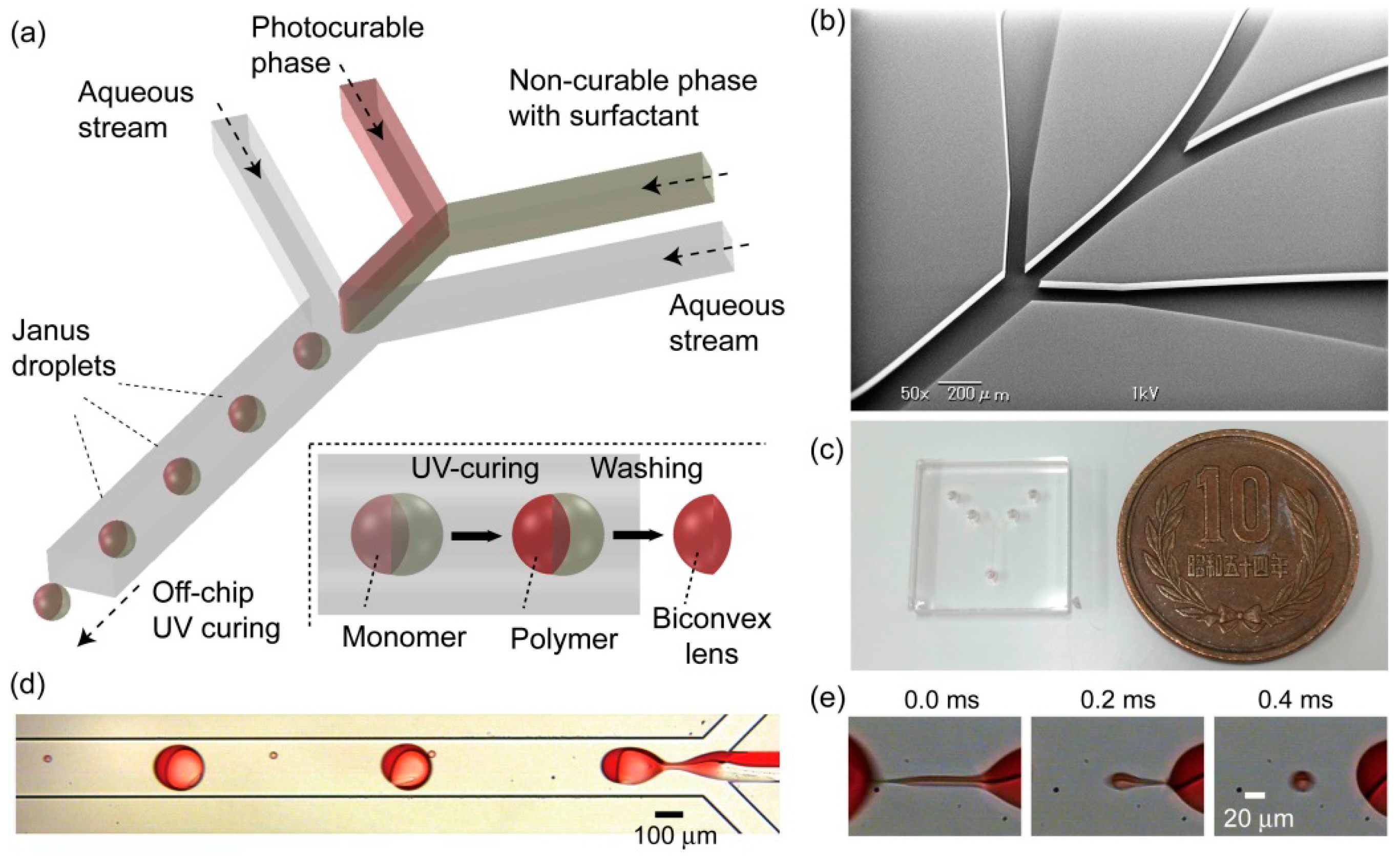
Figure 1d shows the formation of biphasic Janus droplets with the silicone oil carrying surfactant BY11-030 in a microfluidic channel at a break-off frequency of ~160 Hz. The flow rates of the photocurable and non-curable phases are both 0.5 mL·h
−1 (
i.e.,
Qd = 0.5 mL·h
−1 × 2), and the flow rate of the external aqueous phase is 7.0 mL·h
−1 (
i.e.,
Qc = 3.5 mL·h
−1 × 2). By controlling the flow rates of the organic and aqueous streams appropriately in a low-capillary-number region (
i.e., 10
−3–10
−1), reproducible formation of primary Janus droplets was achieved. Using high-speed video microscopy, the formation of a satellite droplet measuring ~20 μm in diameter was observed from the stable biphasic liquid thread formed immediately before the break-off of a primary droplet (
Figure 1e). Thus, biphasic Janus droplets carrying a surfactant in the non-curable phase were produced in a one-step manner, as observed previously in the formation of surfactant-free Janus droplets [
15].
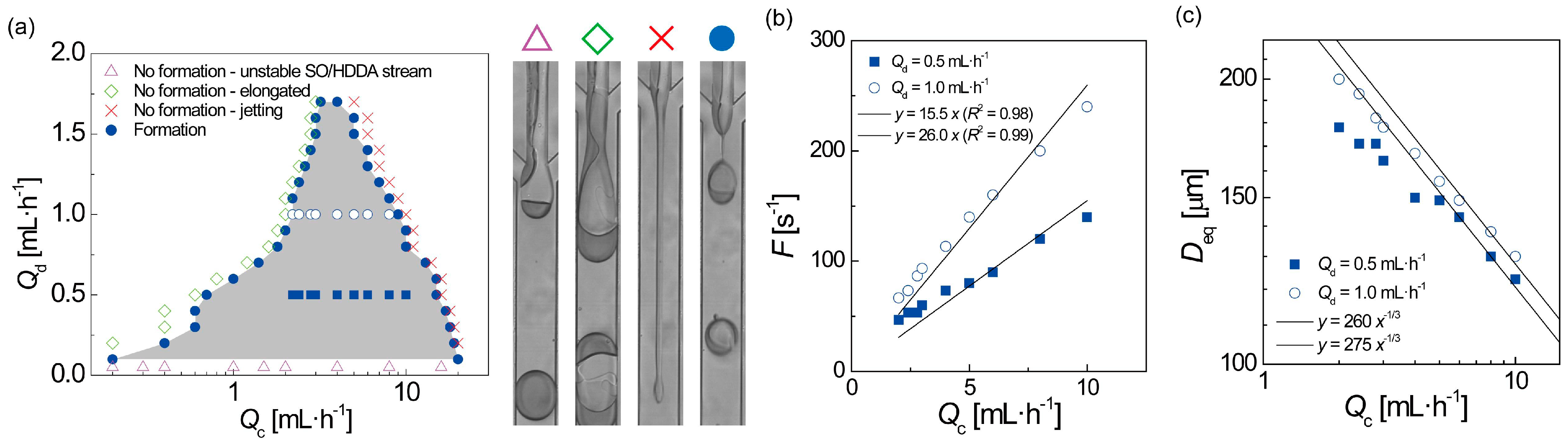
Figure 2a shows a
Qc–
Qd diagram illustrating the flow conditions under which monodisperse Janus droplets can form in our device. The range of
Qc and the maximum throughput
Qd (
i.e., 1.6–1.7 mL·h
−1) were similar to the results previously obtained for surfactant-free Janus droplets, and also to those of a microfluidic device with a similar channel geometry [
15,
19]. Within this region, we adjusted
Qc so as to vary the detachment rate,
Fb, and the size of the Janus droplets.
Fb varied in the range of 50–250 Hz (
Figure 2b), whereas the equivalent diameter of the droplets,
Deq, which is calculated from
Qd and
Fb, varied in the range 120–200 μm (
Figure 2c). These values are consistent with our previous results for a similar microfluidic device [
19].
Figure 2.
Hydrodynamic effects on Janus droplet formation. (a) A Qc–Qd phase diagram illustrating the conditions under which Janus droplets can form. Open circles and solid squares represent conditions under which break-off frequencies were measured, as shown in (b); (b) Measured relationship between Qc and the droplet break-off frequency F; (c) Relationship between Qc and the equivalent diameter of a droplet in a spherical shape, Deq, calculated from F and Qd.
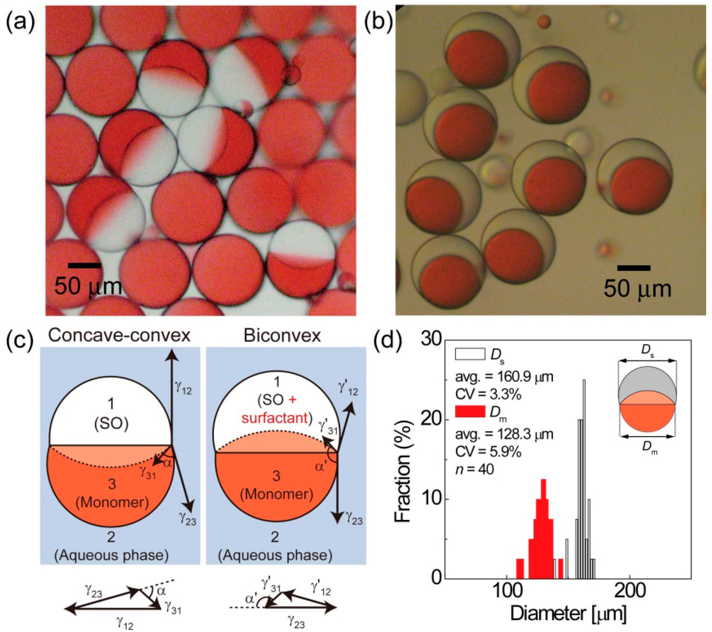
Characterization of the produced droplets was performed in a petri dish off the microfluidic device, thereby allowing us to study the effects of the surfactants in the non-curable silicone oil phase. For the purpose of comparison,
Figure 3a shows a photomicrograph of Janus droplets produced without any surfactant in the non-curable phase. The dyed photocurable segments clearly exhibit a concave-convex shape, with a concave surface at the interface between the two droplet phases. Meanwhile, when we produced Janus droplets with the surfactant BY11-030 in the non-curable phase, the photocurable segment of the produced droplets adopted a biconvex geometry (
Figure 3b). This variation in shape from concave-convex to biconvex can be explained by the shift in balance between the three interfacial tensions, which is mainly caused by the reduced interfacial tension at the interface between silicone oil and water due to the surfactant in the silicone oil segment (
Figure 3c).
The aperture diameters of the photocurable and non-curable segments were measured from the acquired images; the values of the coefficient of variation (CV) were 5.9% and 3.3%, respectively (
Figure 3d), which were similar to our previous results [
19]. Similarly, another surfactant, KF-6015, was added in the non-curable phase and was tested under the same flow conditions. We found that the resultant droplets exhibited a Janus geometry with a similar biconvex shape; the values of the CV for the measured diameters of two segments of the droplets were 3.9% and 3.4% for photocurable and non-curable segments, respectively (see
electronic supplementary information (ESI),
Figure S1). Thus, both surfactants were capable of forming Janus droplets with biconvex photocurable segments.
Figure 3.
Janus droplets off the microfluidic chip. (a) Janus droplets without surfactant in the non-curable silicone oil (SO) segments; (b) Janus droplets with 0.1 wt % BY11-030 surfactant in the non-curable phase; (c) Balance of three interfacial tensions and Neumann’s triangles to form concave-convex and biconvex monomer segments; (d) The distributions of the sizes of two segments, Ds and Dm (see inset) of the Janus droplets in (b).
3.2. Photofabrication of Biconvex Polymer Lenses and Control of Their Shapes by Flow Rate Ratio
Photopolymerization was carried out to produce biconvex microlenses from the Janus droplets with biconvex photocurable segments. In the experiments, UV light was irradiated directly to the end of the drain tube, from which precursor Janus droplets continuously emerged.
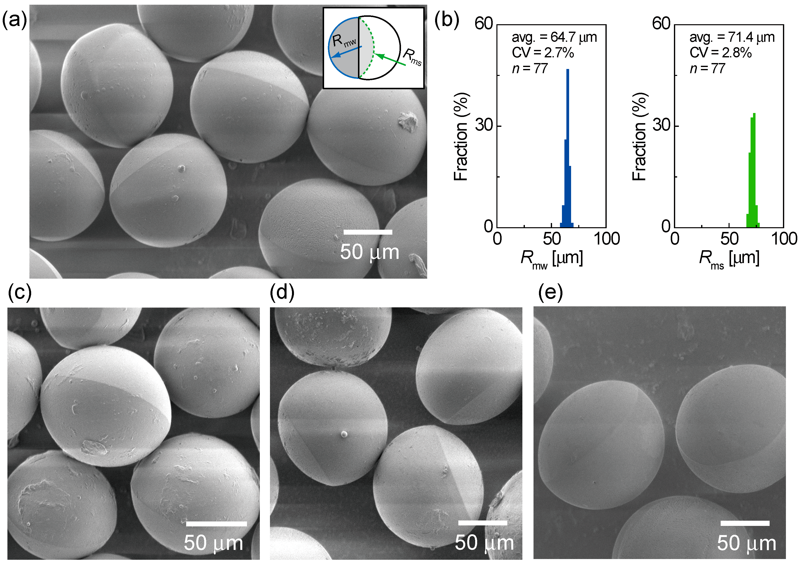
Figure 4a shows a scanning electron microscopy (SEM) image of the microlenses polymerized from Janus droplets with the BY11-030 surfactant, generated at the flow-rate ratio
Qm/
Qs = 1/1, where
Qm and
Qs are the flow rates of the monomer and silicone oil, respectively. The particles clearly have a biconvex shape. The lenses were slightly smaller than the monomer segments of the Janus droplets, possibly due to shrinkage induced by photopolymerization. The two radii of curvature of the biconvex microlenses were measured by image analysis, and were shown to be uniform (
Figure 4b). At this stage, we also varied
Qm/
Qs in the range from 1/2 to 4/1 in order to produce Janus droplets with different volume ratios, thereby producing biconvex particles with different shapes (
Figure 4c–e). The debris and impurities on the lens surfaces can be removed further by repeating washing. Similar photopolymerization was performed on the Janus droplets with the KF-6015 surfactant, and biconvex polymer microlenses were produced with uniform curvatures (ESI,
Figure S2).
Figure 4.
Polymerized biconvex particles. (a) Biconvex particles prepared with 0.1 wt % BY11-030, generated at the flow-rate ratio Qm/Qs = 1/1, where Qm and Qs are the flow rates of the monomer and silicone oil, respectively; (b) The distributions of the two radii of curvature, Rmw and Rms (see inset in (a)); (c–e) Biconvex particles prepared at (c) Qm/Qs = 1/2, (d) Qm/Qs = 2/1, and (e) Qm/Qs = 4/1.
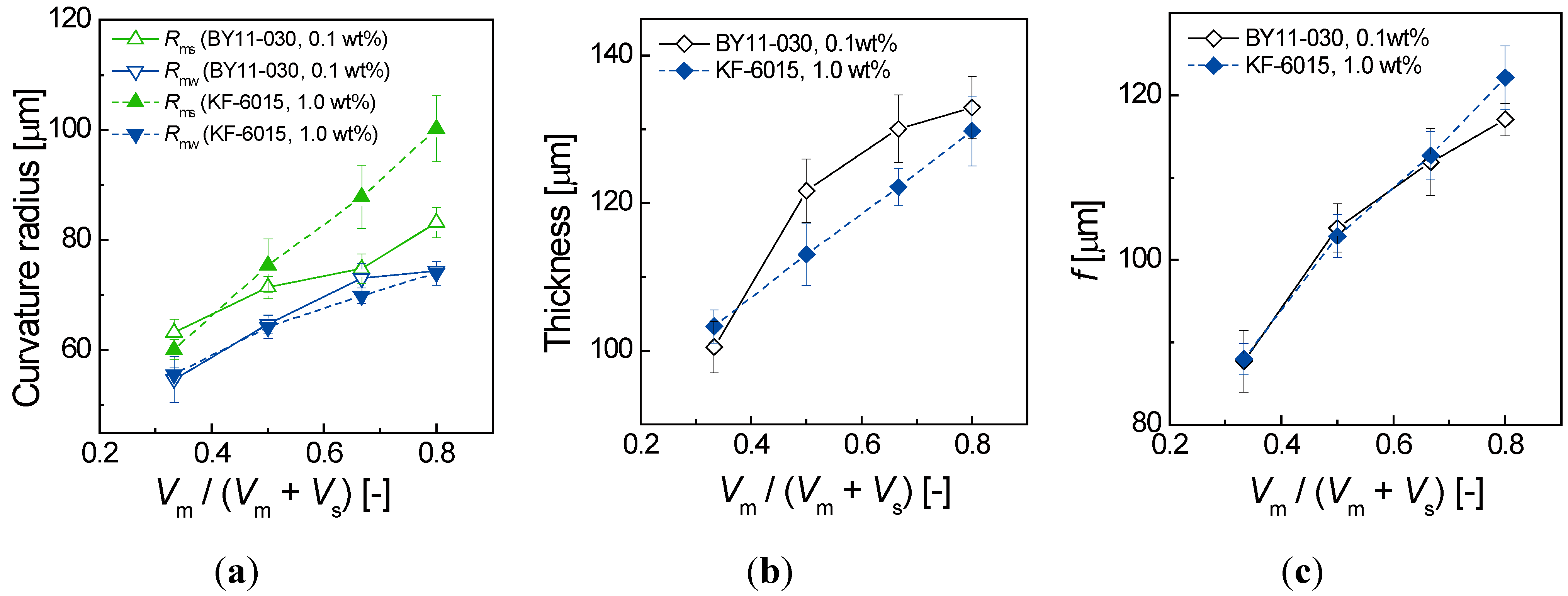
Figure 5a shows the relation between the volume ratio of the two segments (
i.e., the flow-rate ratio of the two droplet phases) and the measured radii of curvature of the produced biconvex particles. We set the flow-rate ratio of the photocurable and non-curable phases
Qm/
Qs as 1/2, 1/1, 2/1 and 4/1. As shown in the graph, all the radii of curvature increased as the ratio of the monomer phase increased. Additionally, in all flow-rate ratios studied, the radius of curvature
Rms, which is the radius of the former monomer/silicone-oil interface, is always larger than
Rmw, which is the radius of the former monomer/water interface. For the microlenses produced with the BY11-030 surfactant, the difference between the two radii of curvature is small, whereas the microlenses produced with the KF-6015 surfactant gave rise to largely different radii of curvatures.
Figure 5b shows the relation between the volume ratio and the thickness of the biconvex particles. As estimated intuitively, the thickness increases as the ratio of the photocurable monomer phase increases.
The focal length
f of a biconvex lens can be determined by using the two radii of curvature, the thickness, and the refractive index of the lens medium according to the following lens maker’s Equation [
21]:
where
n is the refractive index of the lens medium (in this case
n = 1.456),
d is the thickness of the lens, and
R1 and
R2 are the radii of curvature of the lens where light enters and exits, respectively.
Figure 5c shows the relation between the volume ratio and the focal length of the prepared lenses (
Figure 4 and
Figure S2), as calculated by Equation (1). In BY11-030 lenses, the focal length increased from 88 to 117 μm when the volume ratio
Qm/
Qs increased from 1/2 to 4/1. In KF-6015 lenses, the focal length similarly increased from 88 to 122 μm. Thus, the difference in radii of curvatures given by the two surfactants did not significantly affect the shifts in the focal length. The numerical apertures of the prepared lenses are in the range from 0.41 to 0.57, based on NA =
DL/2
f, where NA is the numerical aperture and
DL is the effective lens diameter (~100 μm). The calculated optical resolutions of the lenses range from 0.59 to 0.82 μm, based on δ = 0.61 λ/NA, where δ is the optical resolution of the lens, λ is the wavelength of light (= 550 nm).
Figure 5.
Effect of volume ratios of Janus segments on the measured dimensions of biconvex microlenses and calculated focal lengths. (a) Radius of curvature as a function of the volume ratio; (b) Lens thickness as a function of the volume ratio; (c) Focal length f as a function of the volume ratio. Vm and Vs are the volumes of the monomer and silicone oil segments of the Janus droplets, respectively (i.e., Vm/Vs = Qm/Qs).
3.3. Image Projection Experiments Using Biconvex Polymer Microlenses
We used the prepared biconvex microlenses with different shapes in simple projection experiments to observe how the variation in shape affects the imaging properties of the lenses.
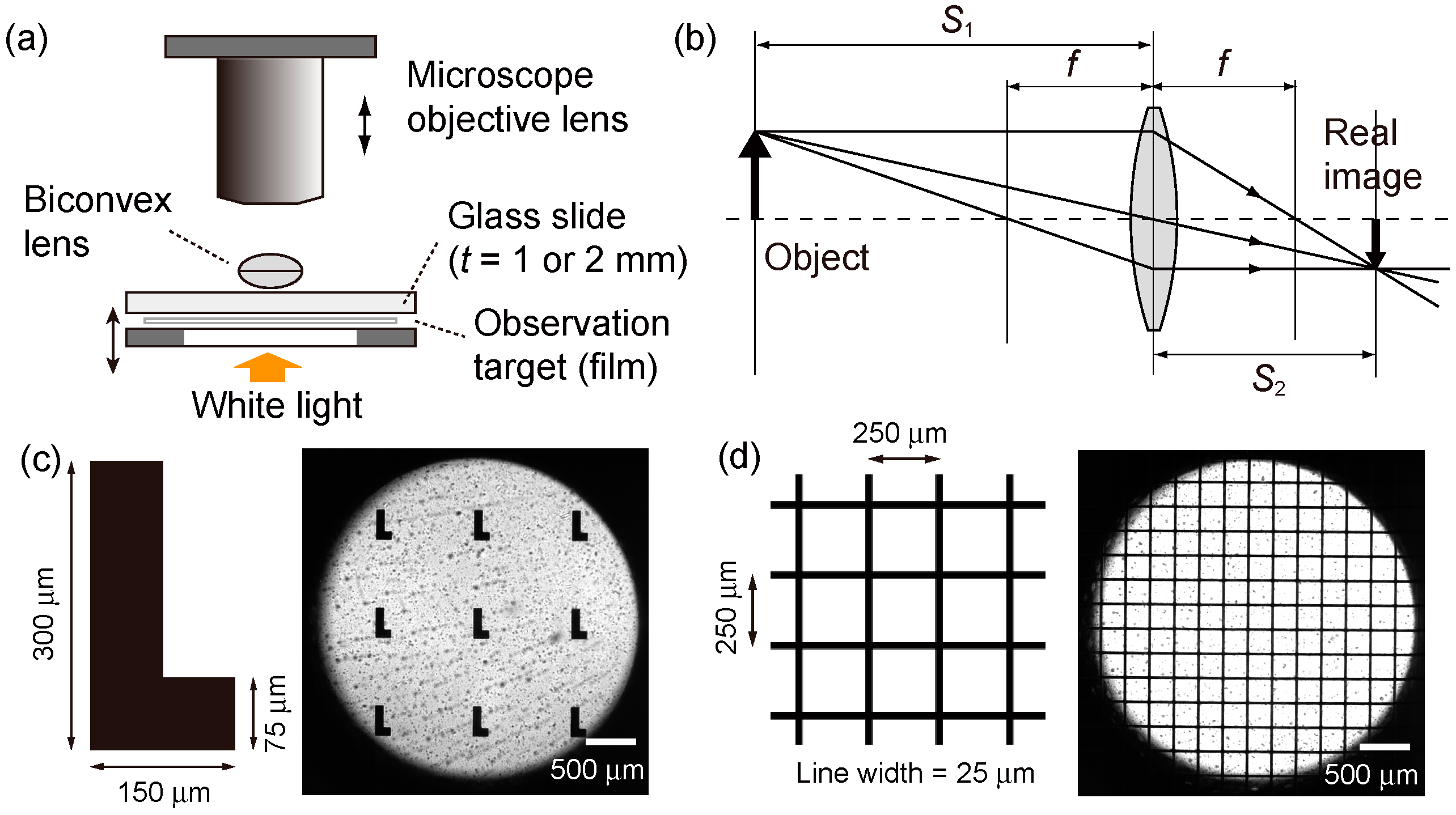
Figure 6a shows the experimental setup for this imaging test. The prepared biconvex microlenses were placed on a transparent quartz glass slide (thickness of 1 or 2 mm), under which a thin photomask film with microprinted patterns was inserted as the imaging object. In this setup, because the distance from the target to the lens,
S1, is well beyond the focal length of the lenses,
f (= 88–122 μm), the real image should be projected on the phase plane at a distance
S2 from the lens in an inverted orientation (
Figure 6b). Therefore, in order to identify the image inversion, we printed black micro “L”-shaped patterns (
Figure 6c) on the photomask as well as mesh patterns (
Figure 6d).
Figure 6.
Schematic diagram of the image projection experiments with the prepared biconvex polymer microlenses. (a) A schematic illustration of the experimental setup; (b) The path of light through a biconvex lens when an object is placed beyond the focal point of the lens; (c) “L”-shaped patterns and (d) a mesh pattern, printed on a thin, transparent polyethylene terephthalate (PET) photomask film.
By moving the focus of the microscope’s 50× objective lens on the phase plane, which was positioned slightly above the microlenses (~100 μm), we were able to find the images projected by the microlenses.
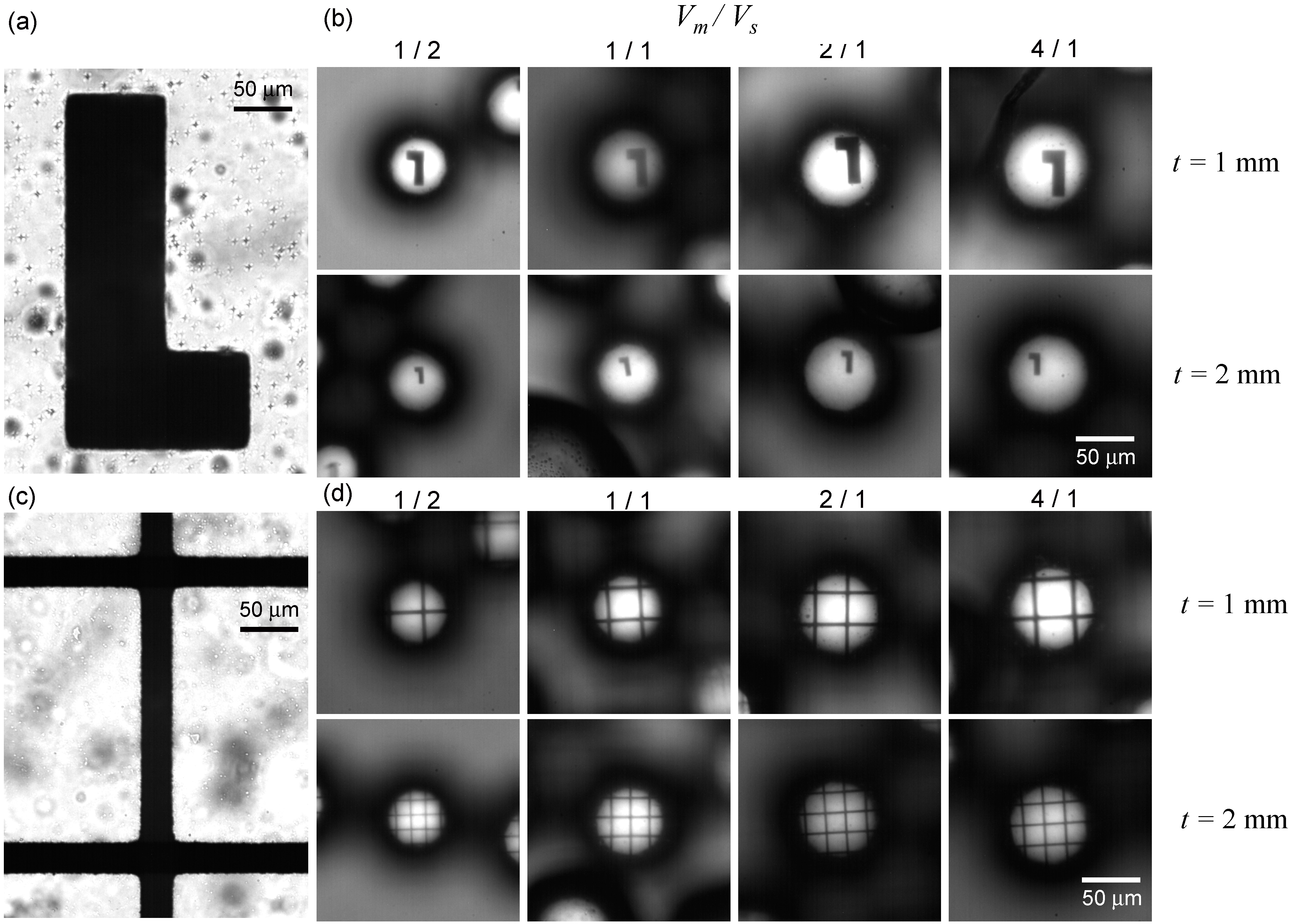
Figure 7b shows images viewed through biconvex lenses of different curvatures on glass slides with thicknesses of 1 or 2 mm. The miniaturized and inverted “L”-shaped pattern (as compared to the original pattern on the photomask film (
Figure 7a)) was observed in all cases. In addition, we found a tendency for the magnification (
i.e., the size of the projected image) to slightly increase as the volume ratio
Vm/
Vs of precursor droplets increased. In addition, the images projected by the lenses at
t = 2 mm were smaller than the images projected by the lenses at
t = 1 mm. Around the edge of the projected area, a slight distortion of the formed pattern was observed; this is probably image distortion, known as one of the monochromatic aberrations [
21]. These characteristics were also observed as slight pincushion distortions when the mesh pattern was viewed through the lenses (
Figure 7c,d). Due to this aberration on the edge of the lenses, it is desirable to align the object in the center of optical axis. Certainly, the microlenses also have spherical aberration along the optical axis, which is another monochromatic aberration and is typical in spherical lenses.
From
Figure 6b, the magnification factor
M, which is defined as the ratio of the size of the projected image to the size of the object, can be expressed by two independent parameters—the distance from the lens to the object,
S1, and the focal length,
f—as follows:
this equation implies that a longer
S1 produces a more reduced image, thus explaining why the lenses at
t = 2 mm produced smaller images compared to those of the lenses at
t = 1 mm, as shown in
Figure 7. Equation (2) also explains why a biconvex lens with longer focal length results in a higher magnification when
S1 is fixed. This explains why the size of the projected image increases as the volume ratio of precursor Janus droplets increases; more specifically, as shown in
Figure 5c, the focal length of the lenses increases as the volume ratio increases.
Figure 7.
Observation of micro-printed patterns projected through BY11-030 biconvex microlenses positioned at two different distances. (a,b) Observation of the “L”-shaped pattern through the lenses of four different shapes; (c,d) Observation of the mesh pattern through the lenses.
Figure 7.
Observation of micro-printed patterns projected through BY11-030 biconvex microlenses positioned at two different distances. (a,b) Observation of the “L”-shaped pattern through the lenses of four different shapes; (c,d) Observation of the mesh pattern through the lenses.
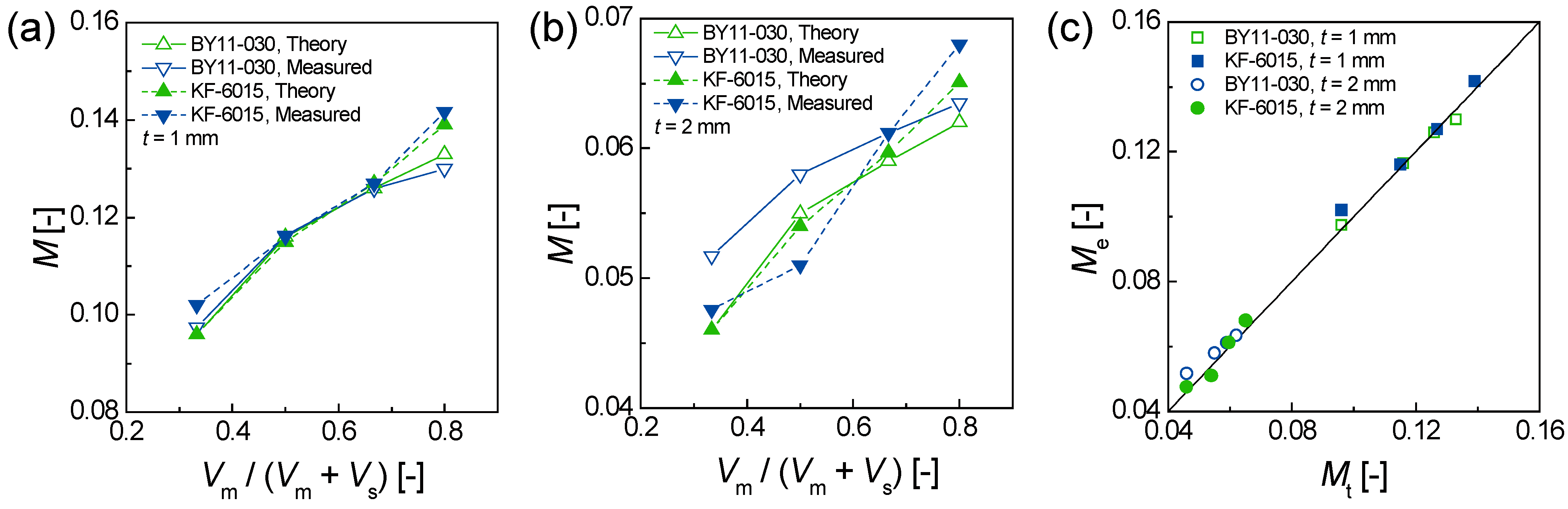
Using the biconvex lenses prepared from Janus droplets of different volume ratios, we measured the magnification
M through the lenses by comparing the sizes of the objects against the formed real images.
Figure 8a shows the relation between the volume ratios of the precursor Janus droplets and the magnification
M calculated theoretically (with
f and
S1 using Equation (2)) and measured experimentally when the lenses are placed on the glass slide with a thickness of 1 mm. The magnification coefficients increase in the range of 0.096–0.133 as the volume ratio increases for BY11-030 lenses; for KF-6015 lenses (ESI,
Figure S3), the magnification increases in the range of 0.096–0.142 as the volume ratio increases. When
S1 = 2 mm,
M varies in the lower magnification range of 0.046–0.063 for BY11-030 lenses, and 0.046–0.068 for KF-6015 lenses; in either case,
M increases as the volume ratio increases (
Figure 8b). For both BY11-030 and KF-6015 lenses, the theoretically estimated magnification
Mt and the experimentally measured magnification
Me match each other well (
Figure 8c). In this way, we demonstrated that by changing the flow-rate ratios, we were able to produce biconvex polymer microlenses with different imaging properties.
Figure 8.
Magnification by the prepared biconvex microlenses. (a,b) Experimentally measured and theoretically calculated magnification of the prepared lenses as a function of the volume ratio of the precursor droplets for (a) t = 1 mm and (b) t = 2 mm; (c) Measured magnification as a function of theoretical magnification.


