A DFT Study on the Adsorption of H2S and SO2 on Ni Doped MoS2 Monolayer


1
College of Engineering and Technology, Southwest University, Chongqing 400715, China
2
State Grid Chongqing Shiqu Power Supply Company, Chongqing 400015, China
*
Author to whom correspondence should be addressed.
Nanomaterials 2018, 8(9), 646; https://doi.org/10.3390/nano8090646
Submission received: 23 July 2018
/
Revised: 8 August 2018
/
Accepted: 14 August 2018
/
Published: 22 August 2018
Abstract
:In this paper, a Ni-doped MoS2 monolayer (Ni-MoS2) has been proposed as a novel gas adsorbent to be used in SF6-insulated equipment. Based on the first-principles calculation, the adsorption properties of Ni-MoS2 to SO2 and H2S molecules, the main decomposition components of SF6 under a partial discharge (PD) condition have been studied. The adsorption energy, charge transfer, and structural parameters have been analyzed to find the most stable gas-adsorbed Ni-MoS2. Furthermore, the density of states (DOS), projected density of states (PDOS), and electron density difference were employed to explore the interaction mechanism between SO2, H2S, and the Ni-MoS2 surface. It is found that the H2S molecule and SO2 molecule interact with the Ni-MoS2 surface by strong adsorption energy. Therefore, we conclude that the interaction between these two kinds of gases and the Ni-MoS2 monolayer belongs to chemisorption, and the Ni-MoS2 monolayer might be a promising gas adsorbent for the fault recovery of SF6-insulated equipment. Additionally, we have to point out that all of the conclusions only considered the final adsorption energy, the barrier in the transition state has not been analyzed in this paper.
1. Introduction
Due to the excellent insulation and arc extinguishing properties of SF6, it has obtained a wide application in gas-insulated equipment, such as gas-insulated switchgear (GIS), gas-insulated breaker (GIB), and gas-insulated transformer (GIT). In addition, SF6-insulated equipment exhibits a great deal of advantages, such as a small occupied area requirement, little electromagnetic pollution, and high safety and reliability [1,2]. However, a certain amount of insulation defects inevitably occur in SF6-insulated equipment during the long-term running process, which may lead to partial discharge (PD) and the decomposition from SF6 to SFx under the operating voltage [3,4]. Simultaneously, the SF6 gas-filled chamber inevitably contains trace amounts of impurities, such as H2O and O2 [5]. SFx will quickly react with the H2O and O2 into various decomposition components (such as H2S, SO2, SOF4, SO2F2, SOF2, HF, CF4, and CO2, etc.) [1,6,7,8]. These decomposition components can significantly accelerate the corrosion and aging process of the insulation medium, resulting in insulation failure. In order to ensure the running stability of SF6-insulated equipment, the primary task is to maintain the purity of the filling gas, namely removing the decomposition components of SF6 [9,10]. Considering all of the SF6 decomposition components, H2S, SO2 gases, the main decomposition components under all types of PD conditions are the key removing target gases [11,12,13]. Thus, it is urgent to explore an effective adsorbent for H2S and SO2 removal.
Recently, along with the upsurge of research on graphene and other two-dimensional (2D) layered nanomaterials [14,15,16], the graphene-like MoS2 monolayer, exhibiting good chemical stability and thermal stability, high specific surface area, and high surface activity, has attracted much research interest for various applications, including electrochemical lithium storage, solid lubrication, catalysis, and gas adsorbents [17,18,19,20,21,22]. Among them, the application of MoS2 in gas adsorption has attracted much research attention in recent years. Liu et al. developed an ethanol gas sensor based on an indium oxide/molybdenum disulfide (In2O3/MoS2) nanocomposite, and investigated its gas-sensing properties to ethanol gas [23]. Dongwei Ma et al. improved the sensing properties of MoS2 to CO and NO by doping the MoS2 monolayer with Au, Pt, Pd, and Ni, concluding that introducing appropriate dopants could be a feasible method to improve the gas sensing performance of MoS2-based gas sensors [24]. The gas adsorption properties of common gases (CO, NO2, H2O, NH3) on a pristine monolayer MoS2 and a metal (V, Nb, Ta)-doped MoS2 monolayer reported by Jia Zhu et al., indicated that metal doping can significantly improve the adsorption properties, chemical activity, and sensitivity of the MoS2 monolayer [25].
On the one hand, metal atom doping provides a large number of free electrons, namely improving the electrical conductivity of the MoS2 monolayer. On the other hand, the strong orbital hybridization between the metal atom and gas molecules enhances the gas adsorption capacity of the MoS2 monolayer to gas molecules [24,25,26,27]. Herein, based on the first-principles calculation, we present an extensive theoretical investigation of the structure, total density of states (TDOS), and projected density of states (PDOS) of a Ni-doped MoS2 monolayer. Additionally, its gas adsorption performance towards the typical SF6 decomposition components H2S and SO2 has been systematically studied based on the analysis of structural parameters, TDOS, PDOS, and electron density difference. Furthermore, the gas adsorption mechanisms of the Ni-doped MoS2 monolayer to H2S and SO2 was obtained based on the research above. In order to ensure the practicability of the adsorbent, the adsorption property of the Ni-MoS2 monolayer towards SF6 molecule has also been studied. In conclusion, the Ni-doped MoS2 monolayer shows an ideal adsorption property to the target gases, signifying that it is a promising novel gas adsorbent used to ensure the running stability of SF6-insulated equipment.
2. Computational Details
All calculations were performed based on the density functional theory (DFT) [28,29]. The generalized gradient approximation (GGA) with the Perdew-Burke-Ernzerhof (PBE) was chosen to calculate the geometry optimization with the energy convergence accuracy, maximum stress, and max displacement set to 1 × 10⁻⁵ Ha, 2 × 10⁻³ Ha/Å, and 5 × 10⁻³ Ha, respectively [30,31]. The effect of spin-polarization was ignored in this paper, and Grimme dispersion correction has been introduced to describe the weak interactions, like van der Waals force. The double numerical plus polarization (DNP) was chosen as the basis set, the density functional semi-core pseudopotential (DSPP) was applied in core treatment, and the Monkhorst-pack k point mesh of 5 × 5 × 1 was employed [32,33]. The self-consistent (SCF) field tolerance was set to 1 × 10⁻⁶ Ha, and the DIIS size was set to 6 to speed up the convergence of SCF [34].
A 4 × 4 × 1 MoS2 monolayer supercell with a 20 Å vacuum slab, including 32 S atoms and 16 Mo atoms, was built in order to avoid the interaction between the adjacent cells. The optimized lattice constant of MoS2 is calculated to be 3.180 Å, which is in good agreement with other theoretical calculation results [35]. One Ni atom was placed on the top site of the Mo atom at the center of the 4 × 4 × 1 MoS2 monolayer supercell, bonding with three S atoms.
The adsorption energy (Eads) was calculated by Equation (1) [36]:
where ENi-MoS2/gas is the total energy of the gas adsorbed Ni-MoS2, while ENi-MoS2 and Egas represent the total energy of the Ni-MoS2 monolayer and the total energy of free gas molecule, respectively. The more negative Eads obtained after geometry optimization, the easier for the free gas molecule to be adsorbed on the Ni-MoS2 monolayer surface, indicating the adsorption system is more stable.
Eads = ENi-MoS2/gas − ENi-MoS2 − Egas
In addition, the charge transfer (Qt) between the gas molecule and Ni-MoS2 monolayer was calculated by Equation (2):
where Qa and Qb represent the amounts of carried charge of the gas molecules after and before gas adsorption, which were calculated by electron population analysis [37]. It is worth putting out that the value of Qb is always 0 e in this paper. According to the definition, if Qt is positive, the electrons transfer from gas molecule to the Ni-MoS2 monolayer. Additionally, the density of states (DOS) was calculated to analyze the interaction mechanism between gas molecules and the Ni-MoS2 monolayer [38].
Qt = Qa − Qb
3. Results and Discussion
3.1. Structures and Electronic Properties of H2S, SO2 and the Ni-MoS2 Monolayer
Firstly, the adsorption property of the Ni atom on the MoS2 monolayer was discussed according to the adsorption energy analysis and population analysis. The adsorption energy (Eads) of Ni atom on MoS2 monolayer was defined in the Equation (3):
Eads = ENi-MoS2 − ENi − EMoS2
The negative Eads in Equation (3) indicates that the binding process is exothermic. As the most stable doping position of Ni on MoS2 monolayer is the top site of the Mo atom according to previous studies [24], therefore, only the structure of Ni-MoS2 with Ni doping on the top site of the Mo is discussed in this paper.
As shown in Figure 1, The Ni atom above the Mo3 atom bonds with other three surrounding S atoms with a length of 2.121 Å, and there is no chemical bond between the doped Ni atom and the Mo3 atom because of the long distance between them (2.596 Å). The bond angle of the Mo1-S1-Mo2 near the Ni atom (81.3°) has slightly changed compared with that of the MoS2 monolayer without doping (82.0°), indicating that the doped Ni atoms have a strong interaction with the initial MoS2 monolayer structure, and the doping structure could be quite stable. Moreover, the large binding energy (3.495 eV) further confirmed the conclusion above. In addition, the charge transfer from the Ni atom to the MoS2 monolayer is 0.021 e.
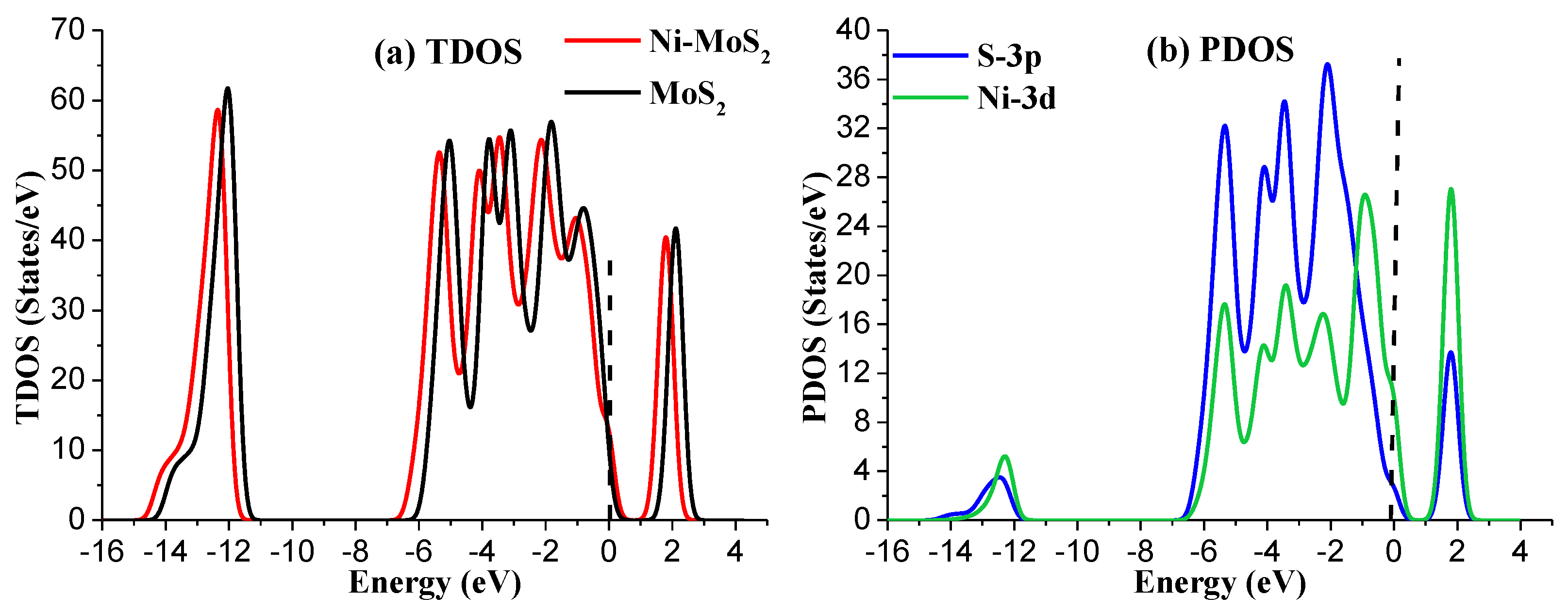
To further analyze the structural properties of Ni-MoS2 monolayer, the total density of states (TDOS) and projected density of states (PDOS) have been calculated as shown in Figure 2. For TDOS distribution, the electron distribution of the Ni-MoS2 monolayer around the Fermi level has slightly increased compared with that of the MoS2 monolayer, implying that the doping of the Ni atom has enhanced the metallic property of the MoS2 monolayer. As a result, the doped Ni atom acts as the active site for building interaction between the Ni-MoS2 monolayer and the target gas molecules. For PDOS distribution, the peaks of Ni-3d orbital and S-3p orbital overlap at −5.5 eV, −4.5 eV, −3.5 eV, −2.5 eV, and 2.0 eV, indicating that the S-3p orbital strongly hybridize with the Ni-3d orbital. Therefore, the Ni atom adsorbs on the surface of MoS2 monolayer by a stable structure.
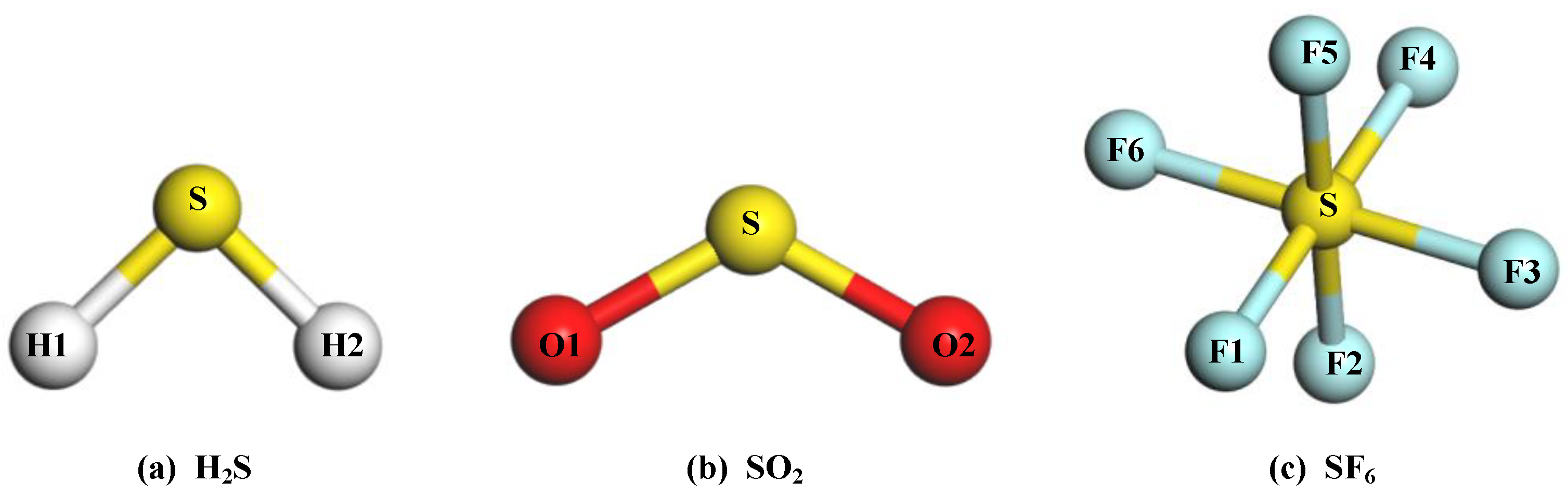
The structures of the gas molecules are exhibited in Figure 3, and its specific structural parameters of the gas molecules are listed in Table 1. Additionally, the carried charge of S and O atom in the SO2 are 0.453 e and −0.227 e, respectively. The H atom in the H2S has a positive charge of 0.174 e, and the S atom has a negative charge of 0.348 e. For the SF6 molecule, the charge of the S atom is calculated to be 1.194 e, and the F atom is −0.199 e. These results are in agreement with the other theoretical calculation reports [39].
3.2. Adsorption of H2S Gas on the Ni-MoS2 Monolayer
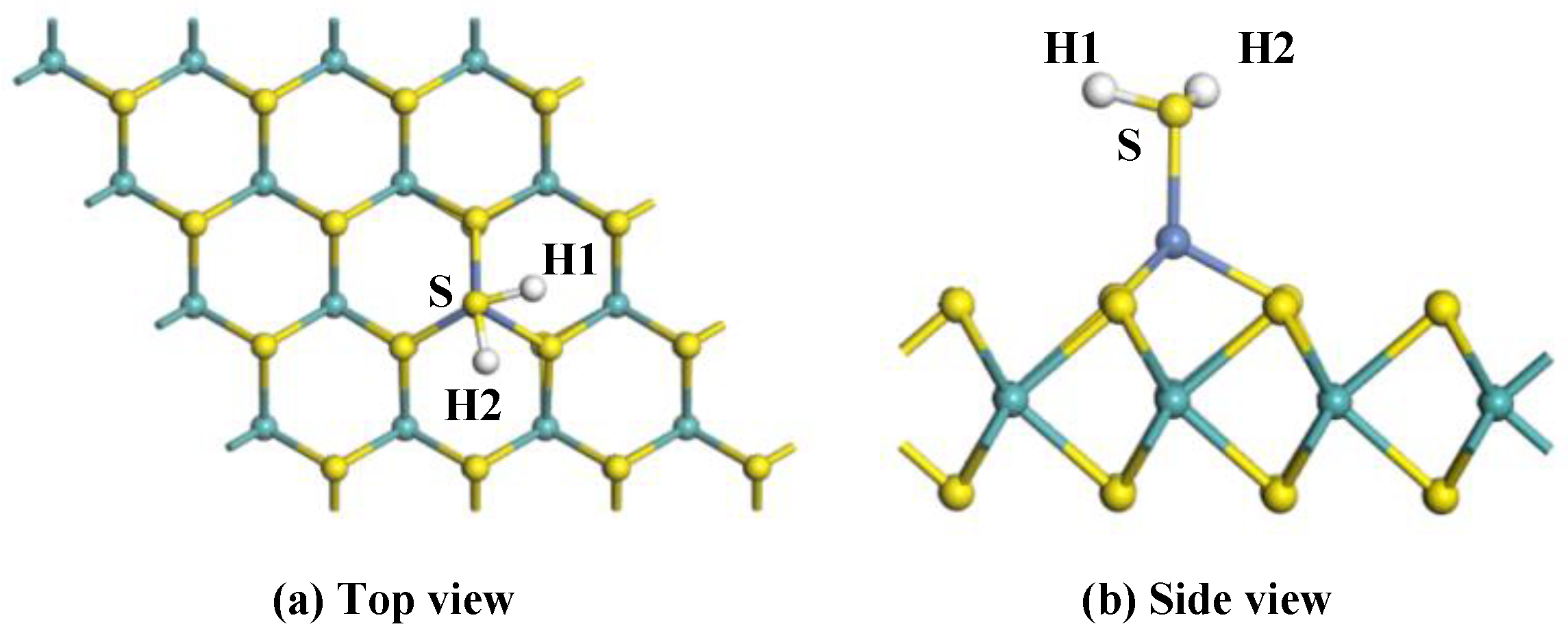
To analyze the adsorption properties of Ni-MoS2 monolayer to the target gas molecules, various initial approaching sites of H2S to the Ni-MoS2 monolayer were calculated in order to obtain the most stable adsorption structure. After optimization, only one typical adsorption structure was received, as shown in Figure 4 in the top view and side view, and its Eads, Qt, and specific structure parameters are shown in Table 2.
For adsorption system with structure shown in Figure 4a,b, a Ni-S bond with a length of 2.205 Å forms in the adsorption process, and the amount of the electrons transferred from the H2S molecule to Ni-MoS2 monolayer is up to 0.254 e, which means the S-Ni bond is not easy to break. However, the structure of the H2S has slightly changed after adsorption. The length of the H-S bond increases to 1.362 Å, the angle of the H1-S-H2 turned into 91.5°. The Eads of H2S on the Ni-MoS2 monolayer is −1.319 eV, which is large enough to completely adsorb H2S. Though barrier exists in the transition state, but the change of the structure of H2S is not obvious, therefore, we conclude that the large Eads can provide the energy to cross over the barrier. As a result, from the amount of electrons transfer and Eads, we conclude that the structure is the most stable structure for H2S adsorption.
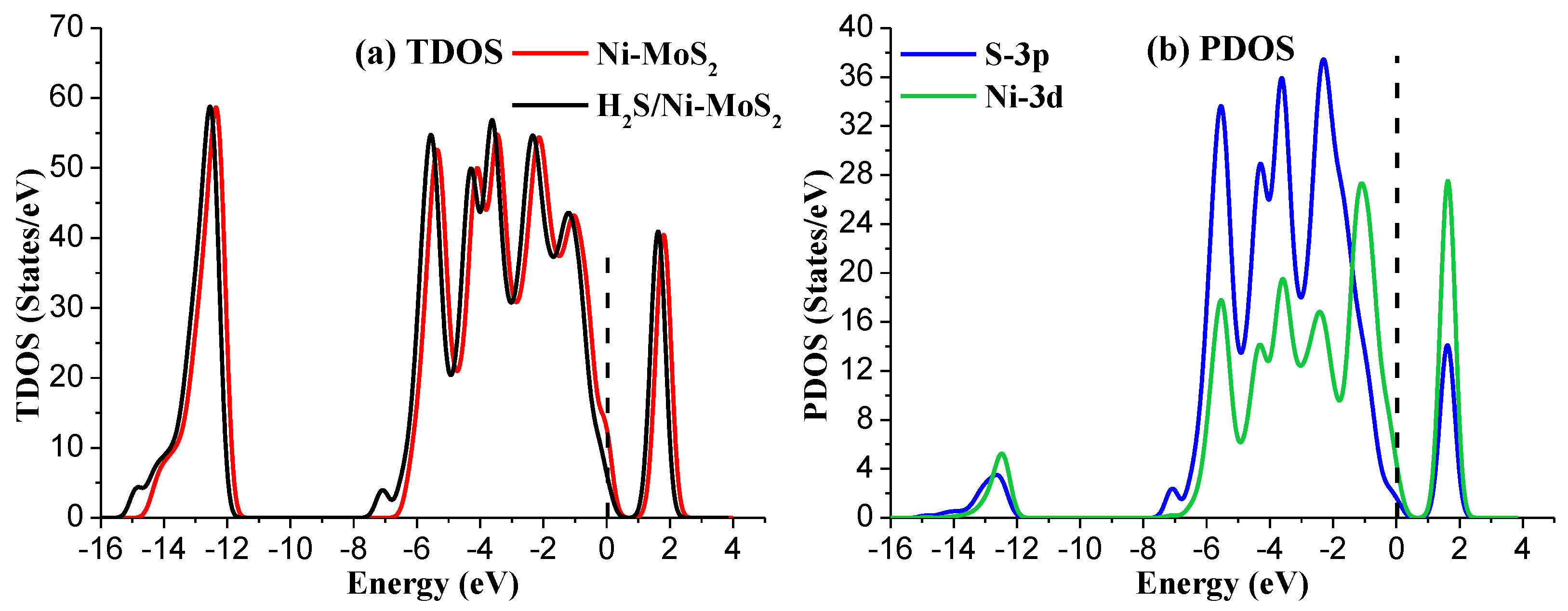
Figure 5 presents the TDOS and PDOS of Ni-MoS2 monolayer before and after H2S molecule adsorption. The TDOS after H2S molecule adsorption shows a significant increase near −7 eV and −15 eV. Due to the main contribution of the outer orbitals of interacted atom in the adsorption process, only the PDOS of the S-3p and Ni-3d was discussed. The PDOS analysis shows that the S-3p orbitals overlaps with the Ni-3d orbitals in the range from −6 eV to 0 eV, and the overlapped peaks of these two orbitals appear at about −5 eV, −4 eV, −3.5 eV, −2.5 eV, and 1 5 eV. The wide range of overlap fully verifies the strong hybridization between these two orbitals. The analysis of TDOS and PDOS furtherly confirms the strong interaction between H2S and Ni-MoS2 monolayer, and its structure is quite stable.
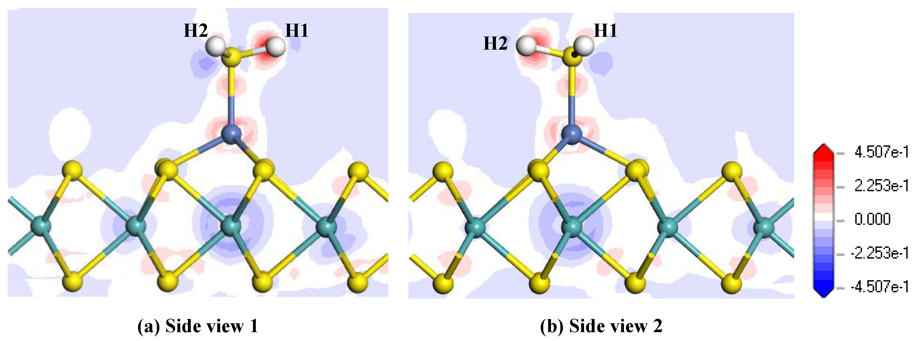
Figure 6 shows the electron density difference of the H2S adsorbed Ni-MoS2 monolayer from different side views, where the increase and decrease of the electron density are represented by the red and blue region, respectively. From the electron density difference, it is intuitive to analyze the charge distribution after the gas adsorption. It can be found that both of the H atoms receive electrons, while the electron density near the S atom and Ni atom suffer a reduction and increase, respectively, which is in agreement with the conclusion that the H2S molecule transfers quite a number of electrons to the monolayer. It is also interesting to notice that the electron density near the Mo atom below the Ni atom suffers an obvious reduction, and we assume that the electrons from the Mo atom made a contribution to the increase of the electron density surrounding H atoms. Therefore, the H2S molecule brings a dramatic change of electron density to the Ni-MoS2 monolayer.
In conclusion, considering the structure parameters, charge transfer, adsorption energy, DOS, and electron density difference of H2S adsorbed Ni-MoS2 monolayer, it is obvious that the interaction between the H2S and the Ni-MoS2 monolayer belongs to chemisorption. In consequence, this configuration is the most stable adsorption structure for H2S adsorption on a Ni-MoS2 monolayer. The Ni-MoS2 monolayer shows an outstanding adsorption property to H2S molecules.
3.3. Adsorption of SO2 Gas on a Ni-MoS2 Monolayer.
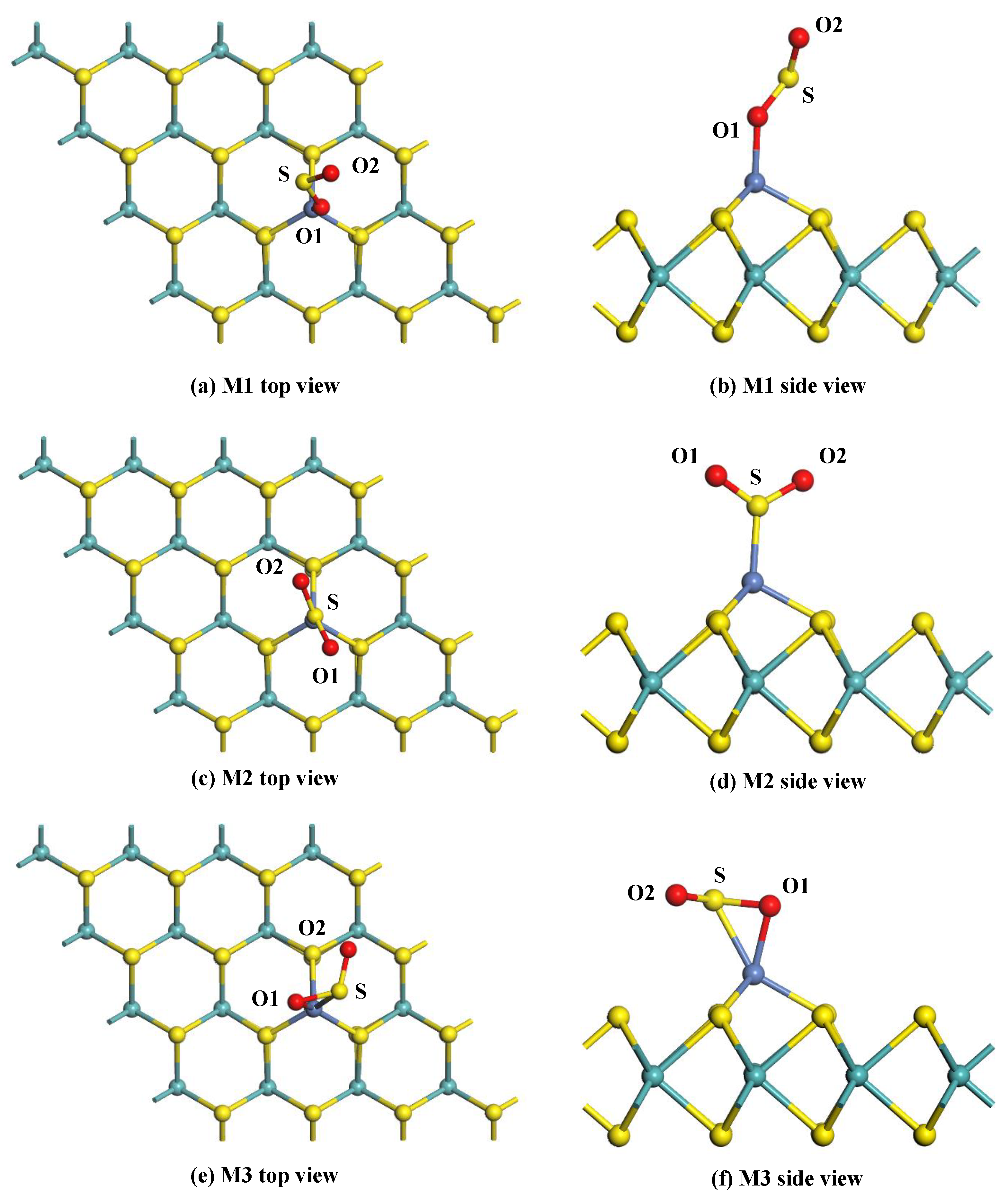
For the adsorption of SO2 gas, the gas molecule is initially placed at various sites to approach the surface of the Ni-MoS2 monolayer. Three typical adsorption structures were obtained after geometric optimization, as shown in Figure 7. Table 3 shows the structural parameters of these configurations.
Figure 7a,b shows the top view and side view of the M1 system. It can be seen that the SO2 molecule adsorbs on the Ni-MoS2 monolayer through the Ni-O1 bond, and the length of the Ni-O1 bond is 1.903 Å. The O1-S bond of SO2 adsorbed on the monolayer is 1.543 Å, which slightly longer than that of a free SO2 molecule (1.480 Å). The angle of the O1-S-O2 has decreased 5°. Thus, the structure of the SO2 molecule changes very little during the adsorption process. The Eads of the M1 system is calculated to be −0.823 eV, 0.094 e transfers from the Ni-MoS2 monolayer to the SO2 molecule. Due to the strong interaction between SO2 and the Ni-MoS2 monolayer, the adsorption of the M1 system belongs to chemisorption.
The top view and side view of the M2 system are given in Figure 7c,d, the SO2 molecule adsorbs on the monolayer with a Ni-S bond length of 2.059 Å. From the structural parameters in Table 3, it is found that the structure of the SO2 molecule changes little after adsorption. The Eads of the M2 system has increased to −1.382 eV compared to that in the M1 system, which manifests the stability of the M2 system. In Addition, only 0.016 e transfers from the SO2 molecule to the Ni-MoS2 monolayer in the M2 system, and the charge transfers from the S atom, O1 atom, and O2 atom are 0.050 e, −0.033 e, and −0.033 e, respectively.
The top view and side view of the M3 system are given in Figure 7e,f, the O1 atom and S atom are trapped by the Ni-MoS2 monolayer with bond lengths of 1.948 Å (Ni-O1) and 2.258 Å (Ni-S). Due to the strong interaction of the Ni-O1 bond and Ni-S bond, the Qt of the M3 system is calculated to be −0.206 e, which is distinctly larger than that in the M1 and M2 system. From the structural parameters in Table 3, the bond distance and angle in the SO2 molecule insignificantly change after adsorption. The Eads of M3 exhibited in Table 3 is −1.327 eV, which is slightly smaller than that in the M2 system.
Above all, according to the large amount of Eads and charge transfer between the SO2 molecule and the M2 system, chemisorption of Ni-MoS2 monolayer to SO2 can be concluded. Although the Eads of M3 system is very close to that of the M2 system, these two new built bonds between the SO2 molecule and Ni atom in M3 system means a higher barrier during the adsorption process. Therefore, the M2 system is the most stable configuration. To further verify the conclusion, the DOS and the electron density difference are intensively discussed below.
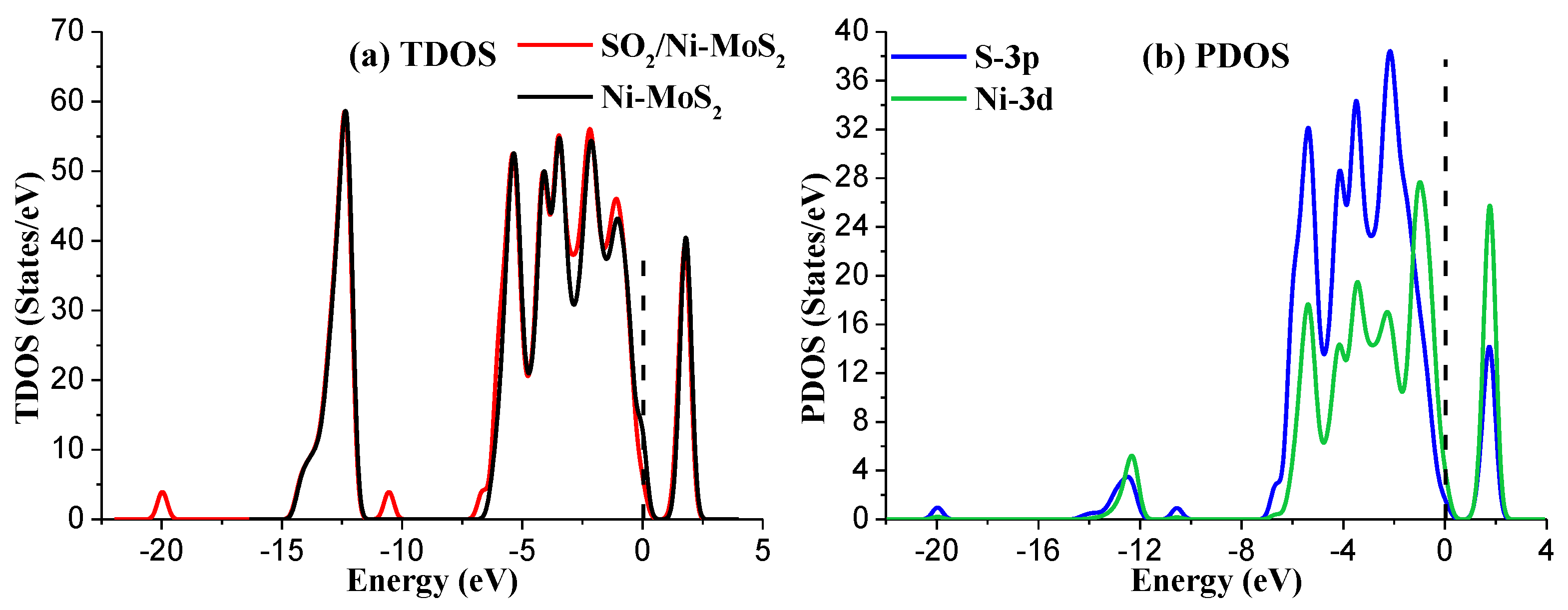
Figure 8a shows the TDOS of the M2 system. It is obvious that a small change occurs in TDOS around the area of −20 eV, −10.5 eV, −7 eV, −3 eV, and −1 eV for the SO2-adsorbed Ni-MoS2 monolayer. Similarly, as the adsorption process mainly contributed by of the outmost orbitals of atoms, only the PDOS of the S-3p and Ni-3d are discussed, as shown in Figure 8b. According to the PDOS results, the peaks of S-3p orbital and the Ni-3d orbital overlap at −5.5 eV, −4 eV, −2 eV, and 2 eV, suggesting that the interaction between SO2 and Ni-MoS2 monolayer is strong chemisorption, and its electronic structures are relatively active. Considering the large contribution of the S-3p orbital in the adsorption process, we confirm that the SO2 adsorption structure in the M2 system is very stable.
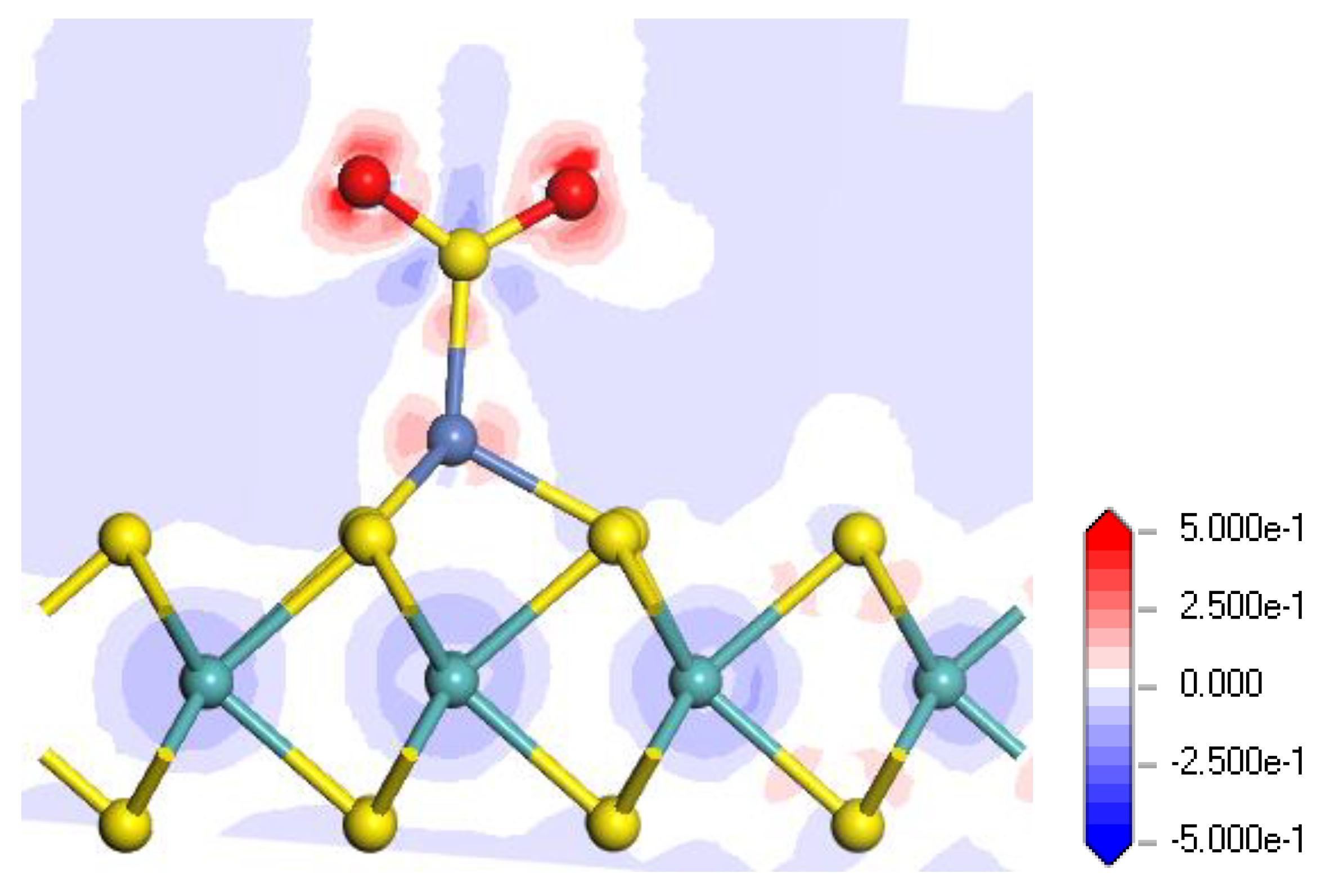
With respect to the electron density difference in the M2 system, shown in Figure 9, the increase and decrease of the electron density are represented by the red and blue regions, respectively. It is found that two O atoms in SO2 receive electrons, and the electron density near the S atom decreases during the adsorption. In generally, the SO2 molecule acts as an electron acceptor according to the electron density distribution.
3.4. Adsorption of SF6 Gas on the Ni-MoS2 Monolayer
In order to ensure the practicability of the Ni-MoS2 adsorbent, the adsorption property of the Ni-MoS2 monolayer towards the SF6 molecule has also been studied, as SF6 will always be the largest part of components in SF6-insulated equipment. Various initial approaching sites of SF6 to the Ni-MoS2 monolayer were calculated in order to obtain the most stable adsorption structure. Two adsorption structures were received after geometric optimization, as shown in Figure 10 with different views. In addition, its adsorption energy, charge transfer, and other specific structural parameters are given in Table 4.
As the parameters show in the Table 4, the Eads is only −0.174 eV for M1, and 0.181 eV for M2. Qt is −0.445 e and −0.454 e for the M1 and M2 structures, respectively. Though the dF1-S of SF6 suffers a very small increase compared with that of free SF6 molecule, it is still difficult to break its chemical bonds by the weak adsorption energy. Therefore, the SF6 molecule interacts with Ni-MoS2 monolayer by physisorption. Once H2S and SO2 decomposition components occur in SF6-insulated equipment, H2S and SO2 quickly fill the role of the adsorption of SF6 because of its strong adsorption energy of H2S and SO2. Additionally, the repulsion between gas molecules will block the interaction between the SF6 molecule and Ni-MoS2 monolayer. As a result, the Ni-MoS2 monolayer can be a good adsorbent to H2S and SO2 in a SF6 atmosphere.
4. Conclusions
In this study, a Ni-MoS2 monolayer material has been proposed as a potential adsorbent to remove the typical decomposition components of SF6 under partial electric discharge: H2S and SO2. All of the calculations performed with respect to density functional theory analysis and all of the conclusions only considered the final adsorption energy; the barrier in transition state has not been analyzed in this paper. Various adsorption models of H2S and SO2 molecules on the Ni-MoS2 monolayer were built to find the most stable adsorption structure by analyzing the adsorption energy, charge transfer, and other structural parameters. To further analyze the interaction mechanism, the DOS, PDOS and electron density difference were presented and analyzed. We concluded that H2S and SO2 tend to adsorb on the surface of Ni-MoS2 monolayer by chemisorption, and the adsorption energy of the H2S and SO2 is up to −1.319 eV and −1.382 eV, respectively, indicating that the interaction between these two kinds of gases and the Ni-MoS2 monolayer is pretty strong. Additionally, the weak physisorption between SF6 and the Ni-MoS2 monolayer provides the basis for selectively adsorbing H2S and SO2 from the SF6 atmosphere. Therefore, the Ni-MoS2 monolayer might be a promising gas adsorbent to remove these two typical decomposition components of SF6, which plays a key role in enhancing the running stability of SF6-insulated equipment.
Author Contributions
Y.G. proposed the project and analyzed the simulation results. H.W. and Y.G. contributed to the DFT simulations. J.K., W.W. and C.T. performed the analysis of the data and provided some revision of the manuscript. All authors read and approved the final manuscript.
Funding
This research was funded by the National Key R&D Program of China (grant no. 2017YFB0902700 and no. 2017YBF0902702), and the Fundamental Research Funds for the Central Universities (grant no. SWU118030).
Acknowledgments
This study was supported by the National Key R&D Program of China (grant nos. 2017YFB0902700, 2017YBF0902702), and the Fundamental Research Funds for the Central Universities (grant no. SWU118030).
Conflicts of Interest
The authors declare no conflict of interest.
References
- Fu, Y.; Rong, M.; Yang, K.; Yang, A.; Wang, X.; Gao, Q.; Liu, D.; Murphy, A.B. Calculated rate constants of the chemical reactions involving the main byproducts SO2F, SOF2, SO2F2 of SF6 decomposition in power equipment. J. Phys. D Appl. Phys. 2016, 49, 155502. [Google Scholar] [CrossRef]
- Ren, M.; Dong, M.J.L. Statistical Analysis of partial discharges in SF6 gas via optical detection in various spectral ranges. Energies 2016, 9, 152. [Google Scholar] [CrossRef]
- Fridman, A.; Chirokov, A.; Gutsol, A. Non-thermal atmospheric pressure discharges. J. Phys. D Appl. Phys. 2005, 38, R1. [Google Scholar] [CrossRef]
- Gui, Y.; Zhang, X.; Zhang, Y.; Qiu, Y.; Chen, L. Study on the characteristic decomposition components of air-insulated switchgear cabinet under partial discharge. Aip Adv. 2016, 6, 868–871. [Google Scholar] [CrossRef]
- Zhang, X.; Gui, Y.; Zhang, Y.; Qiu, Y.; Chen, L. Influence of humidity and voltage on characteristic decomposition components under needle-plate discharge model. IEEE Trans. Dielectr. Electr. Insul. 2016, 23, 2633–2640. [Google Scholar] [CrossRef]
- Fu, Y.; Yang, A.; Wang, X.; Murphy, A.B.; Li, X.; Liu, D.; Wu, Y.; Rong, M. Theoretical study of the neutral decomposition of SF6 in the presence of H2O and O2 in discharges in power equipment. J. Phys. D Appl. Phys. 2016, 49, 385203. [Google Scholar] [CrossRef]
- Li, Z.; Chen, S.; Gong, S.; Feng, B.; Zhou, Z. Theoretical study on gas decomposition mechanism of SF6 by quantum chemical calculation. Comput. Theor. Chem. 2016, 1088, 24–31. [Google Scholar] [CrossRef]
- Zeng, F.; Tang, J.; Zhang, X.; Sun, H.; Yao, Q.; Miao, Y. Study on the influence mechanism of trace H2O on SF6 thermal decomposition characteristic components. IEEE Trans. Dielectr. Electr. Insul. 2015, 24, 367–374. [Google Scholar]
- Wilk, A.; Więcław-Solny, L.; Śpiewak, D.; Spietz, T.; Kierzkowska-Pawlak, H. A selection of amine sorbents for CO2 capture from flue gases. Chem. Process Eng. 2015, 36, 49–57. [Google Scholar] [CrossRef]
- Wilk, A.; Więcław-Solny, L.; Tatarczuk, A.; Krótki, A.; Spietz, T.; Chwoła, T. Solvent selection for CO2 capture from gases with high carbon dioxide concentration. Korean J. Chem. Eng. 2017, 34, 2275–2283. [Google Scholar] [CrossRef]
- Tang, J.; Yang, X.; Yang, D.; Yao, Q.; Miao, Y.; Zhang, C.; Zeng, F. Using SF6 decomposed component analysis for the diagnosis of partial discharge severity initiated by free metal particle defect. Energies 2017, 10, 1119. [Google Scholar] [CrossRef]
- Tang, J.; Yang, X.; Yao, Q.; Miao, Y.; She, X.; Zeng, F. Correlation analysis between SF6 decomposed components and negative DC partial discharge strength initiated by needle-plate defect. IEEJ Trans. Electr. Electron. Eng. 2018, 13, 382–389. [Google Scholar] [CrossRef]
- Zhang, X.; Gui, Y.; Dai, Z. A simulation of Pd-doped SWCNTs used to detect SF6 decomposition components under partial discharge. Appl. Surf. Sci. 2014, 315, 196–202. [Google Scholar] [CrossRef]
- D’Apuzzo, F.; Piacenti, A.R.; Giorgianni, F.; Autore, M.; Guidi, M.C.; Marcelli, A.; Schade, U.; Ito, Y.; Chen, M.; Lupi, S. Terahertz and mid-infrared plasmons in three-dimensional nanoporous graphene. Nat. Commun. 2017, 8, 14885. [Google Scholar] [CrossRef] [PubMed]
- Zhang, X.; Gui, Y.; Xiao, H.; Zhang, Y. Analysis of adsorption properties of typical partial discharge gases on Ni-SWCNTs using density functional theory. Appl. Surf. Sci. 2016, 379, 47–54. [Google Scholar] [CrossRef]
- Zhang, X.; Gui, Y.; Dong, X. Preparation and application of TiO2 nanotube array gas sensor for SF6-insulated equipment detection: A review. Nanoscale Res. Lett. 2016, 11, 302. [Google Scholar] [CrossRef] [PubMed]
- Chen, Y.M.; Yu, X.Y.; Li, Z.; Ungyu, P.; Lou, X.W. Hierarchical MoS2 tubular structures internally wired by carbon nanotubes as a highly stable anode material for lithium-ion batteries. Sci. Adv. 2016, 2, e1600021. [Google Scholar] [CrossRef] [PubMed]
- Hussain, S.; Akbar, K.; Vikraman, D.; Shehzad, M.; Jung, S.; Seo, Y.; Jung, J. Cu/MoS2/ITO based hybrid structure for catalysis of hydrazine oxidation. RSC Adv. 2015, 5, 15374–15378. [Google Scholar] [CrossRef]
- Lukowski, M.A.; Daniel, A.S.; Meng, F.; Forticaux, A.; Li, L.; Jin, S. Enhanced hydrogen evolution catalysis from chemically exfoliated metallic MoS2 nanosheets. J. Am. Chem. Soc. 2013, 135, 10274–10277. [Google Scholar] [CrossRef] [PubMed]
- Xie, H.; Jiang, B.; He, J.; Xia, X.; Pan, F. Lubrication performance of MoS2 and SiO2 nanoparticles as lubricant additives in magnesium alloy-steel contacts. Tribol. Int. 2016, 93, 63–70. [Google Scholar] [CrossRef]
- Xu, Y.; Hu, E.; Hu, K.; Xu, Y.; Hu, X. Formation of an adsorption film of MoS2 nanoparticles and dioctyl sebacate on a steel surface for alleviating friction and wear. Tribol. Int. 2015, 92, 172–183. [Google Scholar] [CrossRef]
- Yoon, H.S.; Joe, H.E.; Sun, J.K.; Lee, H.S.; Im, S.; Min, B.K.; Jun, S.C. Layer dependence and gas molecule absorption property in MoS2 Schottky diode with asymmetric metal contacts. Sci. Rep. 2015, 5, 10440. [Google Scholar] [CrossRef] [PubMed]
- Liu, X.; Jiang, L.; Jiang, X.; Tian, X.; Huang, Y.; Hou, P.; Zhang, S.; Xu, X. Design of superior ethanol gas sensor based on indium oxide/molybdenum disulfide nanocomposite via hydrothermal route. Appl. Surf. Sci. 2018, 447, 49–56. [Google Scholar] [CrossRef]
- Ma, D.; Ju, W.; Li, T.; Zhang, X.; He, C.; Ma, B.; Lu, Z.; Yang, Z. The adsorption of CO and NO on the MoS2 monolayer doped with Au, Pt, Pd, or Ni: A first-principles study. Appl. Surf. Sci. 2016, 383, 98–105. [Google Scholar] [CrossRef]
- Zhu, J.; Zhang, H.; Tong, Y.; Zhao, L.; Zhang, Y.; Qiu, Y.; Lin, X. First-principles investigations of metal (V, Nb, Ta)-doped monolayer MoS2: Structural stability, electronic properties and adsorption of gas molecules. Appl. Surf. Sci. 2017, 419, 522–530. [Google Scholar] [CrossRef]
- Song, Y.W.; Ko, T.S.; Cheng, C.H.; Lin, D.Y.; Ying, S.H. Optical and electrical properties of MoS2 and Fe-doped MoS2. Jpn. J. Appl. Phys. 2014, 53, 04EH07. [Google Scholar]
- Yue, Q.; Chang, S.; Qin, S.; Li, J. Functionalization of monolayer MoS2 by substitutional doping: A first-principles study. Phys. Lett. A 2013, 377, 1362–1367. [Google Scholar] [CrossRef]
- Peng, S.; Zhao, M.; Cui, G.; Jiang, X. A theoretical study on the cyclopropane adsorption onto the copper surfaces by density functional theory and quantum chemical molecular dynamics methods. J. Mol. Catal. A Chem. 2004, 220, 189–198. [Google Scholar]
- Delley, B. Dmol3 DFT studies: From molecules and molecular environments to surfaces and solids. Comput. Mater. Sci. 2000, 17, 122–126. [Google Scholar] [CrossRef]
- Perdew, J.P.; Chevary, J.A.; Vosko, S.H.; Jackson, K.A.; Pederson, M.R.; Singh, D.J.; Fiolhais, C. Atoms, molecules, solids, and surfaces: Applications of the generalized gradient approximation for exchange and correlation. Phys. Rev. B Condens Matter. 1992, 46, 6671–6687. [Google Scholar] [CrossRef] [PubMed] [Green Version]
- Maximoff, S.N.; Ernzerhof, M.; Scuseria, G.E. Current-dependent extension of the Perdew–Burke–Ernzerhof exchange-correlation functional. J. Chem. Phys. 2004, 120, 2105–2109. [Google Scholar] [CrossRef] [PubMed]
- Inada, Y.; Orita, H. Efficiency of numerical basis sets for predicting the binding energies of hydrogen bonded complexes: evidence of small basis set superposition error compared to Gaussian basis sets. J. Comput. Chem. 2010, 29, 225–232. [Google Scholar] [CrossRef] [PubMed]
- Karim, N.A.; Kamarudin, S.K.; Shyuan, L.K.; Yaakob, Z.; Daud, W.R.W.; Khadum, A.A.H. Novel cathode catalyst for DMFC: Study of the density of states of oxygen adsorption using density functional theory. Int. J. Hydrogen Energy 2014, 39, 17295–17305. [Google Scholar] [CrossRef]
- Hu, W.; Lin, L.; Yang, C. Projected Commutator DIIS Method for Accelerating Hybrid Functional Electronic Structure Calculations. J. Chem. Theory Comput. 2017, 13, 5458–5467. [Google Scholar] [CrossRef] [PubMed] [Green Version]
- Naveh, D.; Ramasubramaniam, A. Mn-doped monolayer MoS2: An atomically thin dilute magnetic semiconductor. Phys. Rev. B 2013, 87, 195201. [Google Scholar]
- Bettens, R.P.A.; Lee, A.M. On the accurate reproduction of ab initio interaction energies between an enzyme and substrate. Chem. Phys. Lett. 2007, 449, 341–346. [Google Scholar] [CrossRef]
- Fonseca, G.C.; Handgraaf, J.W.; Baerends, E.J.; Bickelhaupt, F.M. Voronoi deformation density (VDD) charges: Assessment of the Mulliken, Bader, Hirshfeld, Weinhold, and VDD methods for charge analysis. J. Comput. Chem. 2004, 25, 189–210. [Google Scholar] [CrossRef] [PubMed]
- Diwaker. Quantum mechanical and spectroscopic (FT-IR, 13C, 1H NMR and UV) investigations of 2-(5-(4-Chlorophenyl)-3-(pyridin-2-yl)-4,5-dihydropyrazol-1-yl)benzo[d]thiazole by DFT method. Spectrochim. Acta A Mol. Biomol. Spectrosc. 2014, 128, 819–829. [Google Scholar] [CrossRef] [PubMed]
- Gui, Y.; Tang, C.; Zhou, Q.; Xu, L.; Zhao, Z.; Zhang, X. The sensing mechanism of N-doped SWCNTs toward SF6 decomposition products: A first-principle study. Appl. Surf. Sci. 2018, 440, 846–852. [Google Scholar] [CrossRef]
Figure 1.
The structure of Ni-MoS2 monolayer: (a) top view; (b) side view.

Figure 2.
(a) The TDOS of Ni-MoS2; (b) the PDOS of Ni-MoS2, the dashed lines represent the Fermi level.
Figure 2.
(a) The TDOS of Ni-MoS2; (b) the PDOS of Ni-MoS2, the dashed lines represent the Fermi level.

Figure 3.
The molecular structures of gas molecules: (a) H2S; (b) SO2; (c) SF6.

Figure 4.
The configuration of the H2S-adsorbed Ni-MoS2 monolayer: (a) top view; (b) side view.

Figure 5.
(a) The TDOS of Ni-MoS2 with and without H2S adsorption; (b) the PDOS of main interacted atoms, the dashed lines represent the Fermi level.
Figure 5.
(a) The TDOS of Ni-MoS2 with and without H2S adsorption; (b) the PDOS of main interacted atoms, the dashed lines represent the Fermi level.

Figure 6.
Electron density difference of the H2S-adsorbed Ni-MoS2 monolayer: (a) side view 1; (b) side view 2.
Figure 6.
Electron density difference of the H2S-adsorbed Ni-MoS2 monolayer: (a) side view 1; (b) side view 2.

Figure 7.
The adsorption configurations of the SO2-adsorbed Ni-MoS2 monolayer: (a,b) top and side view of M1; (c,d) top and side view of M2; and (e,f) top and side view of M3.
Figure 7.
The adsorption configurations of the SO2-adsorbed Ni-MoS2 monolayer: (a,b) top and side view of M1; (c,d) top and side view of M2; and (e,f) top and side view of M3.

Figure 8.
(a) The TDOS of Ni-MoS2 with and without SO2 adsorption; (b) the PDOS of the main interacted atoms in the M2 system. The dashed lines represent the Fermi level.
Figure 8.
(a) The TDOS of Ni-MoS2 with and without SO2 adsorption; (b) the PDOS of the main interacted atoms in the M2 system. The dashed lines represent the Fermi level.

Figure 9.
Electron density difference of the SO2-adsorbed Ni-MoS2 monolayer in the M2 system.

Figure 10.
The adsorption configurations of the SF6 adsorbed Ni-MoS2 monolayer: (a,b) top and side view of M1; (c,d) top and side view of M2.
Figure 10.
The adsorption configurations of the SF6 adsorbed Ni-MoS2 monolayer: (a,b) top and side view of M1; (c,d) top and side view of M2.


Table 1.
The structural parameters of H2S, SO2, and SF6.
| Gas Molecule | Bond Angle (°) | Bond Length (Å) | ||
|---|---|---|---|---|
| Type | Angle | Type | Length | |
| SO2 | O1-S-O2 | 120.2 | O1-S | 1.480 |
| H2S | H1-S-H2 | 91.2 | H1-S | 1.356 |
| SF6 | F1-S-F2 | 90.0 | F1-S | 1.616 |
Table 2.
The Eads, Qt and structural parameters of the H2S-adsorbed Ni-MoS2 monolayer.
| Configuration | Eads (eV) | Qt (e) | dH1-S (Å) | dNi-H2S (Å) | ∠H1-S-H2 (°) |
|---|---|---|---|---|---|
| Figure 4 | −1.319 | 0.254 | 1.362 | 2.205 | 91.5 |
Table 3.
The structural parameters of adsorption configurations of the SO2-adsorbed Ni-MoS2 monolayer.
Table 3.
The structural parameters of adsorption configurations of the SO2-adsorbed Ni-MoS2 monolayer.
| Configuration | Eads (eV) | Qt (e) | dO1-S (Å) | dO2-S (Å) | dNi-S (Å) | dNi-O1 (Å) | ∠O1-S-O2 (°) |
|---|---|---|---|---|---|---|---|
| M1 | −0.823 | −0.094 | 1.543 | 1.489 | - | 1.903 | 115.2 |
| M2 | −1.382 | −0.016 | 1.481 | 1.481 | 2.059 | - | 119.2 |
| M3 | −1.327 | −0.206 | 1.575 | 1.494 | 2.258 | 1.948 | 116.6 |
Table 4.
The structural parameters of adsorption configurations of the SF6 adsorbed Ni-MoS2 monolayer.
Table 4.
The structural parameters of adsorption configurations of the SF6 adsorbed Ni-MoS2 monolayer.
| Configuration | Eads (eV) | Qt (e) | dNi-F1 (Å) | dNi-F2 (Å) | dF1-S (Å) | dF2-S (Å) | ∠F1-S-F2 (°) |
|---|---|---|---|---|---|---|---|
| M1 | −0.174 | −0.445 | 1.875 | 3.560 | 1.796 | 1.684 | 89.3 |
| M2 | −0.181 | −0.454 | 1.871 | 3.511 | 1.851 | 1.685 | 89.0 |
© 2018 by the authors. Licensee MDPI, Basel, Switzerland. This article is an open access article distributed under the terms and conditions of the Creative Commons Attribution (CC BY) license (http://creativecommons.org/licenses/by/4.0/).
Share and Cite
MDPI and ACS Style
Wei, H.; Gui, Y.; Kang, J.; Wang, W.; Tang, C. A DFT Study on the Adsorption of H2S and SO2 on Ni Doped MoS2 Monolayer. Nanomaterials 2018, 8, 646. https://doi.org/10.3390/nano8090646
AMA Style
Wei H, Gui Y, Kang J, Wang W, Tang C. A DFT Study on the Adsorption of H2S and SO2 on Ni Doped MoS2 Monolayer. Nanomaterials. 2018; 8(9):646. https://doi.org/10.3390/nano8090646
Chicago/Turabian StyleWei, Huangli, Yingang Gui, Jian Kang, Weibo Wang, and Chao Tang. 2018. "A DFT Study on the Adsorption of H2S and SO2 on Ni Doped MoS2 Monolayer" Nanomaterials 8, no. 9: 646. https://doi.org/10.3390/nano8090646
Note that from the first issue of 2016, this journal uses article numbers instead of page numbers. See further details here.