A Review of Active Mechanical Driving Principles of Spherical Robots

Department of Electrical and Computer Engineering, Wayne State University, 5050 Anthony Wayne Drive, Detroit, MI 48202, USA
*
Author to whom correspondence should be addressed.
Robotics 2012, 1(1), 3-23; https://doi.org/10.3390/robotics1010003
Submission received: 10 October 2012
/
Revised: 2 November 2012
/
Accepted: 16 November 2012
/
Published: 22 November 2012
Abstract
:Spherical robotics is an emerging research field due to a ball’s characteristic to be holonomic, have a sealed internal environment, and rebound from collisions easily. As the research moves forward, individual groups have begun to develop unique methods of propulsion, each having distinctive engineering trade-offs: weight is sacrificed for power; speed is forfeited for control accuracy, etc. Early spherical robots operated similar to a hamster ball and had a limited torque and a high-energy loss due to internal friction. Researchers have begun to develop various novel concepts to maneuver and control this family of robot. This article is an overview of the current research directions that various groups have taken, the nomenclature used in this subdiscipline, and the various uses of the fundamental principles of physics for propelling a spherical robot.
1. Introduction
Spherical robots are a promising area of research and have many unique features that are of interest to study. They can be designed to be sealed off from harsh environments, to operate holonomically (For the purpose of this paper, a holonomic system will be referred to in the robotics sense and not in the multi-body dynamics sense. A holonomic system in robotics is one whose orientation does not affect its desired direction of travel. For example, an automobile must point its front end towards its intended direction of travel. A spherical robot, if designed so, may change direction at any stage of movement without reorientating itself), and to rebound from collisions in a quick and non-destructive manner [1]. Spherical robots have begun to be used in underwater experiments [2,3], child development studies [4], and security reconnaissance [5,6,7]. Some researchers have even begun to develop swarms of these of robots for task execution [8]. Due to the nature of a ball, a robot with a spherical shell will also follow the path of least resistance. The quintessential spherical robot would have true holonomy and hence would be able to move in any direction without having to change its orientation. The current research direction of spherical robots is heavily focused on the internal mechanics and the corresponding control systems. One design has not yet emerged dominantly among the others and diverse methodologies of internal driving mechanics have resulted in a wide range of robotic characteristics and capabilities. Due to the fact that research efforts are sporadic and uncoordinated, researchers have yet to create an optimized and efficient system [9].
Typically, the drive system of the spherical robot is located inside a shell. In order for the outer shell to rotate, the drive system must be able to transfer power to the outer shell in some manner: a fixed mechanical component such as a gear, an electromagnetic device such as a motor, etc. For true holonomy, the research challenge becomes developing an internal drive mechanism that can provide omnidirectional output torque to a sphere that can arbitrarily rotate around it, regardless of the orientation of either the sphere or the drive mechanism. In essence, the inner mechanics must be able to rotate three-dimensionally independently from the outer shell. Since the outer shell must be connected to the inner mechanics in some manner, this poses a difficult design challenge. However, there are numerous ways to solve this problem, but each method has its own set of obstacles.
These obstacles have spawned many variations of internal propulsion devices, each one trading torque for holonomy, control for speed, etc. Some of these systems are simple, and some have complicated designs with even more complicated control algorithms. Teams have even begun to research propulsion by physically transforming the outer shell, which may lead to an entirely new family of robots. The following is a review of spherical robot internal-drive concepts and novel variations, the first being designs based on the concept of barycenter offset. The early and current majority of designs are based on the principle of shifting the equilibrium of a sphere [1], the most common of which is shifting the sphere’s center of gravity.
This paper discusses the three major types of principles used to propel a spherical robot: barycenter offset (BCO) in Section 2, shell transformation (ST) in Section 3, and conservation of angular momentum (COAM) in Section 4. In the discussion of each type of principle, examples of how these types of principles are utilized will be discussed in the respective subsections. Also, novel enhancements such as legs, sensors, and reconfiguration are discussed where appropriate. Finally, a table of taxonomy in Section 5 will be presented showing the principles, basic utilizations, and power limitations associated with each.
2. Barycenter Offset (BCO)
2.1. Governing Principle
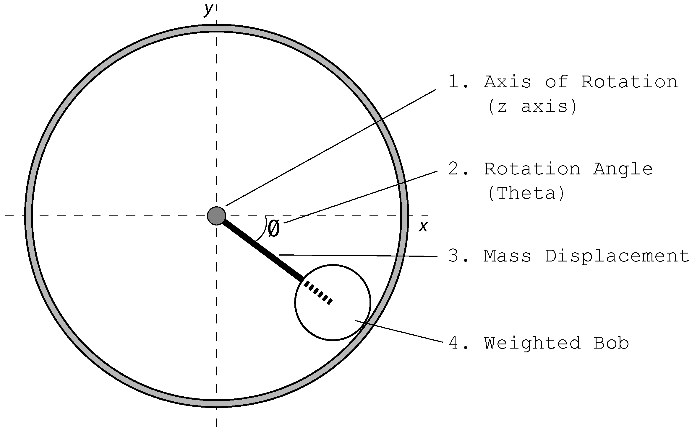
The term barycenter offset is used in spherical robots to describe the act of shifting a robot’s center of mass (the barycenter) in order to produce a desired motion. Consider a robotic sphere resting in equilibrium. As its internal mechanisms move, the mass distribution of the ball will be shifted, causing the ball to roll to a new position of equilibrium. With proper timing and control methodologies, the robot can move smoothly through its environment. However, the main limitation of this method is that the maximum output torque is constrained because the center of gravity cannot be shifted outside of the shell. This can best be illustrated by picturing a pendulum inside a sphere, which is a common and straightforward design. A simplified two-dimensional model (See Figure 1) illustrates the torque that can be generated and mechanically applied to the outer shell. A weighted bob of a given mass swings on an armature about a support rod located through the center axis of the robot. As the bob rotates, the center of mass rotates accordingly and the robot rolls to equilibrium.
Figure 1.
Cross section of a spherical robot model illustrating the pendulum drive armature and weighted bob.
Figure 1.
Cross section of a spherical robot model illustrating the pendulum drive armature and weighted bob.

The maximum value of the torque that can be applied is
![Robotics 01 00003 i007]() where τ is the output torque about the z-axis (Figure 1, item 1), mg is the weight of the bob (Figure 1, item 4), r is the displacement of the bob’s center of mass from the shell’s center of mass (Figure 1, item 3), and sin(θ) corresponds to the rotation angle from the horizontal (Figure 1, item 2). What follows are variations of the barycenter offset designs.
where τ is the output torque about the z-axis (Figure 1, item 1), mg is the weight of the bob (Figure 1, item 4), r is the displacement of the bob’s center of mass from the shell’s center of mass (Figure 1, item 3), and sin(θ) corresponds to the rotation angle from the horizontal (Figure 1, item 2). What follows are variations of the barycenter offset designs.

2.2. Implementations of Governing Principle
2.2.1. Hamster Ball
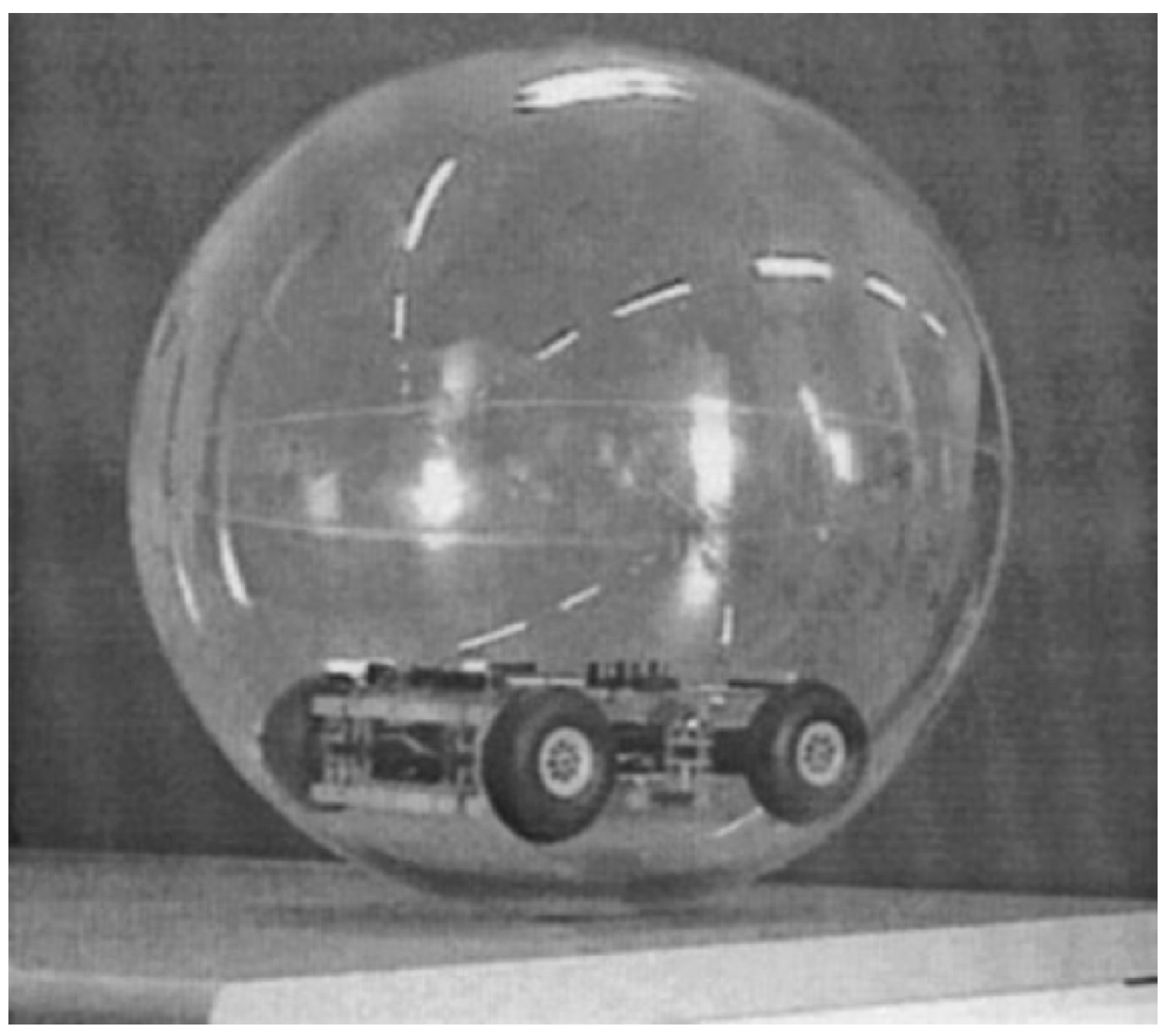
An early design of a barycenter offset system is what is commonly referred to as the hamster ball design [10]. The design is nicknamed this because, simply enough, it mimics a hamster in a toy ball. A small-wheeled robot is placed inside the ball, in most cases a small remote control car, and the weight of the robot provides enough force to propel the robot when it moves (Figure 2). The shell is navigated non-holonomically similar to a car. The heading of the internal robot must be changed in order to change the direction of travel. Single-wheeled or multi-wheeled vehicles can be utilized, and a four-wheeled differential-drive vehicle will create different motion curves as opposed to a single wheeled vehicle [10]. A four-wheel drive system can act as a differential drive, giving the robot the ability to turn in place, which adds holonomic characteristics to the vehicle. Furthermore, the design is relatively easy to model, fabricate, and control. As long as the end task does not require extremely accurate tracking, control is fairly simple as well being that it maneuvers as any type of basic remote control car would maneuver.
Figure 2.
Prototype of a Hamster Ball design [10].
Figure 2.
Prototype of a Hamster Ball design [10].

One of the major drawbacks is that some slipping of the internal robot or driving mechanism usually occurs. However, a closed loop control system combined with appropriate internal tracking sensors can calculate this slippage and may mitigate the problem [10]. Aside from the energy loss and control complications due to friction, another pitfall of this design is the behavior of the robot when it becomes airborne during vibration or encountering bumps. When the internal vehicle becomes airborne, traction between the shell and the internal robot’s wheels becomes zero, and the shell will lose momentum. Furthermore, positional tracking may be affected. Although this problem can be somewhat managed with sensors and a proper control system, in tasks where accuracy of navigation is crucial, this shifting issue is unacceptable.
2.2.2. Internal Drive Unit (IDU)
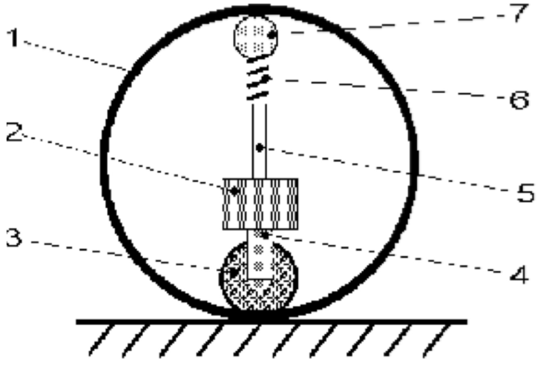
To circumvent the shifting issue associated with an internal robot, a few barycenter offset designs have incorporated a system that forces the robot’s wheels to be in constant contact with the outer shell, either by a spring-loaded or fixed mechanism. In a spring-loaded design, a rod and spring are attached to the top of the internal robot and then pressed up against the shell, forcing the wheels to be in constant contact with the shell. Attached on the top of the spring is a 3-degree-of-freedom (DOF) ball bearing that allows the spring to travel along the surface of the inner shell with little friction (Figure 3).
One of the benefits of having a constant contact between the wheelbase and shell is that the mean speed of the ball can be easily controlled by the motor wheel speed, and at low speeds, the directional control of the system is moderately accurate [1]. The nature of the IDU also allows the system to have either a sealed or a honeycomb outer shell. As long as the wheels are larger than the holes in the outer shell, the robot will continue to operate. Furthermore, this is a simple system to design and is relatively inexpensive to manufacture. It is an excellent research platform that can be used in academia but has challenges operating in real-world situations.
Figure 3.
Structure of Spring-Loaded Design. 1. robot body (case), 2. controlling box, 3. driving wheel, 4. steering axis, 5. supporting axis, 6. spring, 7. balance wheel [1].
Figure 3.
Structure of Spring-Loaded Design. 1. robot body (case), 2. controlling box, 3. driving wheel, 4. steering axis, 5. supporting axis, 6. spring, 7. balance wheel [1].

Although this is still a commonly used low-cost design, at high speeds an IDU-based robot’s heading is difficult to control [1]. Slipping between the wheels and the shell can occur, as well as slipping between the shell and the medium it is traveling on. Slippage issues between the wheel and the shell can be minimized by adjusting the tension between the spring-loaded system and the internal robot, but a tighter fit means higher friction forces throughout the robot. Furthermore, an IDU system cannot make use of stored momentum: if the wheels stop, the robot will behave erratically. An IDU system traveling down a small incline must use power to keep its wheels spinning in order to move: it cannot roll down small inclines without assistance. On the other hand, rolling down steep inclines without controlled power from the internal mechanisms will cause unpredictable movement. From a design perspective, the IDU system must also be extremely well balanced. An off-axis center of mass may cause the robot to travel in an unwanted pattern.
2.2.3. Universal Wheel
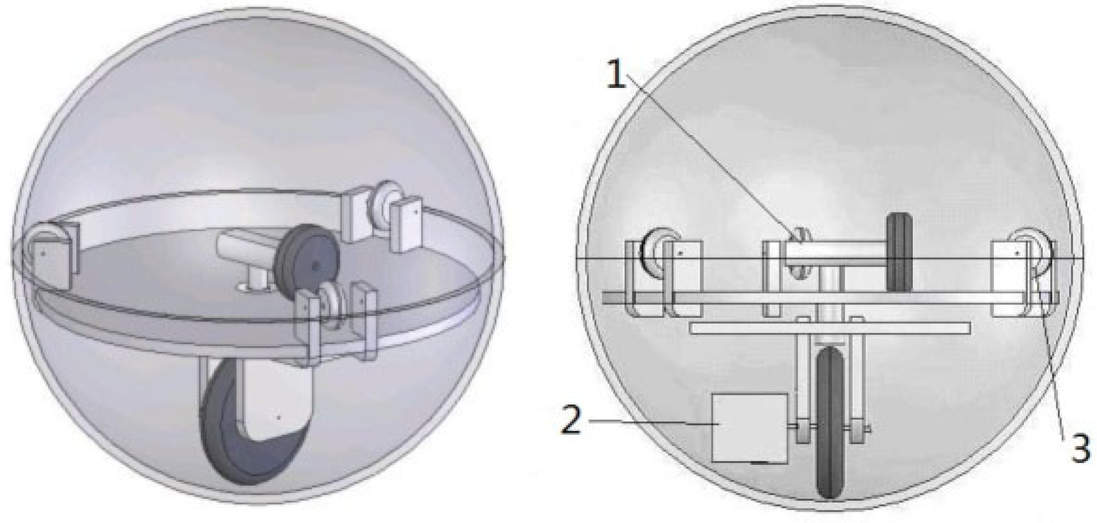
Another design that incorporates the principles of barycenter offset is BHQ-3 [11]. The BHQ series of robots derive their name from the fact that their dynamic model was established from the Boltzmann-Hamel equation. This design is a combination of the hamster wheel and the previous IDU design. It can be conceptualized as a universal wheel type system: the interior drive mechanism can rotate freely on the inside of the robot due to the combination of wheels attached to it. The IDU in the BHQ-3 is designed such that the internal mechanics will not shift when encountering bumpy terrains (Figure 4). Two DC drive motors control the robot: one motor controls the orientation of the IDU, and one motor controls the speed of the drive wheel. This allows the ball to move with a zero turning radius, creating a higher degree of holonomy than the previously described robots. In addition to having the ability to maneuver itself by the use of barycenter offset, the robot’s velocity is also controlled by the angular velocity of the driving wheel. As the wheel spins faster, the translational velocity of the robot increases. This means that the internal weight of the IDU is not the only factor controlling the momentum of the robot. This particular robot is able to travel in water, sand, as well as up a small slope. However, it may have high energy loss due to friction from the sponge wheels as well as the inability to roll unpowered down a slope, depending on the motors and control method used.
Figure 4.
Structure of BHQ-_3: 1–Motor, 2–Motor, 3–Sponge wheels [11].
Figure 4.
Structure of BHQ-_3: 1–Motor, 2–Motor, 3–Sponge wheels [11].

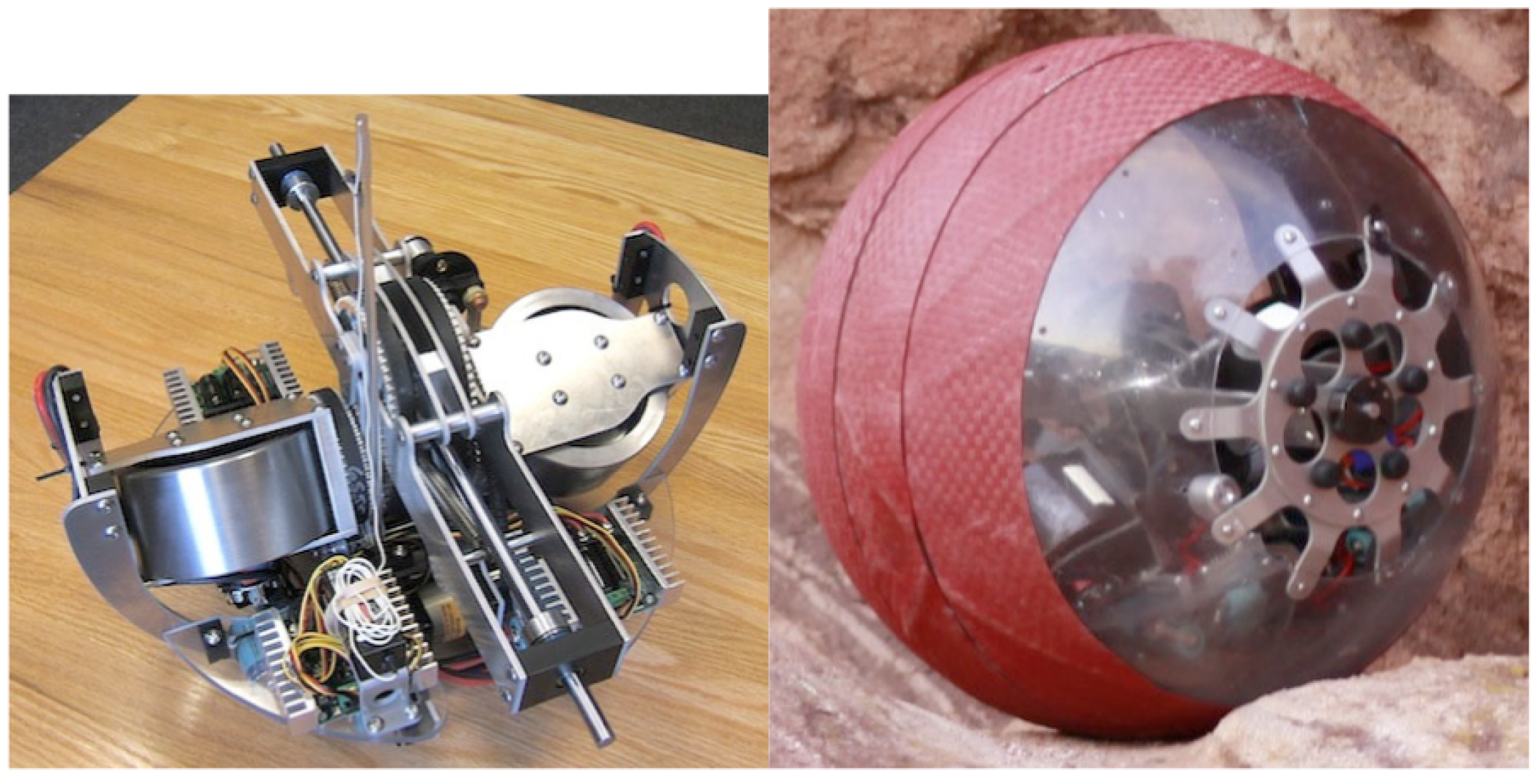
The HIT Spherical Robot [12] was designed to behave in a manner where the steering and driving mechanisms are independent of one another (Figure 5). In a pendulum-based designed, the steering and turning mechanisms are dependent on each other, creating a non-holonomic robot. For a robot to be able to move in any direction regardless of orientation (holonomy), the steering and driving mechanisms must be mechanically independent. HIT is only controlled by two motors: a turning and a driving motor. The turning motor (Item 1, Figure 4) rotates the entire inner assembly of the robot along a rim at the equator, and the driving motor (Item 2, Figure 4) shifts the center of gravity of the robot, causing it to move.
Figure 5.
A picture of HIT and its internal driving mechanism [12].
Figure 5.
A picture of HIT and its internal driving mechanism [12].

2.2.4. Pendulum Driven
A popular design used by industry and academia is a pendulum-driven design (Figure 6). The pendulum model consists of a fixed shaft through the center of the outer shell of the robot, with a pendulum and bob that rotates around the shaft. Rotating the pendulum shifts the center of mass outward from the center and the shell begins to roll. Shifting the pendulum left or right along the equator will shift the center of mass left or right, and the robot will begin to turn in the corresponding direction. Shown in Figure 6 below is a photo of a commercialized pendulum robot, Rotundus.
Figure 6.
A commercialized pendulum-driven robot, Rotundus [13].
Figure 6.
A commercialized pendulum-driven robot, Rotundus [13].

As the weight of the bob increases, so does the amount of torque that can be used to drive the robot. However, a heavier bob means a heavier robot. The most notable setback to this design is its inability to go up a steep slope. If the bob is where the majority of the weight of the system is located, the robot can go up a steep slope. However, in practice, a well designed spherical robot can usually only go up about a 30° slope [14]. A spherical robot that can traverse an incline greater than 30° may require design techniques that are not commercially or economically practical. Even though there are some limitations to the pendulum drive, it is a low-power easy-to-implement design that allows the shell to be sealed. Rotundus can roll at speeds of 6mph, through snow, ice, mud, and sand, and can float. In addition, it can carry a 1.81 kg payload [13].
One drawback to this design is that the movement of the shell is non-holonomic: there is a turning radius associated with its movement. Like all other barycenter offset designs, the center of mass cannot be shifted outside of the boundaries of the shell. It is also important to consider that as the radius of the shell becomes larger and the pendulum bob becomes more massive, the output torque increases. However, as these items become larger, the energy required to move them also becomes larger. There is a delicate balance of design when considering material compositions and the physical sizes of the internal elements.
Figure 7.
Rear view of Roball’s steering mechanism [15].
Figure 7.
Rear view of Roball’s steering mechanism [15].

Designed to be a child’s toy, Roball [15] is a pendulum-based spherical robot with an added tilt mechanism allowing it to turn as shown in Figure 7. The robot was designed to operate in unconstrained environments and have minimal cost and complexity. Onboard sensors allow the robot to navigate its environment autonomously. All elements are placed on a plateau of the robot (the equator), and steering is done using a counterweight. In this particular model, the counterweight is a battery. In this design, the counter weight is designed to stay at the bottom of the shell, and the shell moves around it, causing propulsion. In previous examples, the internal masses are designed to move within the shell and the robot rolls to equilibrium.
2.2.5. Double Pendulum
Another novel concept proposed in recent literature is a drive system with two pendulums on the inside. B. Zhao proposes such a device with an elliptical shell. Paired with a double pendulum, this allows the robot to turn in place [16,17]. Parameters such as speed and maximum incline are not optimized in this design because the research is focused mainly on proof of concept and path planning. Springs are added to the system to dampen impacts on the internal mechanisms when traversing rough terrain or large bumps. The literature presents the theory, which is verified by simulation, and is then demonstrated on a proof-of-concept physical prototype (Figure 8).
Figure 8.
Mechanical structure of dual pendulum robot designed by Zhao: (1) Motor A; (2) Motor B; (3) Ballast B; (4) Ballast A; (5) Spring; (6) Linear Bearing; (7) Guide; (8) Outer Shell [16,17].

The robot is able to turn in place by usage of the “Stick-Slip” principle. In the first stage (stick), each pendulum is rotated up to a horizontal position slowly, but in opposite directions. This will cause a shift in the equilibrium and the robot will want to turn, but because the pendulums are rotated up slowly, the shift in equilibrium is not large enough to overcome the static friction force holding the robot in place. In the next stage (slip), the pendulums are quickly forced down to their original vertical orientation. This also causes a shift in equilibrium, but the rapid movement is enough to overcome the static friction force causing the robot to slip and turn in place.
Another type of dual pendulum design is seen in Kisbot II. Its predecessor, Kisbot I, was based on a single pendulum design and had adaptive legs allowing it to climb stairs (discussed below). Kisbot II overcomes the need for utilization of the stick-slip principle by allowing the internal mechanics to rotate about an axis perpendicular to the axis of pendulum movement [18]. The axes of rotation of Kisbot II are pictured below.
Figure 9.
Axes of rotation of pendulums for Kisbot II. (a) Side view (b) Front view [18].
Figure 9.
Axes of rotation of pendulums for Kisbot II. (a) Side view (b) Front view [18].

The side view of Kisbot II is shown in Figure 9(a), and the front view is shown in Figure 9(b). The side view illustrates the ability of the pendulums to rotate independently of each other in either direction about the diameter of the robot. Theoretically, the stick-slip principle described by B. Zhao could also be used to turn the robot in place. However, by adding the extra degree of freedom shown in Figure 9(b), the pendulums can rotate Kisbot II from left to right as well as from front to back, eliminating the need for the stick-slip principle.
Figure 10.
Picture of Spherobot and its system of shifting masses [19].
Figure 10.
Picture of Spherobot and its system of shifting masses [19].

Some teams have devised another method altogether for barycenter offset designs. By placing the bulk of materials in the center of robot, the energy required to spin the sphere is reduced. Shafts connect the center mass to the outer shell and weights are designed to traverse these shafts as shown in Figure 10. By moving the weights up and down the shaft, the center of mass is changed and the ball begins to roll [19]. A few main differences separate this shifting mass design from the pendulum design. First, this design is holonomic. Regardless of its orientation, it can move in any direction. However, the controls are more complicated because the main processor must keep real time orientation data as well as distance data of all masses. Another downside to this design is that the internal weights traverse their respective shafts slowly, resulting in a slow moving robot. It also may have a hard time rolling downhill freely depending on state of the masses.
2.2.6. Notable Enhancements
Novel add-ons to spherical robots are as diverse as the methods used to drive them. Designs incorporate sensors, telescopic cameras, reconfigurable legs, and even jumping mechanisms. Some designs even have the ability to transform completely.
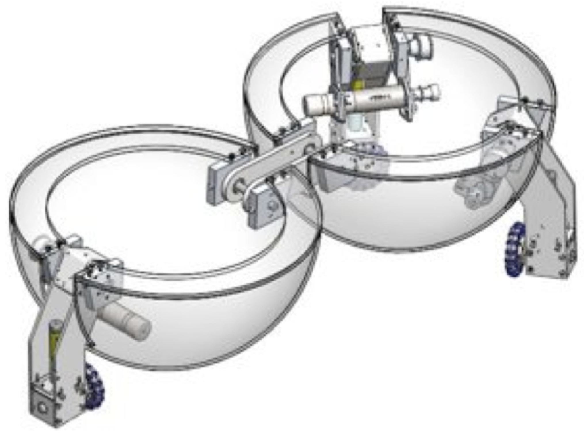
N. Chadill presents a reconfigurable robot that can transform from a sphere into a dual hemisphere platform with three legs and omnidirentional wheels [20] (Figure 11). The ideology behind the vehicle is that it can compact itself into a sphere for transportation and deployment but will function as a leg-wheeled robot after reconfiguration. The once spherical robot can then navigate pathways autonomously as any other wheeled vehicle can. Currently, the design does not actively roll when in its spherical configuration, but this idea can be applied to current spherical robot designs.
Figure 11.
Image of spherical robot after reconfiguration [21].
Figure 11.
Image of spherical robot after reconfiguration [21].

Another reconfigurable spherical robot with deployable legs is Kisbot I, the predecessor to Kisbot II, which is mentioned in Section 2.2.5. Kisbot I has two types of drive modes: a pendulum-driven mode and wheel-driven mode [22]. While the legs are retracted to the interior of the robot, the robot can maneuver as a pendulum model. In its wheeled mode, the legs extend, stabilizing the robot, and it can be driven like a wheeled vehicle. The legs can also be deployed for stopping and climbing, seen in Figure 12. Each leg resides in an independent hemisphere that can rotate independently of the other semi-sphere. Because the hemispheres are independent, the legs may not necessarily need to be deployed on the same Cartesian plane. This allows for the possibility of the robot to stabilize itself in unusual terrains.
Another way to allow a spherical robot to climb large obstacles would be to give it the ability to jump. In a paper presented by L. Bing, a spherical robot driven by dual pendulums is retrofitted with a mechanism that gives it the ability to jump [23]. The jumping mechanism on the robot allows it to jump at a desired angle and direction once it has reconfigured itself to do so as shown in Figure 13. This is an extremely useful characteristic for robots of this nature because of their inability to climb steep slopes. In order to jump, the robot stores energy in a spring by extending it with a large mass attached to it. When the spring is released, the mass is accelerated upwards and collides with the top of the robot. Due to the laws of conservation of momentum, the entire robot continues upwards with the mass.
Figure 12.
Movement types of Kisbot I [22].
Figure 12.
Movement types of Kisbot I [22].

Figure 13.
Image of hopping robot and its jumping mechanism [23].
Figure 13.
Image of hopping robot and its jumping mechanism [23].

3. Shell Transformation
3.1. Governing Principle
Although not as common as barycenter offset designs, shell transformation is also a novel method of propelling a spherical robot. This idea is fairly new and has some interesting concepts associated with it. Instead of a complicated internal mechatronics system to propel the sphere, the robot relies on transformation of its outer body. This can be achieved by deformation of the encompassing shell, or having environmental elements, such as wind or water, act on the body itself. Depending on the design, this family of robots may prove to be more versatile than a barycenter offset type of system. However, this concept is still in its infancy compared with the designs discussed above and it has potential for future research. Hence, the ideas are novel and deserve further investigations.
3.2. Implementations of Governing Principle
3.2.1. Pressurized Air Bladders
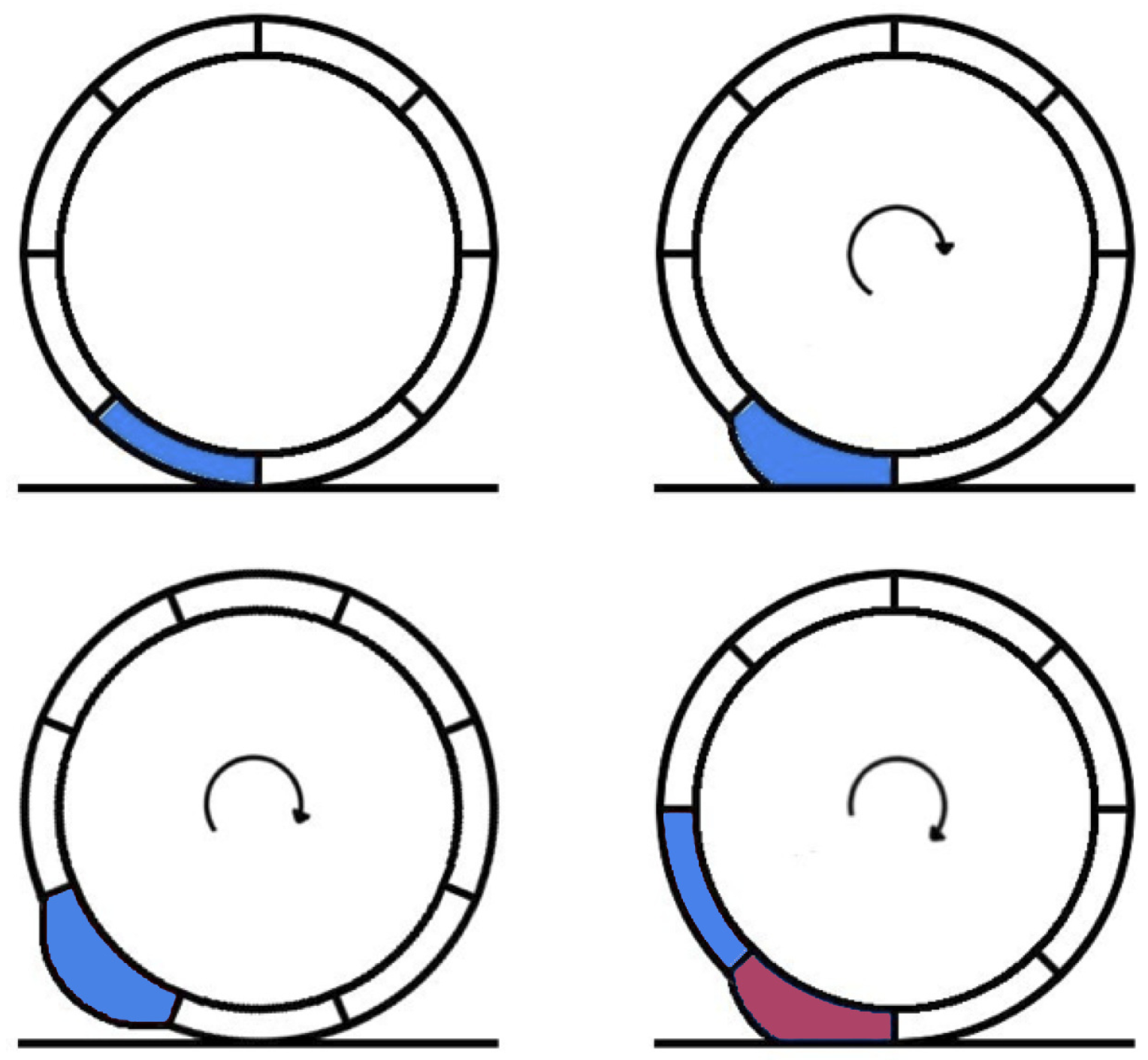
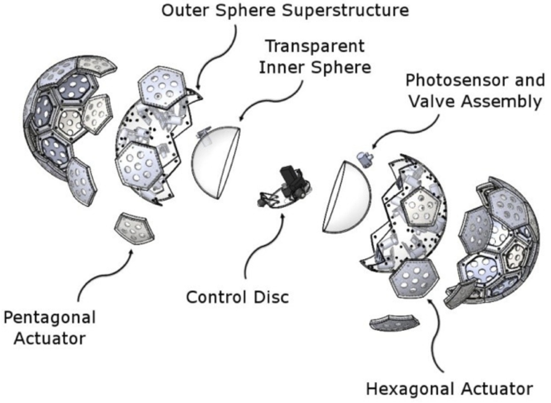
A basic deformable spherical rover is proposed by M. Artusi [24]. The outer shell consists of four dielectric elastomer actuators sections, which can be transformed by applying an electric field. Transformation of the sections in sequence will cause the robot to roll. K. Wait proposes a similar, yet more advanced idea that utilizes pressurized air bladders. The robot is extremely similar to a soccer ball where each pentagonal section of the outer sphere can inflate and deflate [25]. Each section of the outer sphere is actually an elastomer bladder that can be filled with air. Depending on which sections are filled with air, the sphere can be pushed along a path as shown in Figure 14. Ingeniously, this type of system can provide holonomic movements. Multiple bladders can be inflated allowing for a various directions of travel.
Figure 14.
Soccer ball type robot movement [25].
Figure 14.
Soccer ball type robot movement [25].

Figure 15.
Breakaway view of the soccer ball robot [25].
Figure 15.
Breakaway view of the soccer ball robot [25].

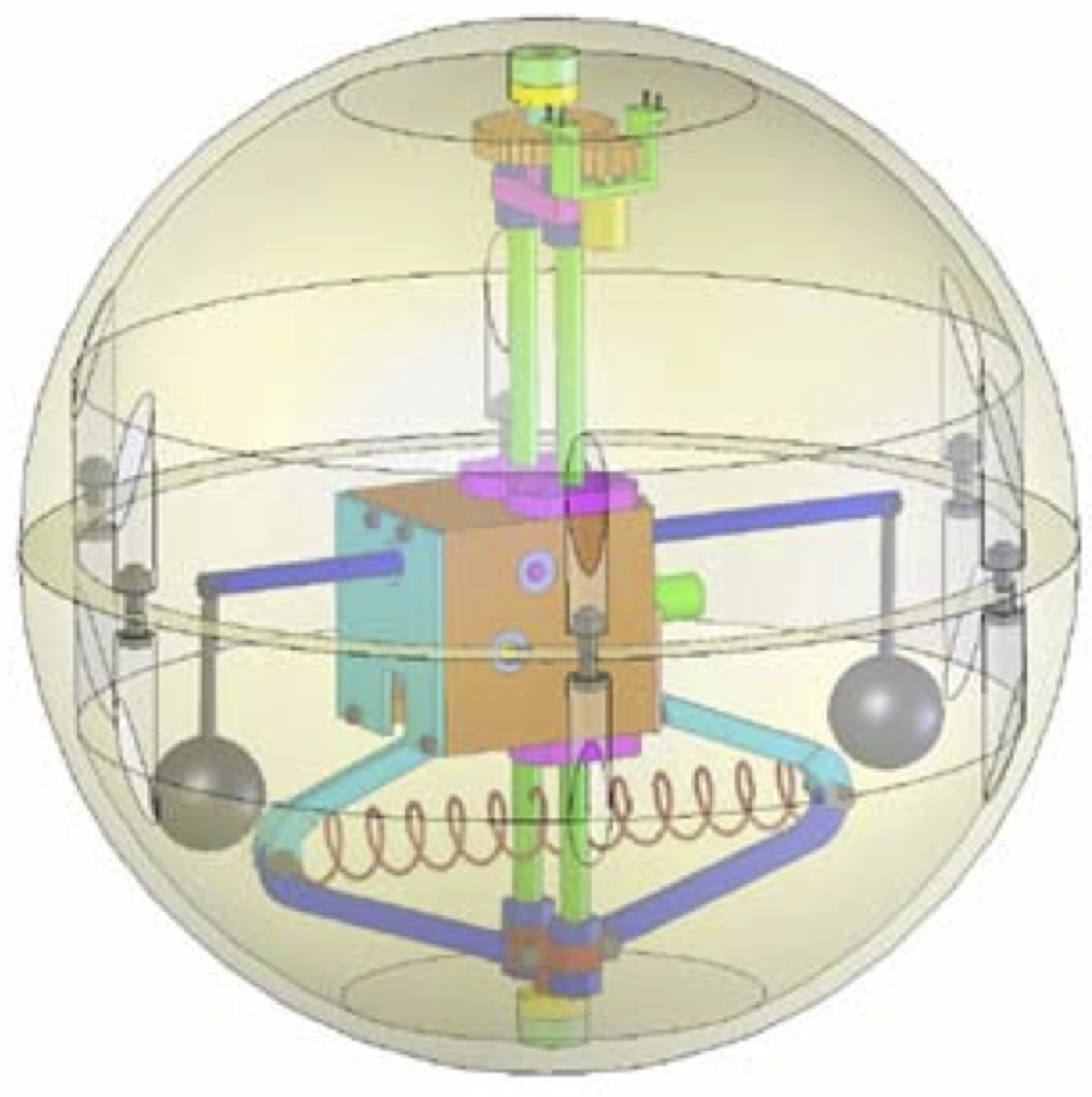
A notable outcome resulting from this research is the design of the control method, which is for the most part non-computational when compared with the previously discussed designs. Inside of the soccer ball shell there is another spherical robot altogether, designed extremely similar to the hamster ball and IDU design discussed in Section 2. On the rear of the control disc, which is inside the inner shell (shown in Figure 15, there is a high power LED. Each of the pentagonal bladders is equipped with a photo diode. As the control disc moves via radio control, the LED shines on the photo diodes of the bladders, inflating the proper bladders and thus moving the robot.
3.2.2. Shape Memory Alloys
Others have even proposed deforming the outer shell in such a way that will allow the robot to jump. T. Yamanaka proposes such a robot with “Super-ball-like" properties [26]. Superballs have a unique way of bouncing due to their spin and elastic properties. By manipulating the outer shell and placing a rotor in the internal structure, the robot should be able to have controlled hops. Sugiyama proposes and demonstrates locomotion entirely by manipulation of the outer shell [27]. The robot is comprised of shape memory alloy (SMA) coils that can be extended/retracted when voltage is applied to them. This allows the robot to flatten like a pancake and spring back to its original form in an instant, causing it to jump. When controlled properly, it can also be used for smooth locomotion as shown in Figure 16.
Figure 16.
Locomotion by deformation of SMA coils [27].
Figure 16.
Locomotion by deformation of SMA coils [27].

4. Conservations of Angular Momentum (COAM)
4.1. Governing Principle
Barycenter offset designs are by far the most widely used design due to their lack of complication and ease of control, with shell transformation the next most frequent design. Although barycenter offset designs are commonly implemented, a major limitation is that because the center of mass can never go outside of the sphere, it becomes a torque-limited system.
In the last 20 years, the concept of adding control moment gyroscopes (CMGs) to a spherical robot has started to be investigated by various research groups. By spinning a large flywheel rapidly and rotating it about an axis, the laws of conservation of angular momentum can be used to control the movement of the sphere. Using this method relates the output torque of the internal mechanism to the angular velocity of the CMGs. As the angular velocity of the CMGs increase, so does the output torque. This is the most recent method in obtaining an output torque greater than that can be produced by a barycenter offset type system. To date, there have been multiple designs incorporating flywheels, each with varying successes and failures.
A unique feature of using a CMG is that these systems have reaction forces in all three spatial dimensions. If a CMG is spinning about the X-axis, and is rotated about the Y-axis, then there will be a torque about the Z-axis (precession). This feature has an obvious useful potential (generating a torque in the intended direction) but also causes control issues. Depending on the design of the robot, the precession torque can be utilized to control or augment the robot’s angular momentum. However, if the design does not take this extra dimension of torque into account, it may steer the robot in an unwanted direction. Therefore, although a gyro-based or gyro-augmented spherical robot may be able to outpower—in terms of torque—a barycenter offset robot, there are other design challenges that must be faced before that can occur.
4.2. Implementations of Governing Principle
4.2.1. Balancing
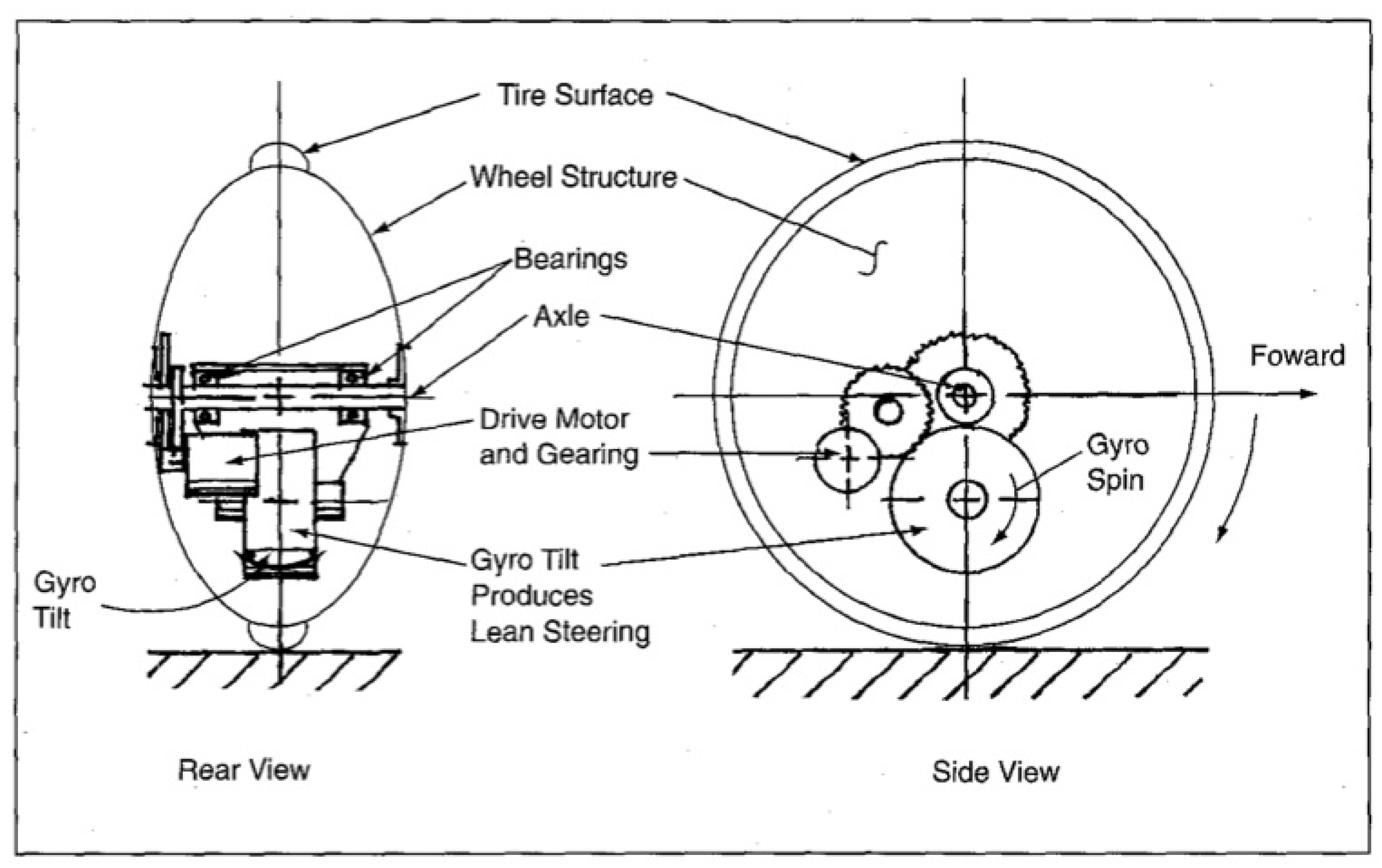
An early approach was Gyrover, a disc-like object that balanced on its edge [28,29]. An internal gyroscope was used to balance the robot, and the effects from the precession torque were used to steer it. Although novel in its design, it may be impractical for commercial usage. The literature states that it can be used at high speeds and on rough terrain. It can also turn in place, which can provide some degrees of holonomy. On the other hand, the robot may have difficulty correcting its orientation if it were to fall on its side. Furthermore, it may be difficult to make precision movements of the robot unless the embedded electronics and mechanics are extremely well designed.

4.2.2. Uni-Dimensional COAM
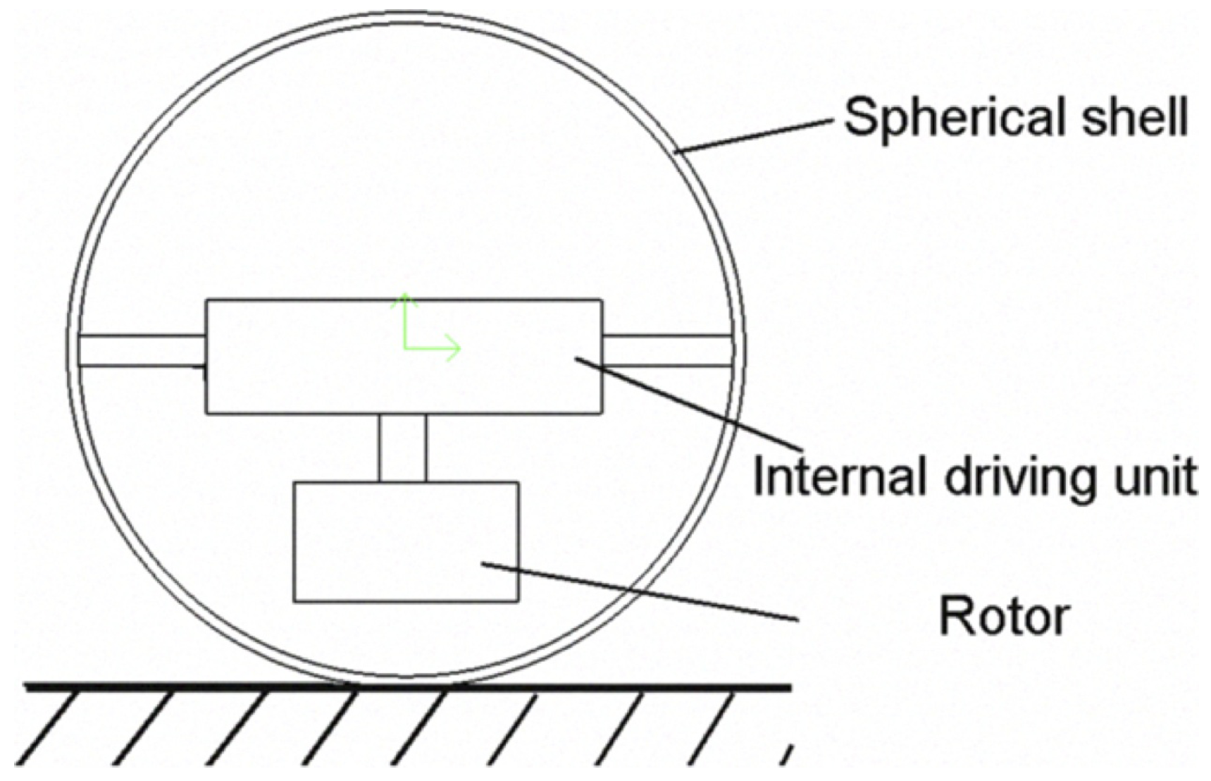
A UNI-Dimensional COAM design of this type is presented by Shu [30]. In this design, a variable speed rotor is used for a bob. However, this particular design utilizes the CMG bob in a different manner than a standard pendulum-type drive system does. The acceleration from spinning the CMG faster or slower will cause the shell to turn. Furthermore, if the CMG is already spinning at a high rate, maneuvering it up and down as if it were a bob will cause a precession torque that may achieve higher torques than a normal pendulum-based design (see Figure 18). This robot utilizes COAM in a one-dimensional manner, but has the ability to reorientate that dimension in order to control its movement.
Figure 18.
Schematic of rotor-based bob presented by S. Guanghui [30].
Figure 18.
Schematic of rotor-based bob presented by S. Guanghui [30].

V. Joshi presents a robot that is controlled by two pairs of diametrically opposed CMGs as shown in Figure 19 [31,32]. A single motor controller controls each CMG pair. As a pair’s angular velocity increases, the shell will rotate in the opposite direction in order to maintain the system’s total angular momentum. Having a second pair inside the ball means the ball’s movement has a second degree of freedom and can move in a true holonomic manner. The state space calculations for this type of robot are much more complicated than a simple barycenter offset design, but true holonomy can be achieved. This is categorized as a Uni-Directional COAM robot because it has two systems that utilize the laws of COAM, but each system only involves one spatial plane in its COAM dynamics.

4.2.3. Tri-Dimensional COAM
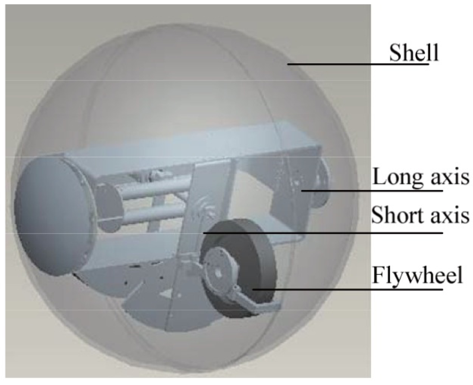
The fifth robot in the BHQ series, BHQ-5, uses a pendulum type of drive system with a control moment gyroscope to augment the stability of the robot as shown in Figure 20 [33]. With the CMG placed where the bob of the normal pendulum system would be, the robot is able to rotate itself depending on how the CMG rotates. Furthermore, depending on the orientation of the CMG and how it is moved, it can also increase the angular momentum of the robot as well, providing more torque than just a normal pendulum and bob would. Simplifying the idea for explanatory purposes, this can be thought of as a pendulum-type robot with a bob of variable mass. As with a pendulum type robot, the bob on this particular design can either steer or propel the robot, but in this case with varying levels of power. The BHQ-5 utilizes precession torque of a CMG, and it therefore incorporates all three spatial dimensions into its COAM dynamics.
Figure 20.
BHQ-5, a pendulum type robot with a CMG in place of a bob [33].
Figure 20.
BHQ-5, a pendulum type robot with a CMG in place of a bob [33].

4.2.4. Scissored-Pairs
The idea of using gyroscopes for conservation of angular momentum based spatial control has been utilized to control large space structures such as the International Space Station and to stabilize large telescopes [34]. More complex designs can even be used as inertial dampers in space. Based on the mission, four to six variable-speed control moment gyroscopes can be configured in such a system [35]. As mentioned before, use of control moment gyroscopes has an advantage and a disadvantage: an action on the gyroscope causes a reaction in two orthogonal planes of space. This means that unless this is accounted for in the design, it can cause unwanted problems.
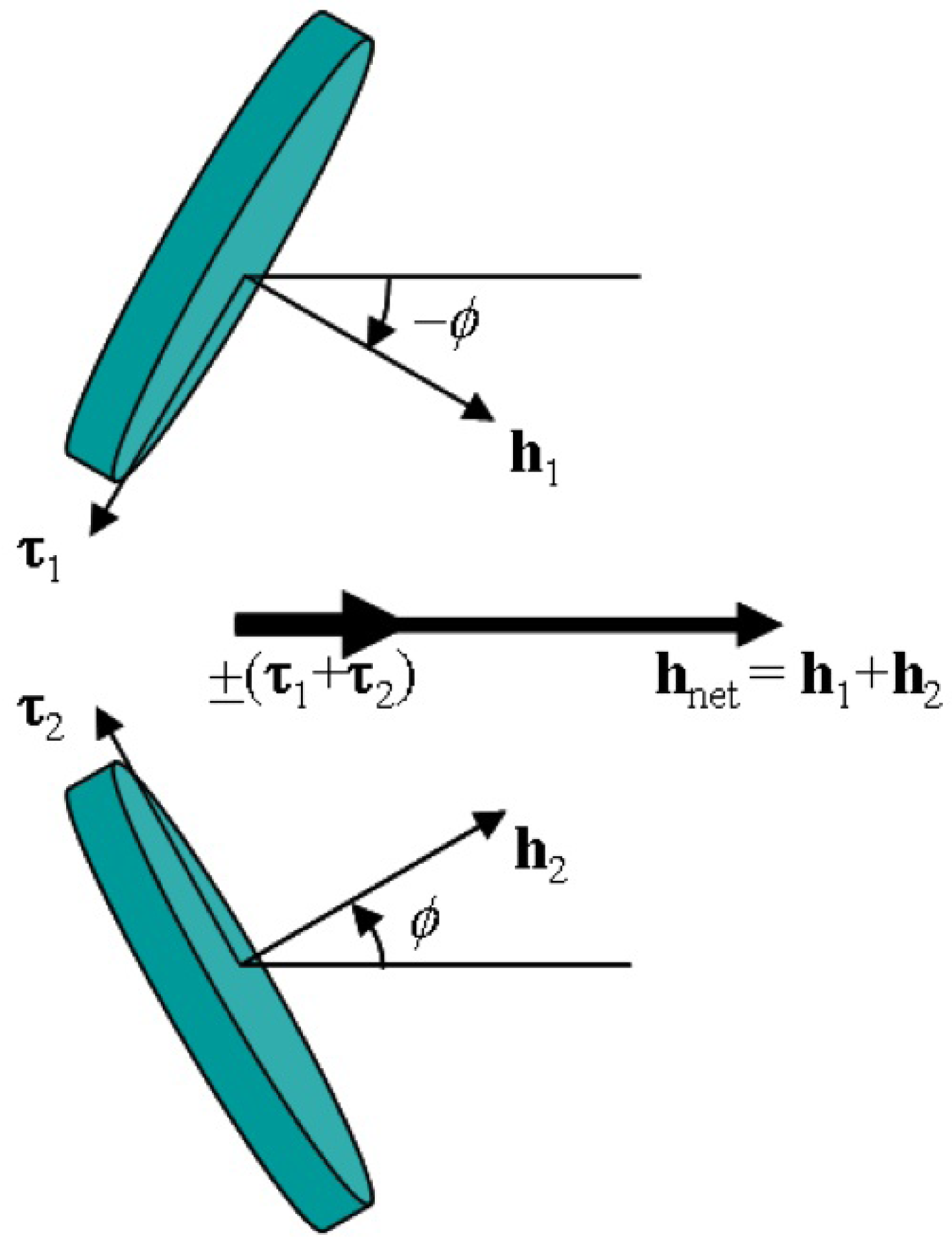
One novel way to circumvent this issue is the use of a scissored-pair (Figure 21). By pairing each control moment gyroscope with another that is spinning in the opposite direction at the same magnitude (h1 and h2), the reaction from the changing spin of the gyroscopes cancel each other out and now an action on gyroscope pair (τ1 and τ2), causes a reaction in only one direction (hnet). However, one downside of this configuration is that hnet switches direction after θ becomes 180° or more. After that, the direction of hnet is pointed in the opposite direction, and goes back to the original direction when θ becomes zero. Spinning the CMGs down to zero angular velocity or spinning the CMGs in the opposite direction can neutralize this phenomenon. This configuration has recently been used in space robotics applications for low power actuators [36], and even more recently been used in augmenting spherical robot control.
Usage of such a device is exhibited in G. Schroll’s Master’s thesis as well as patent [14,37]. The design won him the Collegiate Inventors Competition in 2008, and he was the first undergrad to ever receive the award [38]. The robot can be thought of as an enhanced pendulum-type design. It incorporates a variable-speed scissored pair into its bob, allowing it to have a torque greater than mgr*sin(θ) (shown in Figure 1). The output torque can be thought of as
![Robotics 01 00003 i008]() where hnet is the torque from the scissored pair, m is the mass of the bob, and r is the radius of the bob from the center of the robot. Since hnet is a function of the angular velocity of the CMG pair, the output torque is no longer dependent on the weight of the bob, proverbially allowing the center of mass to be shifted outside of the shell. Videos show the robot climbing out of steep holes and making sharp turns. Although the control system is still being researched, this is a viable solution to the torque limit analogous with pendulum-based designs.
where hnet is the torque from the scissored pair, m is the mass of the bob, and r is the radius of the bob from the center of the robot. Since hnet is a function of the angular velocity of the CMG pair, the output torque is no longer dependent on the weight of the bob, proverbially allowing the center of mass to be shifted outside of the shell. Videos show the robot climbing out of steep holes and making sharp turns. Although the control system is still being researched, this is a viable solution to the torque limit analogous with pendulum-based designs.

Figure 21.
Picture of a Scissored-Pair configuration [39].
Figure 21.
Picture of a Scissored-Pair configuration [39].


Although this is an innovative approach, it is only a momentary boost of torque and does not provide a continuous driving force. As mentioned above, the torque boost only lasts for a rotation of 180°. After that boost, the CMGs must be reconfigured either through mechanical or control methods in order to prevent an unwanted secondary boost in the opposite direction. This presents a whole new area of research for spherical robots, as there are many possibly ways to achieve such an effect: gearing, controlling spin of the gyroscope speed, etc. A proper control method or mechanical design to change the output torque direction of a scissored pair from an oscillating to a uni-directional state may lead to a highly advanced spherical robot design.
5. Summary and Conclusions
Spherical robots have an abundant number of usages with an equal number of methods to control them. A brief table of taxonomy is shown in Table 1. Most of the types of active drive designs are based on three main principles: offset of center of gravity (barycenter offset), outer-shell deformation, or conservation of angular momentum. Compared with the other methods, the designs based on barycenter offset tend to be the least complex and can be controlled relatively easily. Generally speaking, barycenter offset designs can be analyzed with a single model (Figure 3). However, the power in these robots is limited because the center of gravity cannot be moved outside of the shell. Common types of barycenter offset designs include a single wheel model, car model, universal wheel model, and a pendulum model. These are the most commonplace of the designs with a large amount of research data available on them.
Designs utilizing methods of conservation of angular momentum typically involve creating torque by manipulating a single axis or three axes of a CMG. Designs can either utilize the counter rotational force generated when spinning a CMG faster or slower (single-axis), or the precession torque created when rotating an already spinning CMG orthogonal to its axis of spin (triple-axis). The magnitude of torque generated in single axis designs is controlled by the amount of acceleration of the spinning CMG, whereas in triple axis designs, the precession torque is controlled by the angular velocity times the rotational acceleration. CMGs integrated into a spherical robot offer a way to solve the power constraints placed on spherical robots by barycenter-offset designs, but this method has its own unique set of hurdles to overcome. Shell transformation designs are a rather new concept and may be more difficult to design but can be maneuvered with an almost calculation-less control method. Groups have begun merging these three concepts together producing robots that have advantages over designs based on a single concept. Marriages of multiple principles, such as a pendulum type with a CMG bob, have proved to be noteworthy concepts. Future research on gyroscope-augmented designs may lead to technology that can be integrated into a fast, agile, holonomic spherical robot.

Table 1.
Table of Taxonomy: Type Number, Governing Principle, Source of Movement, and Dominant Power Factor.
| Type | Principle | Method | Source of Movement | Power Factor | Example |
|---|---|---|---|---|---|
| 1 | BCO | Shifting COG | COG Shift |  | R. Mukherjee et al. [19] |
| 2 | BCO | Single Wheel | Equilibrium Change |  | Halme et al. [1] |
| 3 | BCO | Universal Wheel | Downward Force on Shell |  | Zhan et al. [11] |
| 4 | BCO | Pendulum | Torque about Diameter |  | Michaud et al. [15] |
| 5 | COAM | Single-Axis | Reaction force from spin of CMG |  | Guanghui et al. [30] |
| 6 | COAM | Triple-Axis | Precession Torque |  | Schroll et al. [14,37] |
| 7 | OST | Shell Transformation | Various | Various | Artusi, Wait, Yamanaka, Sugiyama et al. [24,25,26,27] |
References
- Halme, A.; Schonberg, T.; Wang, Y. Motion Control of a Spherical Mobile Robot. In Proceedings of the 4th International Workshop on Advanced Motion Control (AMC’96-MIE), Tsu-City, Japan, March 1996; 1, pp. 259–264.
- Lin, X.; Guo, S.; Tanaka, K.; Hata, S. Development of a Spherical Underwater Robot. In Proceedings of 2011 IEEE/ICME International Conference on Complex Medical Engineering (CME), Harbin, China, May 2011; pp. 662–665.
- Lin, X.; Guo, S.; Tanaka, K.; Hata, S. Underwater Experiments of a Water-Jet-Based Spherical Underwater. Robot. In Proceedings of 2011 IEEE International Conference on Mechatronics and Automation (ICMA), Beijing, China, August 2011; pp. 738–742.
- Michaud, F.; Laplante, J.; Larouche, H.; Duquette, A.; Caron, S.; Létourneau, D.; Masson, P. Autonomous spherical mobile robot for child-development studies. IEEE Trans. Syst. Man Cybern. A 2005, 35, 471–480. [Google Scholar] [CrossRef]
- Kenyon, S.; Creary, D.; Thi, D.; Maynard, J. A small, cheap, and portable reconnaissance robot. Proc. SPIE 2005, 5778, 434–443. [Google Scholar]
- Seeman, M.; Broxvall, M.; Saffiotti, A.; Wide, P. An Autonomous Spherical Robot for Security Tasks. In Proceedings of 2006 IEEE International Conference on Computational Intelligence for Homeland Security and Personal Safety, Orlando, FL, USA, April 2006; pp. 51–55.
- Yili, Z.; Hanxu, S.; Qingxuan, J.; Chenkun, S.; Kailiang, Z. An Omni-Directional Rolling Spherical Robot with Telescopic Manipulator. In Proceedings of the 2nd International Symposium on Systems and Control in Aerospace and Astronautics (ISSCAA 2008), Shenzhen, China, December 2008; pp. 1–6.
- Appelqvist, P. Mechatronics Design of a Robot Society: A Case Study of Minimalist Underwater Robots for Distributed Perception and Task Execution; Helsinki University of Technology: Helsinki, Finland, 2000. [Google Scholar]
- Liu, D.; Sun, H.; Jia, Q. A Family of Spherical Mobile Robot: Driving Ahead Motion Control by Feedback Linearization. In Proceedings of the 2nd International Symposium on Systems and Control in Aerospace and Astronautics (ISSCAA 2008), Shenzhen, China, December 2008; pp. 1–6.
- Alves, J.; Dias, J. Design and control of a spherical mobile robot. Proc IME J. Syst. Contr. Eng. 2003, 217, 457–467. [Google Scholar]
- Zhan, Q.; Cai, Y.; Yan, C. Design, Analysis and Experiments of an Omni-Directional Spherical Robot. In Proceedings of 2011 IEEE International Conference on Robotics and Automation (ICRA), Shanghai, China, May 2011; pp. 4921–4926.
- Yue, M.; Deng, Z.; Yu, X.; Yu, W. Introducing HIT Spherical Robot: Dynamic Modeling and Analysis Based on Decoupled Subsystem. In Proceedings of IEEE International Conference on Robotics and Biomimetics (ROBIO’06), Kunming, China, December 2006; pp. 181–186.
- Rotundus. Available online: http://www.rotundus.se (accessed on 22 May 2012).
- Schroll, G. Dynamic Model of a Spherical Robot from First Pinciples. M.S. Thesis, Colorado State University, Fort Collins, CO, USA, 2010. [Google Scholar]
- Michaud, F.; Caron, S. Roball, the rolling robot. Auton. Robots 2002, 12, 211–222. [Google Scholar] [CrossRef]
- Zhao, B.; Wang, P.; Hu, H.; Li, M.; Sun, L. Study on Turning in Place of a Spherical Robot Based on Stick-Slip Principle. In Proceedings of 2009 IEEE International Conference on Robotics and Biomimetics (ROBIO), Guilin, China, December 2009; pp. 771–775.
- Zhao, B.; Li, M.; Yu, H.; Hu, H.; Sun, L. Dynamics and Motion Control of a Two Pendulums Driven Spherical Robot. In Proceedings of 2010 IEEE/RSJ International Conference on Intelligent Robots and Systems (IROS), Taipei, Taiwan, October 2010; pp. 147–153.
- Yoon, J.; Ahn, S.; Lee, Y. Spherical Robot with New Type of Two-Pendulum Driving Mechanism. In Proceedings of 2011 15th IEEE International Conference on Intelligent Engineering Systems (INES), Poprad, Slovakia, June 2011; pp. 275–279.
- Mukherjee, R.; Minor, M.; Pukrushpan, J. Simple Motion Planning Strategies for Spherobot: A Spherical Mobile Robot. In Proceedings of the 38th IEEE Conference on Decision and Control, Phoenix, AZ, USA, December 1999; 3, pp. 2132–2137.
- Chadil, N.; Phadoongsidhi, M.; Suwannasit, K.; Manoonpong, P.; Laksanacharoen, P. A Reconfigurable Spherical Robot. In Proceedings of 2011 IEEE International Conference on Robotics and Automation (ICRA), Shanghai, China, May 2011; pp. 2380–2385.
- Jearanaisilawong, P.; Laksanacharoen, S.; Piriyawong, V.; Swatdipisal, K. Design of a Three-Legged Reconfigurable Spherical Shape Robot. In Proceedings of IEEE/ASME International Conference on Advanced Intelligent Mechatronics, Singapore, July 2009; pp. 1730–1733.
- Kim, Y.; Ahn, S.; Lee, Y. KisBot: New Spherical Robot with Arms. In Proceedings of the 10th WSEAS International Conference on Robotics Control and Manufacturing Technology, Hangzhou, China, April 2010; pp. 63–67.
- Li, B.; Deng, Q.; Liu, Z. A Spherical Hopping Robot for Exploration in Complex Environments. In Proceedings of 2009 IEEE International Conference on Robotics and Biomimetics (ROBIO), Guilin, China, December 2009; pp. 402–407.
- Artusi, M.; Potz, M.; Aristizabal, J.; Menon, C.; Cocuzza, S.; Debei, S. Electroactive elastomeric actuators for the implementation of a deformable spherical rover. IEEE/ASME Trans. Mechatron. 2011, 16, 50–57. [Google Scholar] [CrossRef]
- Wait, K.; Jackson, P.; Smoot, L. Self Locomotion of a Spherical Rolling Robot Using a Novel Deformable Pneumatic Method. In Proceedings of 2010 IEEE International Conference on Robotics and Automation (ICRA), Anchorage, AK, USA, May 2010; pp. 3757–3762.
- Yamanaka, T.; Nakaura, S.; Sampei, M. Hopping Motion Analysis of “Superball”-Like Spherical Robot Based on Feedback Control. In Proceedings of 2003 IEEE/RSJ International Conference on Intelligent Robots and Systems (IROS 2003), Las Vegas, NV, USA, October 2003; 4, pp. 3805–3810.
- Sugiyama, Y.; Shiotsu, A.; Yamanaka, M.; Hirai, S. Circular/Spherical Robots for Crawling and Jumping. In Proceedings of 2005 IEEE International Conference on Robotics and Automation (ICRA 2005), Barcelona, Spain, April 2005; pp. 3595–3600.
- Au, K.; Xu, Y. Decoupled Dynamics and Stabilization of Single Wheel Robot. In Proceedings of 1999 IEEE/RSJ International Conference on Intelligent Robots and Systems (IROS’99), Kyongju, Korea, October 1999; 1, pp. 197–203.
- Brown, H., Jr.; Xu, Y. A Single-Wheel, Gyroscopically Stabilized Robot. In Proceedings of 1996 IEEE International Conference on Robotics and Automation, Minneapolis, MN, USA, April 1996; 4, pp. 3658–3663.
- Shu, G.; Zhan, Q.; Cai, Y. Motion Control of Spherical Robot Based on Conservation of Aangular Momentum. In Proceedings of International Conference on Mechatronics and Automation (ICMA 2009), Changchun, China, August 2009; pp. 599–604.
- Joshi, V.; Banavar, R. Motion analysis of a spherical mobile robot. Robotica 2010, 27, 343–353. [Google Scholar] [CrossRef]
- Joshi, V.; Banavar, R.; Hippalgaonkar, R. Design, Modeling and Controllability of a Spherical Mobile Robot. In Proceedings of the 13th National Conference on Mechanisms and Machines (NaCoMM07), Bangalore, India, 12–13 December 2007.
- Qingxuan, J.; Yili, Z.; Hanxu, S.; Hongyu, C.; Hongyi, L. Motion Control of a Novel Spherical Robot Equipped with a Flywheel. In Proceedings of 2009 International Conference on Information and Automation (ICIA’09), Zhuhai/Macau, China, June 2009; pp. 893–898.
- Carpenter, M.; Peck, M. Dynamics of a High-Agility, Low-Power Coelostat Telescope. In Proceedings of 2006 AIAA Guidance, Navigation, and Control Conference and Exhibit, Keystone, CO, USA, 21–24 August 2006.
- Aubrun, J.; Margulies, G. Gyrodampers for Large Space Structures; NASA Contractor Report 159171; Lockheed Palo Alto Research Laboratory: Palo Alto, CA, USA, 1979. [Google Scholar]
- Peck, M. Low-Power, High-Agility Space Robotics. In Proceedings of 2005 AIAA GuidanceNavigationand Control Conference and Exhibit, San Francisco, CA, USA, August 2005; pp. 1–12.
- Schroll, G. Angular Momentum Torque Enhancement for Spherical Vehicles. WO Patent WO/2010/057129, May 2010. [Google Scholar]
- 2008 Collegiate Inventors Competition Winners. Available online: http://www.invent.org/collegiate/win2008.htm (accessed on 31 October 2012).
- Carpenter, M. Power-Optimal Steering of a Space Robotic System Driven by Control-Moment Gyroscopes. In Proceedings of 2008 AIAA Guidance, Navigation and Control Conference and Exhibit, Honolulu, HI, USA, 18–21 August 2008.
© 2012 by the authors; licensee MDPI, Basel, Switzerland. This article is an open-access article distributed under the terms and conditions of the Creative Commons Attribution license (http://creativecommons.org/licenses/by/3.0/).
Share and Cite
MDPI and ACS Style
Chase, R.; Pandya, A. A Review of Active Mechanical Driving Principles of Spherical Robots. Robotics 2012, 1, 3-23. https://doi.org/10.3390/robotics1010003
AMA Style
Chase R, Pandya A. A Review of Active Mechanical Driving Principles of Spherical Robots. Robotics. 2012; 1(1):3-23. https://doi.org/10.3390/robotics1010003
Chicago/Turabian StyleChase, Richard, and Abhilash Pandya. 2012. "A Review of Active Mechanical Driving Principles of Spherical Robots" Robotics 1, no. 1: 3-23. https://doi.org/10.3390/robotics1010003