Cable Robot Performance Evaluation by Wrench Exertion Capability


Department of Management and Engineering, Università degli Studi di Padova, 36100 Vicenza, Italy
*
Author to whom correspondence should be addressed.
Robotics 2018, 7(2), 15; https://doi.org/10.3390/robotics7020015
Submission received: 22 February 2018
/
Revised: 23 March 2018
/
Accepted: 25 March 2018
/
Published: 27 March 2018
(This article belongs to the Special Issue Kinematics and Robot Design I, KaRD2018)
Abstract
:Although cable driven robots are a type of parallel manipulators, the evaluation of their performances cannot be carried out using the performance indices already developed for parallel robots with rigid links. This is an obvious consequence of the peculiar features of flexible cables—a cable can only exert a tensile and limited force in the direction of the cable itself. A comprehensive performance evaluation can certainly be attained by computing the maximum force (or torque) that can be exerted by the cables on the moving platform along a specific (or any) direction within the whole workspace. This is the idea behind the index—called the Wrench Exertion Capability (WEC)—which can be employed to evaluate the performance of any cable robot topology and is characterized by an efficient and simple formulation based on linear programming. By significantly improving a preliminary computation method for the WEC, this paper proposes an ultimate formulation suitable for any cable robot topology. Several numerical investigations on planar and spatial cable robots are presented to give evidence of the WEC usefulness, comparisons with popular performance indices are also provided.
1. Introduction
Cable driven robots, or simply cable robots, are relatively simple parallel manipulators, operating in planar or spatial arrangements, formed by attaching multiple cables to a moving platform, on which the end-effector is fitted. In cable robots, the cables are driven by motors which can extend or retract the cables by winding or unwinding them from pulleys (also called winches or drums). In this sense cables are usually said to be active. Cable robots have several desirable advantages compared to conventional serial and parallel robots. For this reason they have been studied thoroughly since the early 90’s [1] and promise to significantly increase performances of today’s industrial robots in terms of payload, workspace and dynamic performances: they can be designed to have a very large workspace, a very high load capacity, or to generate very high speed motions [2], always with considerable energy efficiency. Their unique features, arising from parallel kinematics combined to minimal moving masses, make them amongst the most promising robotic devices in the industrial and service field, as it is proved by the ever-growing number of cable robot families that has been developed by research institutions and private companies [3,4].
Very often, cable robots are designed to be redundant (i.e., with more active cables and hence motors, than degrees of freedom (dofs) of the moving platform, see for example, Reference [2]), however, fully actuated (i.e., with a number of active cables equal to the dofs, see for example, Reference [5]) and underactuated (i.e., with less active cables than dofs, see for example, Reference [6]) topologies have been studied too. Moreover, cable robots can exhibit a hybrid design (i.e., with both cables and rigid link mechanisms [3,7]). Redundant cable robots are the sole robots which can completely restrain the moving platform of a cable robot: in order to fully constrain the moving platform of a cable robot, it is required that the number of cables is greater by one than the number of dofs of the moving platform (see for example, [8]), hence a redundant configuration is needed. The condition on the number of cables is only necessary but not sufficient: a cable robot can be underconstrained, even if the number of cables is greater than the number of dofs. It is typically the case of the so-called cable suspended robots. Generally speaking, a high number of cables may lead to overconstrained configurations (see for example, Reference [2]), while a lower number of cables leads necessarily to underconstrained robots, which must rely on gravity to keep positive tensions in the cables (see for example, References [9,10]). Indeed, contrary to fully constrained or overconstrained cable robots, the underconstrained ones cannot take advantage of redundant cables to set a desired tension distribution in the cables. This makes operating underactuated cable robots particularly challenging.
A major requirement that has to be met in cable robots is ensuring that during operation all the cables are under adequate tension (at least cable slackness must be prevented in all the cables) and that such a tension is below the maximum permissible value related to the torque limits of the winch motors or to the tensile force limits of the cables [5]. In practice, this makes it necessary to take into account explicitly the bilateral bounds on cable tensions reflecting both the unilateral nature of cables as actuators (cables can pull but are unable to push the end-effector) and the additional constraints posed, on the upper bound, by cable and motor physical properties and, on the lower bound, by safety margins or end-effector stiffness requirements [11,12]. The latter requirements usually suggest imposing a lower bound for cables forces greater than 0. Clearly, the evaluation of the performances of a cable robot cannot neglect such peculiarities of cable robots and the complexity arising from the need of keeping bounded cable tensions. As a result, though cable driven robots are basically parallel robots, the traditional performance indices developed for parallel robots (see for example, [13,14,15,16]) are inadequate and cannot be employed straightforwardly.
So far, just a few examples of performance indices for cable robots have been proposed in literature. They have mainly been conceived as extensions to cable robots of traditional Jacobian-based performance indices. In [17] an evolution of the Yoshikawa manipulability has been proposed. In [18] the condition number has instead been applied as is, by restricting the analysis to a specific workspace. In [19] the Kinematic Sensitivity Index [20] has been modified in order to achieve the best workspace region of cable robots. An evolution of the isotropy index, called tension factor, has been proposed in [21]: the tension factor is an isotropy index, defined in the joint space, which evaluates the ratio between minimum and maximum cable tensions. Another interesting isotropy index has been defined in [9] for evaluating the inertial properties of two cable robots designed for rehabilitation. In the same work, a maximum isotropic force has been defined in order to find the minimum force that can be exerted in any direction. The index in [8] has been then extended for application to reconfigurable cable robots [22,23].
In [24] a novel approach to cable robot performance evaluation has been proposed and applied to solely redundant cable robots. The approach is based on the computation of the maximum force which can be exerted by the active cables on the moving platform along a specific direction. By extending the reasoning behind such an approach, in [25] a novel performance index called Wrench Exertion Capability () has been firstly introduced. The reason for referring the evaluation to a given direction comes from a typical practical need when designing a cable robot: predicting the maximum force or torque that can be exerted on the moving platform along a direction of interest, usually keeping either null or limited wrench components, both in terms of forces and torques, along the other directions. This is basically what is meant by evaluation of the of a cable robot along a direction. In [25] a preliminary formulation of the method has been introduced, as well as a validation restricted to planar cable robots. This paper improves such a formulation and extends it to spatial cable robots therefore setting an ultimate formulation of the method.
The appears more versatile than other performance indices since it can be used to perform various analyses. Not only can the be employed for maximum force/torque evaluations but also to compute the minimum force/torque values which can be guaranteed throughout the workspace, irrespective of the direction and for isotropy evaluations. All these analyses allow getting considerable insight into cable robot performances and give the possibility to perform comprehensive comparisons among the performances of cable robots with different topologies and alternative cable layouts: indeed, such comparative investigations often need to be carried out since it is apparent that not only are the performances of cable robots influenced by the number of active cables but also by their geometrical arrangement. A challenging example of employment is given by some recent recovery strategies in case of cable failure [26,27].
The paper is organized as follows. The formulation is first developed in Section 2: the formulation is based on the theory developed in [25] which is here revised and extended to generic spatial robots. In Section 3 three illustrative examples of computation of the are provided. Firstly, the is employed to compare the performances of two fully actuated planar cable robots with different cable layouts. A comparison is also made with state-of-the-art performance indices. Secondly, performance changes due to variations in the number of cables are investigated by referring to a planar and cable suspended robot. Thirdly, an investigation is proposed to show the benefits related to the use of the in the evaluation of the performances of a spatial cable robot. The conclusions are stated in Section 4.
2. Wrench Exertion Capability
Suppose that for a given pose of the moving platform of a cable robot you were interested in evaluating the maximum force or torque that cables can exert on the platform, along a certain direction. Such an interest could be motivated by a variety of reasons, including, for example, the need to identify the regions of the workspace where the robot best performs in terms of initial acceleration, payload capacity or capability to react to external disturbances (forces or torques). Clearly, the maximum force or torque that the cables can exert on the moving platform, along a given direction, depends on the maximum force that each cable can exert. Less obviously, such a wrench exertion capability also depends on the minimum tension of the cables that must be guaranteed to avoid cable slackness or to meet a desired stiffness requirement for the robot platform. At least, cable tension must be greater than zero to guarantee that cable forces can be maintained tensile. Computing the index for a cable robot basically consists in performing the aforementioned evaluation taking into account cable tension limits explicitly.
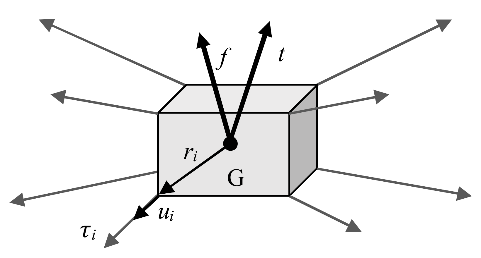
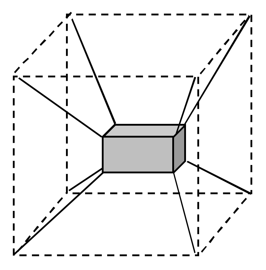
The computation of the suggested in this work is based on the solution of a linear programming problem involving cable tensions, cable tension limits and a novel representation of the so-called wrench matrix. The wrench matrix of a cable robot, also called structure matrix, is usually defined as the matrix relating the wrench exerted by the cable forces on the moving platform to the tension vector containing the cable forces (see Figure 1). It can be immediately recognized that in the most general case of a spatial cable robot driven by cables, it holds: , where the structure matrix takes the following form:
As schematically shown in Figure 1, vectors and are respectively the unit vector running along the ith cable, (oriented from the moving platform, that is, the box painted in grey in the scheme, towards the ith cable output point on the fixed frame) and the vector from the centre of mass (G) of the moving platform to the point where the ith cable is connected to the moving platform.
The structure matrix only allows computing the cable wrench exerted by the cables on the moving platform. In general, this is not the sole wrench applied to the moving platform. In order to compute the total wrench applied to the moving platform, external loading, including, for example, gravity force, should be taken into account. In the previous definition of vectors and are respectively the overall forces and torques exerted on the moving platform by the cables and the external forces. To account explicitly for external forces, a novel definition for the wrench matrix (denoted by ) is introduced, which is obtained by simply aggregating the structure matrix and the external wrench :
Once the matrix definition of in Equation (2) is introduced, it is possible to develop cable robot performance analysis following a well-established approach. It is common knowledge that in the performance analysis of parallel manipulators it has been proved convenient to split Jacobian matrices into their “translational” and “rotational” parts [13] in order to evaluate independently the translational and rotational capabilities of parallel robots. By applying the same idea to the novel definition of the wrench matrix of a cable robot, it is here suggested to split into two parts, namely and (where ) to analyze separately force and torque exertion capabilities.
The proposed analysis is particularly useful when it is referred to a specific direction of interest not necessarily coinciding with an axis of the absolute reference frame. Since the force and torque components in vector are expressed in an absolute reference frame, in order to refer the evaluation to a specific direction , a rotation matrix can be introduced to define such a direction of interest univocally in the absolute reference frame adopted [13]. Once the direction is defined, symbols and are used to denote two orthogonal directions which, combined with , provide a Cartesian reference frame. The following expressions can be adopted to rotate matrices and :
Then, for example, the WEC of a fully constrained cable robot can be expressed in terms of the maximum force that can be exerted along the direction d while keeping bounded cable tensions and given values of the other wrench components. Such a WEC may be referred to as , since it involves a force evaluation along a direction of interest and can be computed by solving the following linear programming problem (henceforth, the symbol stands for the component-wise inequality):
Similarly, if the torque exertion capability along a direction d is to be evaluated, the can be computed by simply solving the linear programming problem stated as follows:
In general, a default value for should be because, when a cable robot is designed, a practical need may consist in predicting the maximum force that can be exerted along a prescribed direction while keeping null wrench components, both in terms of forces and torques, along the other directions. For example, this is the case when it is necessary to accelerate the moving platform along a specific direction belonging to a path, while keeping the platform orientation unaltered. This is coherent with the typical investigation objectives presented at the beginning of this section.
The possibility of meeting imposed requirements on the full set of values of the wrench components excluding the one which is maximized, may only be assured in fully actuated and redundant cable robots. Conversely, when a cable robot is underactuated this is generally impossible. Nonetheless, a suitable redefinition of the linear programming problem allows extending the application of the WEC index to such cable robots. Indeed, in underactuated cable robots it is impossible to apply the proposed optimization unless enough equations in the linear problem are removed. This is a consequence of the fact that it is impossible to assign finite values to all the components but only to of them, where is the number of active cables. Instead of just removing from the linear programming problem the proper number of equality constraints, we suggest replacing them with inequality constraints imposing upper and lower bounds to the wrench components to which finite values cannot be assigned. As an example, consider the problem statement in Equation (6) which refers to a spatial cable robot with 6 dofs driven by 3 active cables: in order to compute a , finite values are assigned only to 2 force components () while the torque components of the overall wrench are limited by upper and lower bounds ().
In particular, if we compare Equation (6) with the formulation in Equation (4), it is apparent that the constraints in the form of equalities removed from have been replaced by a suitable set of constraints in the form of inequalities .
The presented extension of the WEC definition to underactuated cable robots addresses a more general problem and gives the opportunity to make comparisons among considerably different robot topologies keeping a goal-driven approach.
Equation (7) provides a conclusive and general formulation of the , suitable to any cable robot topology, where is a generalized force (i.e., can be either a force or torque component of the wrench vector projected along the direction of interest).
It is worth highlighting that in Equation (7) the dimensions of the matrices and are related to the cable robot topology and to the specific constraints defined for the analysis, reflecting operational requirements or specific features of the application. Let be the number of rows of matrix (i.e., the number of linear equality constraints). The following inequality must always hold: , where is the number of degrees of freedom of the moving platform and is the number of active cables. The inequality holding for reflects the practical need that the maximum number of equality constraints cannot exceed (being 1 the force or torque to be maximized and the overall number of wrench components) or in the case of underactuated robots. The maximum number of rows of matrix is instead equal to : since one inequality constraint can be introduced only if it is impossible, or not necessary for the given application, to provide constraints in equality form (i.e., if , then can be greater than zero). As for the number of columns of and , they are both equal to , that is, the size of the column vector .
In conclusion, the definition is strictly related to the constraints defined for the linear programming problem. Such constraints depend on the topology and on the application. It is important to notice that the formulation with inequality constraints can be always adopted, while exact values to all the wrench components apart from the one maximized (i.e., a formulation with a full set of equality constraints) can be imposed only with fully actuated or redundant robot.
3. Results of WEC Application
The computation presented in the previous section is here applied to the performance analysis of different topologies of cable robots. The objective is to provide a clear proof of the effectiveness and usefulness of the when it is employed at the design stage to find the regions of the workspace where a cable robot can best perform, or to compare different cable robot topologies or cable layouts. Three representative investigations are carried out, addressing:
- performance changes when robots have identical topologies but different cable layouts;
- performance changes when a cable robot topology is altered by increasing the number of active cables;
- performance evaluation of a spatial redundant cable robot.
3.1. Analysis of Cable Robots with Different Cable Layout
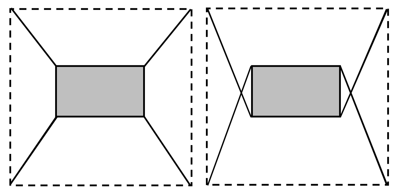
The first investigation concerns the group of cable robots shown in Figure 2 which comprises two redundant, planar and fully constrained cable robots with three dofs. The topology of the two robots analysed is identical but the points where cables are attached to the moving platform are different. Therefore, it is said that the cable layouts are different. As shown in Figure 2, the moving platform of the robots is rectangular () and is driven by four cables attached to the four platform vertices. The cable output points are located at the four vertices of a square. The coordinates (x, y) of the cable output points, expressed in a reference frame located at the square centroid, are: , , and . It is assumed that the platform moves in a horizontal plane (plane xy) and that the overall design of the platform the drive pulleys and the winches allow avoiding cable interference in the robot with crossed cables (Figure 2, on the right). For both the robots, the WEC can be computed by employing the formulations proposed in Equations (4) and (5), since both the robots are redundant and the platform can be fully constrained. In this example, it has been chosen to impose null wrench components () in the directions orthogonal to the one along which a force or torque is maximized. Additionally, since no external wrench is assumed to be applied on the platform, is a null vector too.
This choice is mainly meant to simplify the comparative analysis of the results. The maximization of all the three wrench components along the Cartesian axes , , has been investigated, that is, two forces acting along the positive directions of the axes x and y in the plane of motion and a torque about the positive direction of axis . For example, the , in terms of maximum torque about the positive direction of axis z, has been computed as follows:
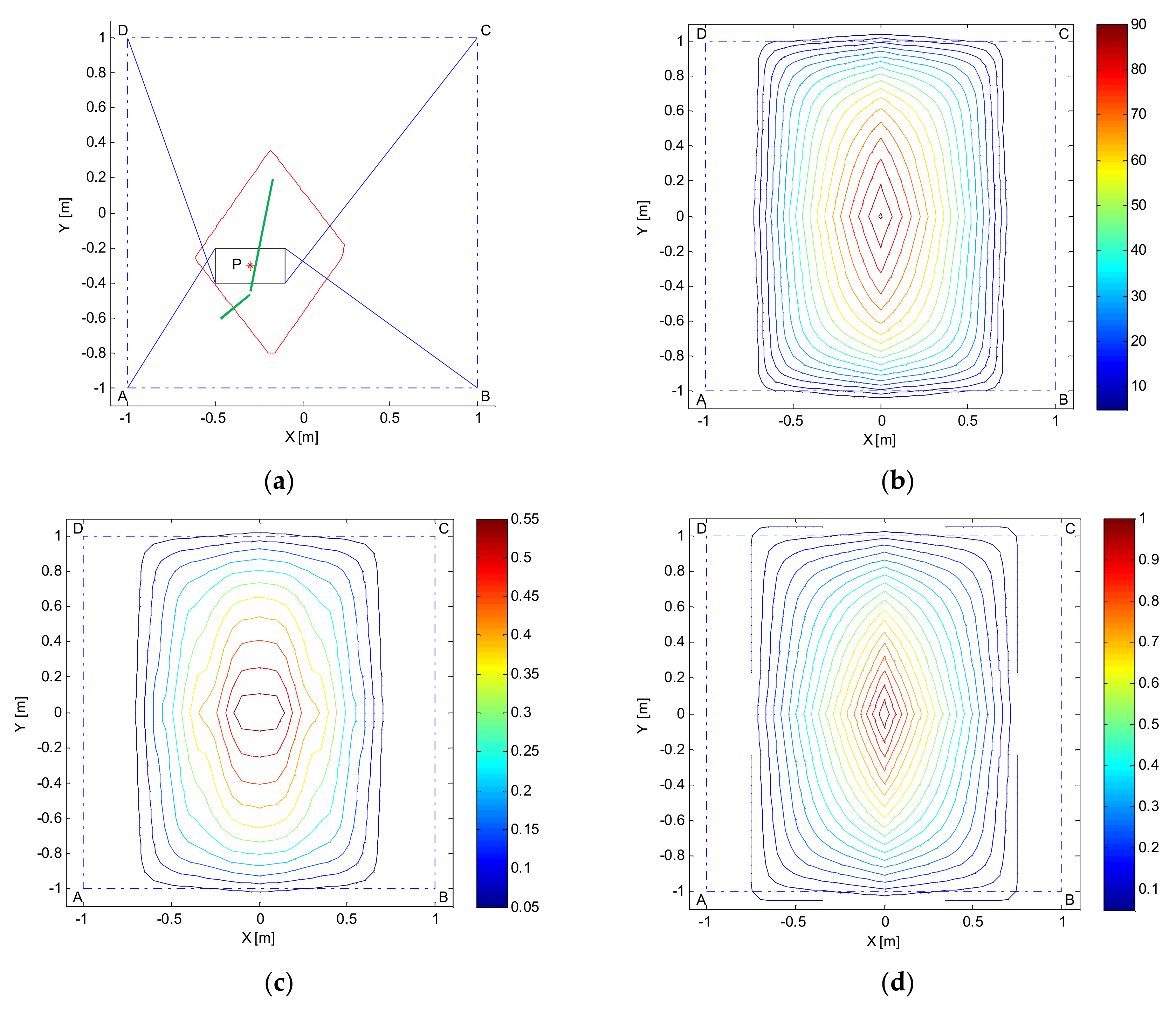
and , with the obvious meaning for symbols, have been computed similarly, always starting from the general formulation in Equation (7). Figure 3 collects all the results achieved. In Figure 3a, the sketches of the two cable robots can be recognized: dash-dotted lines are employed to connect the four cable output points; cables are represented by blue lines and the moving platform is depicted in solid black line. A green quadrangle delimits the Static Equilibrium Workspace (SEW) defined as the set of poses of the moving platform for which static equilibrium can be obtained while maintaining positive tensions in all the cables. The SEW has been computed with the shown orientation of the platform, that is, with the sides parallel to the x and y axes. As an example, the has been evaluated at point and refers to the force exertion capability along the positive direction of axis x (see the red arrows and the red numbers). As far as the range of tensions that can be resisted by the cables is concerned, without loss of generality, the maximum value has been set to while the minimum to . The arrows in bold line overlapped to the cables provide a scale representation of the cable forces which allow achieving the maximum force represented by the red arrow, whose module is the value, in , computed at point , which is also written below the red arrow.
While the results shown in Figure 3a refer to a single point P, the other plots of Figure 3 extend the analysis to the whole SEW: values have been computed only for the points belonging to the SEW and without altering the moving platform orientation. Figure 3b shows the values (in N), taken by the , while Figure 3c shows the . Finally, Figure 3d addresses the torque exertion capabilities of the robots by showing the (in ). In all the subplots from Figure 3b–d values are represented by isolines. The regions where the best performances are achieved can be immediately recognized: they are the ones where the isolines take the highest values (red lines). The comparison of the plots clearly highlights the superior performances that can be guaranteed by the robot with crossed cables. First of all, such a robot, which has a wider SEW too, guarantees the possibility of exerting high forces in the x and y directions in a wider subset of the SEW (notice the extension of the red and orange isolines in subplots (b) and (c)). In terms of very maximum values taken by the forces, there are no significant differences between the two robots. Conversely, the torque exertion capability is completely different (see subplot (d)): the behaviour of the robot with crossed cables is preferable since its cables can exert much higher torques.
The formulation can be further exploited to compute the minimum force values which can be guaranteed along any direction and at any point of the SEW and to perform an isotropy evaluation based on comparing such minimum force values with the very maximum ones that can be exerted at any point of the SEW. As an example, such analyses are presented in Figure 4 with reference to the sole robot with crossed cables. Figure 4a represents such a robot at a generic point .
The results of several repetitions of computations at point made considering different directions are collected and depicted through a red polygon which provides a scale representation of the maximum force that can be exerted along any radial direction d around . An angular resolution by 1° has been adopted to trace such a polygon, in other words, the polygon summarizes the output of 360 distinct computations. The wrench exertion capabilities of the robot referred to all the possible directions can be immediately inferred. The maximum and minimum exertable forces can also be easily found: they are traced in green lines.
If the same computation (i.e., repeated along any direction) is performed at each point of the SEW, a minimum force value which can be guaranteed irrespective of the direction can be found. Figure 4b shows such a value plotted through isolines. Getting such information at the design stage may obviously be of great practical usefulness.
If, at any point, the ratio between the minimum and maximum exertable forces (e.g., those traced in green lines for point in the subplot (a)) is computed, isotropy can be evaluated effectively. Figure 4c shows such ratios, which can be straightforwardly compared to the popular isotropy index called Tension Factor (TF), proposed in [17]. The TF is the ratio between the minimum and the maximum cable tension values achieved when the platform is in static equilibrium. In Figure 4d the TF computed at each point of the SEW has been plotted by isolines. Apparently, subplots (c) and (d) provide different indications in terms of robot isotropy, however it is the authors’ opinion that the one based on the WEC is more useful in practice, since the TF provides a measure of robot isotropy in the joint space, rather than in the Cartesian space.
3.2. Analysis of Cable Robots with Different Number of Cables
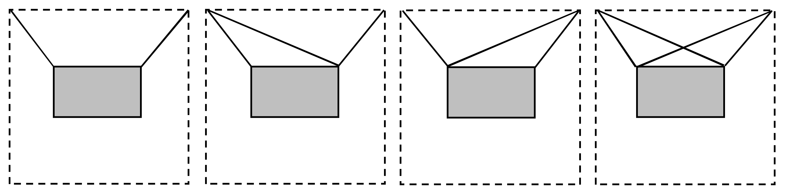
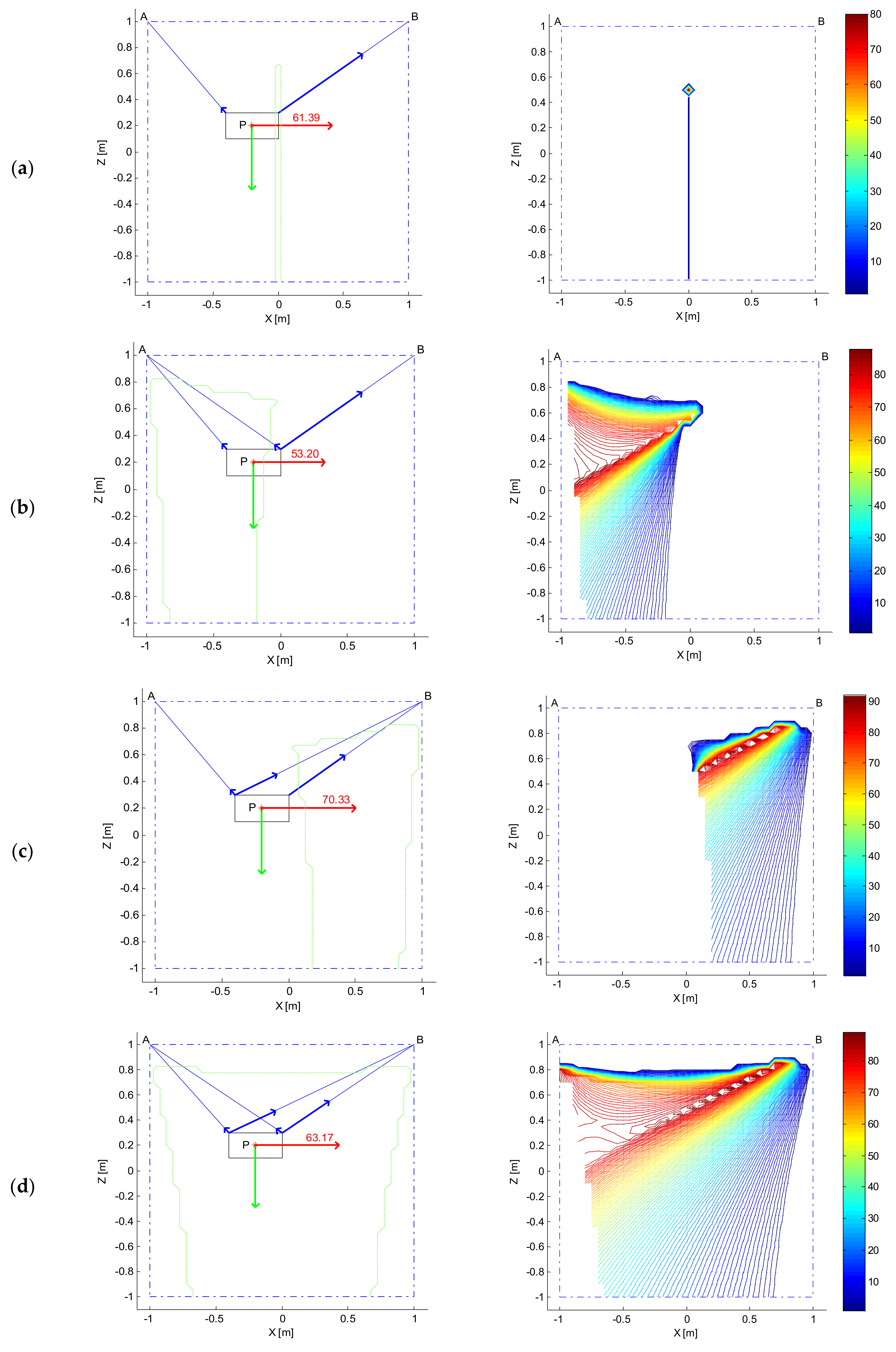
The second investigation concerns the group of cable robots shown in Figure 5 which comprises four underconstrained (or “cable suspended”) 3-dof cable robots differing in the number of cables and/or in the cable layout. The robots are assumed to move in a vertical plane, hence, their platforms are under the influence of gravity, which is essential to maintain tension in the cables in static conditions. Hence, for this comparison, the plane of motion is plane xz, the vertical one. The moving platforms of all the robots are assumed to be identical and share the same shape and dimensions of the of the cable robots presented in Section 3.1. The cables are all attached to the platform upper vertices. The cables output points are instead located at the two upper vertices of a square. The coordinates (x, z) of such points, expressed in a reference frame located at the square centroid, are: and . The first robot only has two cables and hence it is also underactuated. The other robots are instead fully actuated or redundant (i.e., with four cables).
By comparing the performances of these robots, the effect of increasing the number of active cables can be appreciated, also in relation to the cable layout adopted. This is the objective of such a comparative analysis, whose results are collected in Figure 6. Robot performances are compared by referring to the obtained by assuming that:
- cable tensions are to be kept in the range ;
- a null overall torque must be exerted on the platform;
- a limited vertical force in the upwards direction must be applied to the platform. The lower and upper bounds of such a vertical force have been set equal to, respectively, .
The mentioned constraints are coherent with the field of application where cable suspended robots are very likely to be employed in the future: high speed pick and place manipulations (e.g., over-the-belt packaging). Indeed, if a cable suspended robot has to be employed for such tasks, it is of apparent interest evaluating which is the maximum horizontal force that can be exerted on the platform and hence applied to the picked object, while keeping a null torque on it (not to induce rotations) and a bounded upward force (if a given force value in the vertical direction cannot be set due to the limited number of cables available). Not only does imposing an upward force meet the basic requirement of lifting the picked objects during the manipulation (a lower bound higher than zero could be imposed to this purpose) but setting an upper bound could allow preventing the load from being dropped at the start of the motion.
In other words, the upper bound on the vertical force could reflect a limitation to the maximum vertical acceleration. In the comparative analysis, although the sole 2-cable robot is actually underactuated, identical constraints in the form of inequalities have been set for all WEC computations to make the comparison between different cable robot topologies fair. The problem is therefore stated as follows for all the robots:
Generally speaking, the can be computed at any point achievable by the moving platform statically or dynamically. In the subplots on the left of Figure 6, the computation is referred to a generic point . The lines employed in these plots have the same meaning of the corresponding ones in Figure 4a. Here, however, a vertical green arrow is also adopted to provide a scale representation of the external wrench : the force of gravity acting on the platform. The mass of the platform has been set equal to .
In the subplots on the right of Figure 6, the analysis has been extended to all the points of the Statically Feasible Workspace (SFW) defined as the set of the mobile platform poses for which static equilibrium against gravity can be obtained using a limited range of cable tensions [3].
The SFWs of all the robots, computed keeping the platform horizontal, are represented in the subplots on the left of Figure 6, for clarity, delimited by green solid lines. The SFWs have been geometrically bounded by the square box with vertices at and . The isolines in the plots highlight the greatly different behaviors of the four cable driven robots: while for the underactuated robot (subplot (a)) it is possible to find a solution to the problem stated in Equation (9) in just one point of the SFW, by increasing the number of active cables, the force exertion capabilities improve considerably. The subplots (b) and (c) prove that, for the given problem of maximizing a rightward force, the two fully actuated robots behave very differently in their SFWs. The SFWs of the robots are very different (basically symmetrical about the z axis) and not overlapped, which complicates performing a straightforward comparison between the robots. Nonetheless, the plots provide clear hints about the regions where these robots can best perform. Clearly, the most effective cable layout could be identified once the geometrical features of the tasks to be executed and of the workcell were known: in general, the cable arrangement of Figure 6b seems preferable since the takes high values in a wider region of the workspace. Finally, in Figure 6d, the of the redundant robot is plotted. Obviously, the availability of a fourth cable allows extending the SFW and improving the performances within it. In particular, the rightward force exertion capability shows that this robot merges the benefits of the fully actuated robots discussed earlier, at the expense of an increased cost, design complexity and cable obstruction in the workspace.
3.3. Analysis of a 6-dof Overconstrained Spatial Cable Robot
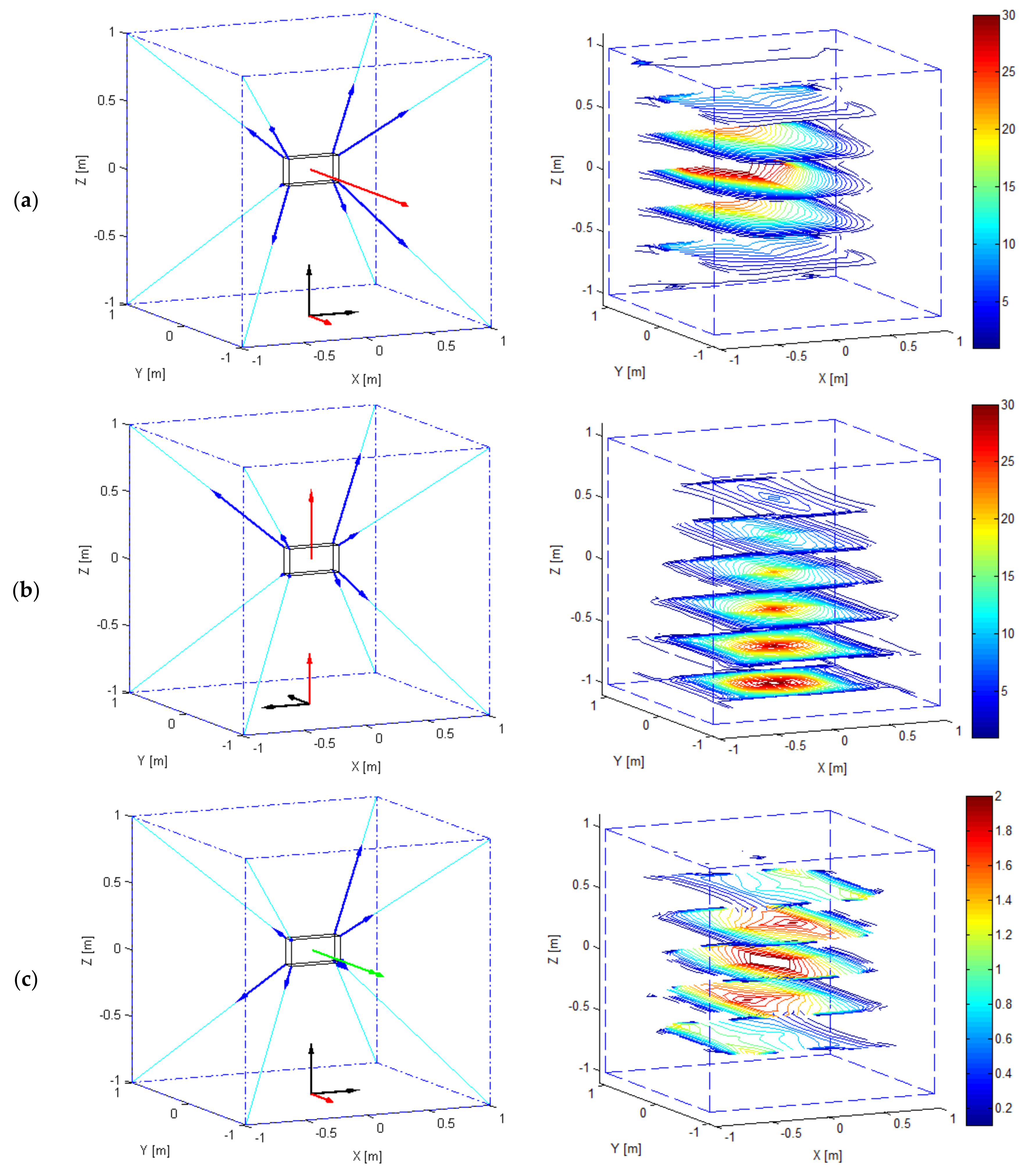
The third investigation concerns the cable robot shown in Figure 7 which is a spatial redundant cable robot with six degrees of freedom. The robot design and cable layout recall those of several prototypes developed worldwide [1,2]. The moving platform of the robot is a parallelepiped () that weighs and is driven by eight cables attached to the eight platform vertices. The cable output points are located at the eight vertices of a cube. The coordinates (x, y, z) of the cable output points, expressed in a reference frame located at the cube centroid, are: , , , , , , and .
For this robot, the WEC can be computed by employing the formulations proposed in Equations (4) and (5), since the robot is redundant and the platform can be fully constrained. Also in this case, it has been chosen to impose null wrench components () in the directions orthogonal to the one along which a force or torque is maximized. Additionally, since gravity force is applied to the platform, the third row of the vector is equal to the gravity force, while the other rows contain null values. The maximization of three representative wrench components along the Cartesian axes x, y, z has been investigated. In particular, it has been chosen to maximize the two forces acting along, respectively, the negative direction of the y axis and the positive direction of z axis. Finally, the torque acting about the negative direction of the axis y has been analysed. As an example, the WEC, in terms of maximum torque about the negative direction of axis y, has been computed as follows:
where the direction is achieved by setting the matrix defined in Equation (3) equal to an elementary rotation matrix of −90 degrees about the z axis ().
Figure 8 collects the results achieved. For the sake of clarity, in the left subplots of Figure 8, the origin of the rotated reference frame is set at point (0 m, 0 m, −1 m) and the direction is highlighted by means of a red arrow. The results shown in the subplots on the left of Figure 8 refer to a single point . Dash-dotted lines are employed to connect the eight cable output points and hence to represent the robot typical workspace; cables are represented by light-blue lines and the moving platform is depicted in solid black line. As an example, the has been evaluated at point . As far as the range of tensions that can be resisted by the cables is concerned, without loss of generality, the maximum value has been set to while the minimum to . The arrows in bold blue line overlapped to the cables provide a scale representation of the cable forces which allow achieving the maximum force/torque represented by the red (in case of forces) or green (in case of torque) arrows. In the subplots on the right, each analysis is extended to the whole SEW: only the results achieved in some representative horizontal planes of the SEW are represented for clarity. As usual, in these subplots WEC values are represented by isolines, the red ones identifying the regions where the best performances are achieved (i.e., where the highest WEC values are achieved). Figure 8a shows the values (in ), taken by the , while Figure 8b shows the (). Finally, Figure 8c addresses the torque exertion capabilities of the robot by showing the (Nm).
As it has already stated for planar cable robots, the computed forces or torques can be exerted statically by the end-effector on the environment or alternatively they can be interpreted as forces or torques that the cables can apply to the end-effector to accelerate it. According to the latter interpretation, the results plotted give immediate evidence of the workspace locations where the highest dynamic performances can be achieved.
4. Conclusions
A comprehensive evaluation of the performances of any cable driven robot can be carried by the proposed performance index named Wrench Exertion Capability (), which allows evaluating the maximum force or torque a cable robot can exert along a direction of interest. The WEC accounts explicitly for the intrinsic cable tension limits and for the constraints which can be imposed to the wrench components that are not maximized.
A linear programming problem is solved to compute the . The problem makes use of suitable partitions of a novel definition of the wrench matrix which has been introduced to simplify the inclusion of external wrenches in the analysis. The formulation proposed is general enough to allow analyzing redundant, fully actuated and underactuated spatial cable robots. To this purpose, the use of constraints in both the form of equalities and inequalities has been suggested and discussed.
Finally, by a set of representative examples, it has been proved that the can be adopted to carry out complete and effective evaluations of the performances of cable robots either in absolute or comparative terms.
Author Contributions
G.B. and A.T. conceived the study and designed the experiments; G.B. performed the experiments; G.B. and A.T. analyzed the data; G.B. and A.T. wrote the paper.
Conflicts of Interest
The authors declare no conflict of interest.
References
- Albus, J.S.; Bostelman, R.; Dagalakis, N.G. The NIST ROBOCRANE. J. Robot. Syst. 1993, 10, 709–724. [Google Scholar] [CrossRef]
- Pott, A.; Mütherich, H.; Kraus, W.; Schmidt, V.; Miermeister, P.; Verl, A. IPAnema: A family of Cable-Driven Parallel Robots for Industrial Applications. In Cable-Driven Parallel Robots; Bruckmann, T., Pott, A., Eds.; Springer: Berlin/Heidelberg, Germany, 2013; pp. 119–134. [Google Scholar]
- Trevisani, A. Planning of dynamically feasible trajectories for translational, planar, and underconstrained cable-driven robots. J. Syst. Sci. Complex. 2013, 26, 695–717. [Google Scholar] [CrossRef]
- Abdolshah, S.; Zanotto, D.; Rosati, G.; Agrawal, S. Performance evaluation of a new design of cable-suspended camera system. In Proceedings of the International Conference on Robotics and Automation (ICRA), Singapore, 29 May–3 June 2017; pp. 3728–3733. [Google Scholar]
- Trevisani, A. Underconstrained planar cable-direct-driven robots: A trajectory planning method ensuring positive and bounded cable tensions. Mechatronics 2010, 20, 113–127. [Google Scholar] [CrossRef]
- Carricato, M.; Abbasnejad, G. Direct geometrico-static analysis of under-constrained cable-driven parallel robots with 4 cables. In Cable-Driven Parallel; Bruckmann, T., Pott, A., Eds.; Springer: Berlin/Heidelberg, Germany, 2013; pp. 269–285. [Google Scholar]
- Zi, B.; Sun, H.; Zhang, D. Design, analysis and control of a winding hybrid-driven cable parallel manipulator. Robot. Comput. Integr. Manuf. 2017, 48, 196–208. [Google Scholar] [CrossRef]
- Williams, R.L.; Gallina, P.; Vadia, J. Planar translational cable direct driven robots. J. Robot. Syst. 2003, 20, 107–120. [Google Scholar] [CrossRef]
- Rosati, G.; Secoli, R.; Zanotto, D.; Rossi, A.; Boschetti, G. Planar robotic systems for upper-limb post-stroke rehabilitation. In Proceedings of the ASME 2008 International Mechanical Engineering Congress and Exposition (IMECE 2008), Boston, MA, USA, 31 October–6 November 2008. [Google Scholar]
- Hernandez, E.; Valdez, S.I.; Carbone, G.; Ceccarelli, M. Design optimization of a cable-driven parallel robot in upper arm training-rehabilitation processes. Mech. Mach. Sci. 2018, 54, 413–424. [Google Scholar]
- Surdilovic, D.; Radojicic, J.; Krüger, J. Geometric stiffness analysis of wire robots: A mechanical approach. In Cable-Driven Parallel Robots; Bruckmann, T., Pott, A., Eds.; Springer: Berlin/Heidelberg, Germany, 2013; pp. 389–404. [Google Scholar]
- Abdolshah, S.; Shojaei Barjuei, E. Linear quadratic optimal controller for cable-driven parallel robots. Front. Mech. Eng. 2015, 10, 344–351. [Google Scholar] [CrossRef]
- Merlet, J.P. Jacobian, manipulability, condition number, and accuracy of parallel robots. ASME J. Mech. Des. 2006, 128, 199–206. [Google Scholar] [CrossRef]
- Gao, F.; Liu, X.; Gruver, W.A. Performance Evaluation of Two-degree-of-freedom Planar Parallel Robots. Mech. Mach. Theory 1998, 33, 661–668. [Google Scholar] [CrossRef]
- La Mura, F.; Romanò, P.; Fiore, E.; Giberti, H. Workspace Limiting Strategy for 6 DOF Force Controlled PKMs Manipulating High inertia Objects. Robotics 2018, 7, 10. [Google Scholar] [CrossRef]
- Seriani, S.; Gallina, P.; Gasparetto, A. A performance Index for Planar Repetitive Workspace Robots. J. Mech. Robot. 2014, 6, 031005. [Google Scholar] [CrossRef]
- Rosati, G.; Gallina, P. Manipulability of a planar wire driven active design. Mech. Mach. Theory 2002, 37, 215–228. [Google Scholar]
- Pusey, J.; Fattah, A.; Agrawal, S.; Messina, E. Design and workspace analysis of a 6-6 cable suspended parallel robot. Mech. Mach. Theory 2004, 39, 761–778. [Google Scholar] [CrossRef]
- Khalilpour, S.A.; Lololei, A.Z.; Taghirad, H.D.; Masouleh, M.T. Feasible Kinematic Sensitivity in Cable Robots Based on Interval Analysis. In Cable Driven Parallel Robots; Bruckmann, T., Pott, A., Eds.; Springer: Berlin/Heidelberg, Germany, 2013; pp. 223–249. [Google Scholar]
- Cardou, P.; Bouchard, S.; Gosselin, C. Kinematic-Sensitivity Indicies for Dimensionally Nonhomogeneous Jacobian Matrices. IEEE Trans. Robot. 2010, 26, 166–173. [Google Scholar] [CrossRef]
- Pham, C.B.; Yeo, S.H.; Yang, G.; Chen, I.-M. Workspace analysis of fully restrained cable-driven manipulators. Robot. Auton. Syst. 2009, 57, 901–912. [Google Scholar] [CrossRef]
- Barbazza, L.; Oscari, F.; Minto, S.; Rosati, G. Trajectory planning of a suspended cable driven parallel robot with reconfigurable end effector. Robot. Comput. Integr. Manuf. 2017, 48, 1–11. [Google Scholar] [CrossRef]
- Abdolshas, S.; Zanotto, D.; Rosati, G.; Agrawal, S.K. Optimizing Stiffness and Dexterity of Planar Adaptive Cable-Driven Parallel Robots. ASME J. Mech. Robot. 2017, 9, 031004:1–031004:11. [Google Scholar]
- Boschetti, G.; Trevisani, A. Performance evaluation for cable direct driven robot. In Proceedings of the 12th Biennial Conference on Engineering Systems Design and Analysis ESDA 2014, Copenhagen, Denmark, 251–27 June 2014. [Google Scholar]
- Boschetti, G.; Trevisani, A. On the Use of the Wrench Exertion Capability as a Performance Index for Cable Driven Robot. In Proceedings of the Thematic Conference on Multibody Dynamics ECCOMAS 2015, Barcelona, Spain, 29 June–2 July 2015. [Google Scholar]
- Berti, A.; Gouttefarde, M.; Carricato, M. Dynamic recovery of cable-suspended parallel robots after a cable failure. In Advances in Robot Kinematics 2016; Lenarčič, J., Merlet, J.P., Eds.; Springer: Cham, Switzerland, 2018; Volume 4, pp. 331–339. [Google Scholar]
- Boschetti, G.; Passarini, C.; Trevisani, A. A recovery strategy for cable driven robots in case of cable failure. Int. J. Mech. Control 2017, 18, 41–48. [Google Scholar]
Figure 1.
Schematic representation of the moving platform of a spatial cable robot and of the vectors involved in the computation of the wrench exerted by the cables on the platform.
Figure 1.
Schematic representation of the moving platform of a spatial cable robot and of the vectors involved in the computation of the wrench exerted by the cables on the platform.

Figure 2.
Two cable robots with same topology and different cable layout.

Figure 3.
Wrench Exertion Capability (WEC) comparison for the two redundant cable robots sketched in Figure 2 in terms of analysis at point P (a), (b), (c) and (d).
Figure 3.
Wrench Exertion Capability (WEC) comparison for the two redundant cable robots sketched in Figure 2 in terms of analysis at point P (a), (b), (c) and (d).

Figure 4.
Scale representation of the maximum force that can be exerted along any direction at a point (a); minimum guaranteed force (b); isotropy evaluation (c) and Tension Factor (d).
Figure 4.
Scale representation of the maximum force that can be exerted along any direction at a point (a); minimum guaranteed force (b); isotropy evaluation (c) and Tension Factor (d).

Figure 5.
Cable suspended robots investigated comparatively by the .

Figure 6.
(a–d) for each of the different topologies of cable suspended robots presented in Figure 5. are either computed at a single point (plots on the left) or throughout the statically feasible workspace (SFW) (plots on the right).
Figure 6.
(a–d) for each of the different topologies of cable suspended robots presented in Figure 5. are either computed at a single point (plots on the left) or throughout the statically feasible workspace (SFW) (plots on the right).

Figure 7.
The 6-dof overconstrained spatial cable robot investigated.

Figure 8.
(a) (b) and (c) of the spatial cable robot presented in Figure 7. are either computed at a single point (plots on the left) or throughout the static equilibrium workspace (SEW) (plots on the right).
Figure 8.
(a) (b) and (c) of the spatial cable robot presented in Figure 7. are either computed at a single point (plots on the left) or throughout the static equilibrium workspace (SEW) (plots on the right).

© 2018 by the authors. Licensee MDPI, Basel, Switzerland. This article is an open access article distributed under the terms and conditions of the Creative Commons Attribution (CC BY) license (http://creativecommons.org/licenses/by/4.0/).
Share and Cite
MDPI and ACS Style
Boschetti, G.; Trevisani, A. Cable Robot Performance Evaluation by Wrench Exertion Capability. Robotics 2018, 7, 15. https://doi.org/10.3390/robotics7020015
AMA Style
Boschetti G, Trevisani A. Cable Robot Performance Evaluation by Wrench Exertion Capability. Robotics. 2018; 7(2):15. https://doi.org/10.3390/robotics7020015
Chicago/Turabian StyleBoschetti, Giovanni, and Alberto Trevisani. 2018. "Cable Robot Performance Evaluation by Wrench Exertion Capability" Robotics 7, no. 2: 15. https://doi.org/10.3390/robotics7020015
Note that from the first issue of 2016, this journal uses article numbers instead of page numbers. See further details here.