
A Performance Improvement Method for Low-Cost Land Vehicle GPS/MEMS-INS Attitude Determination

Abstract
:1. Introduction
2. GPS Attitude Determination with the CLAMBDA
3. Improved Attitude Determination Method for Single Frequency and Single Epoch
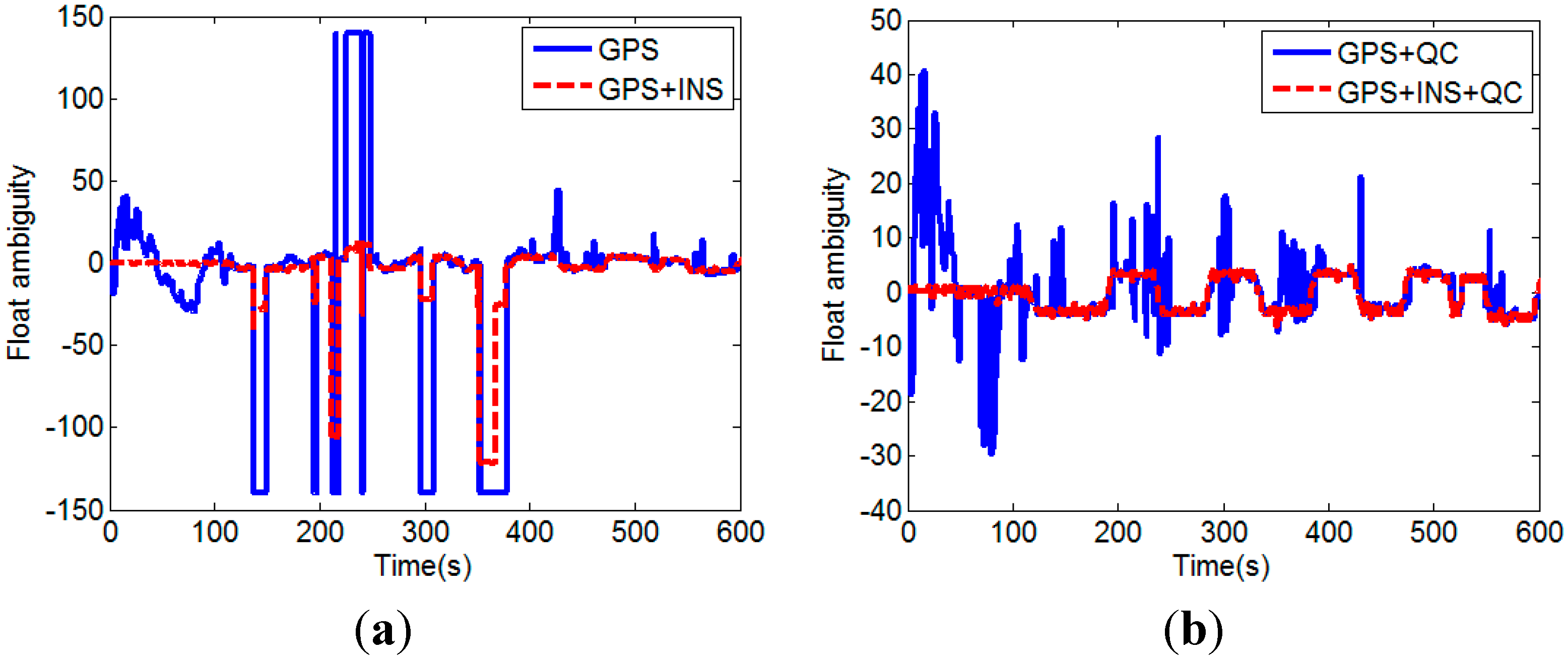
3.1. Float Solution by GPS/INS Augmented Measurements
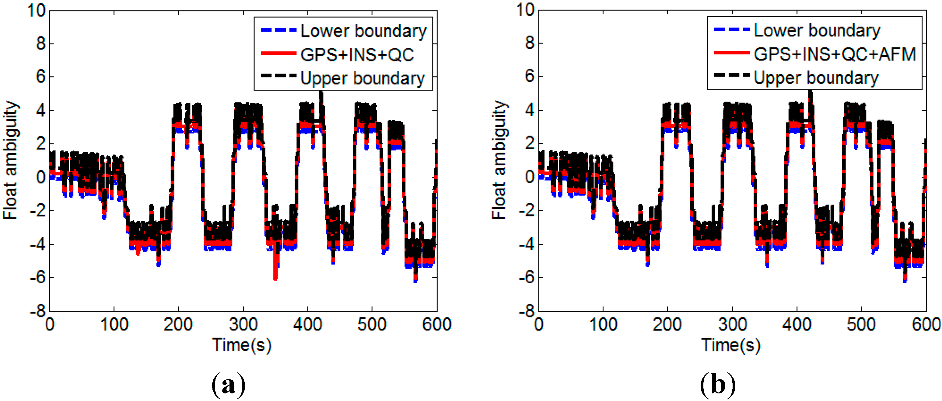
3.2. Quality Assessment of Float Solution
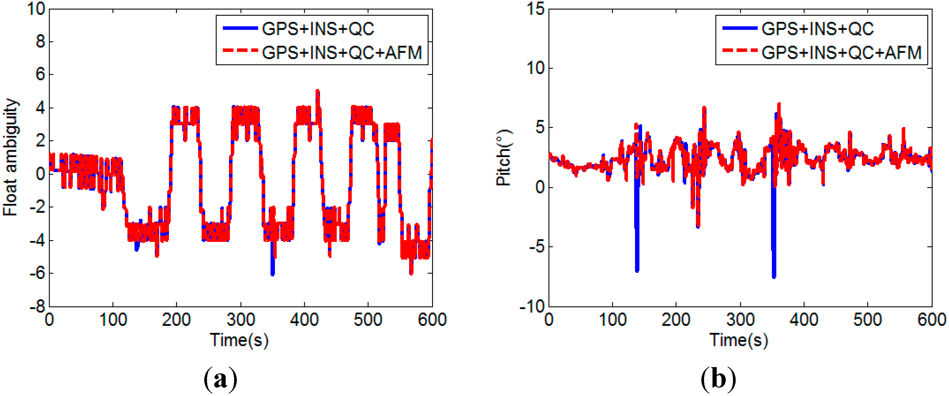
3.3. Float Solution with INS-Aided AFM
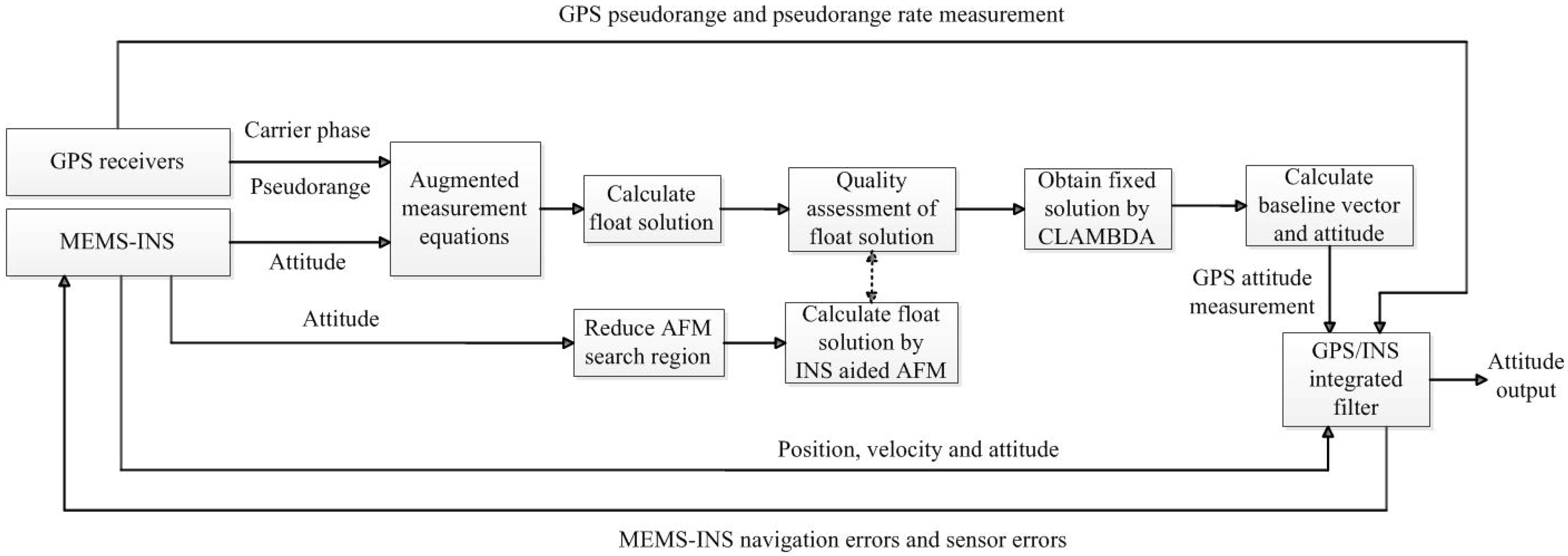
3.4. The Implementation of the Proposed Method

4. GPS/MEMS-INS Integrated Filter
4.1. State Equations of the Integrated Filter
4.2. Measurement Equations of the Integrated Filter
5. Experiment Test Results

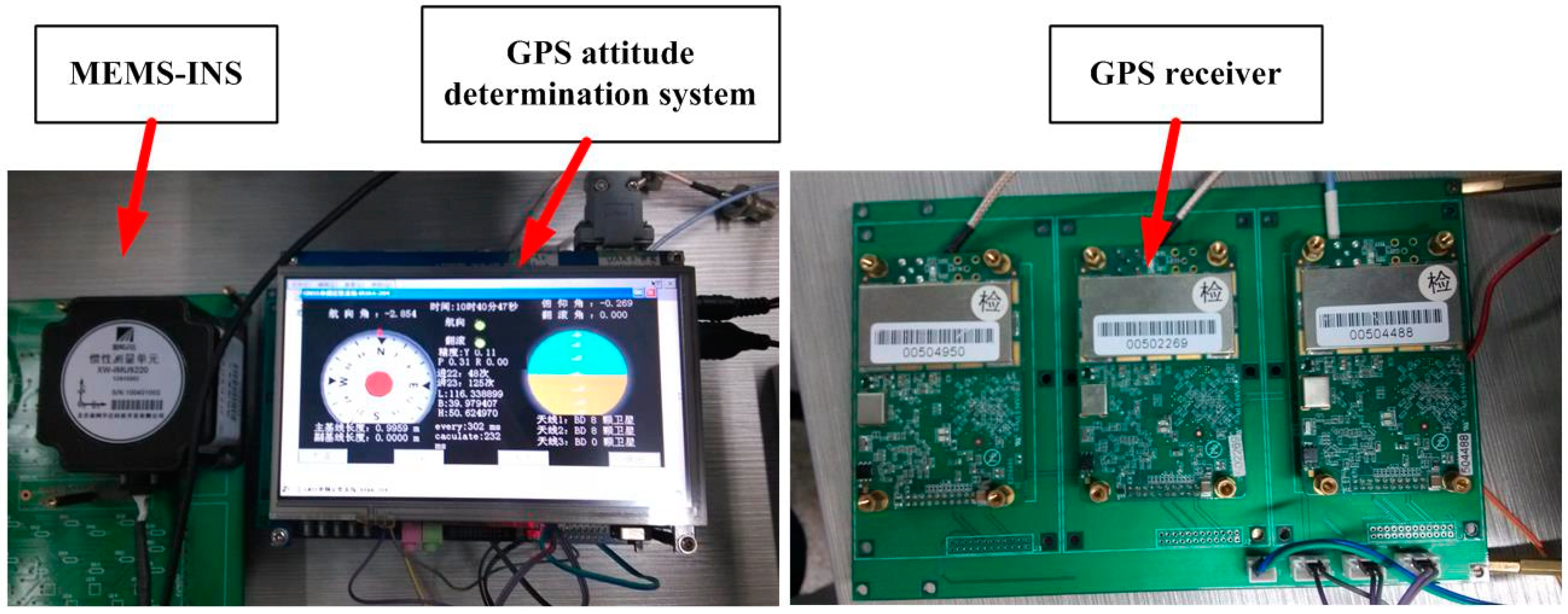
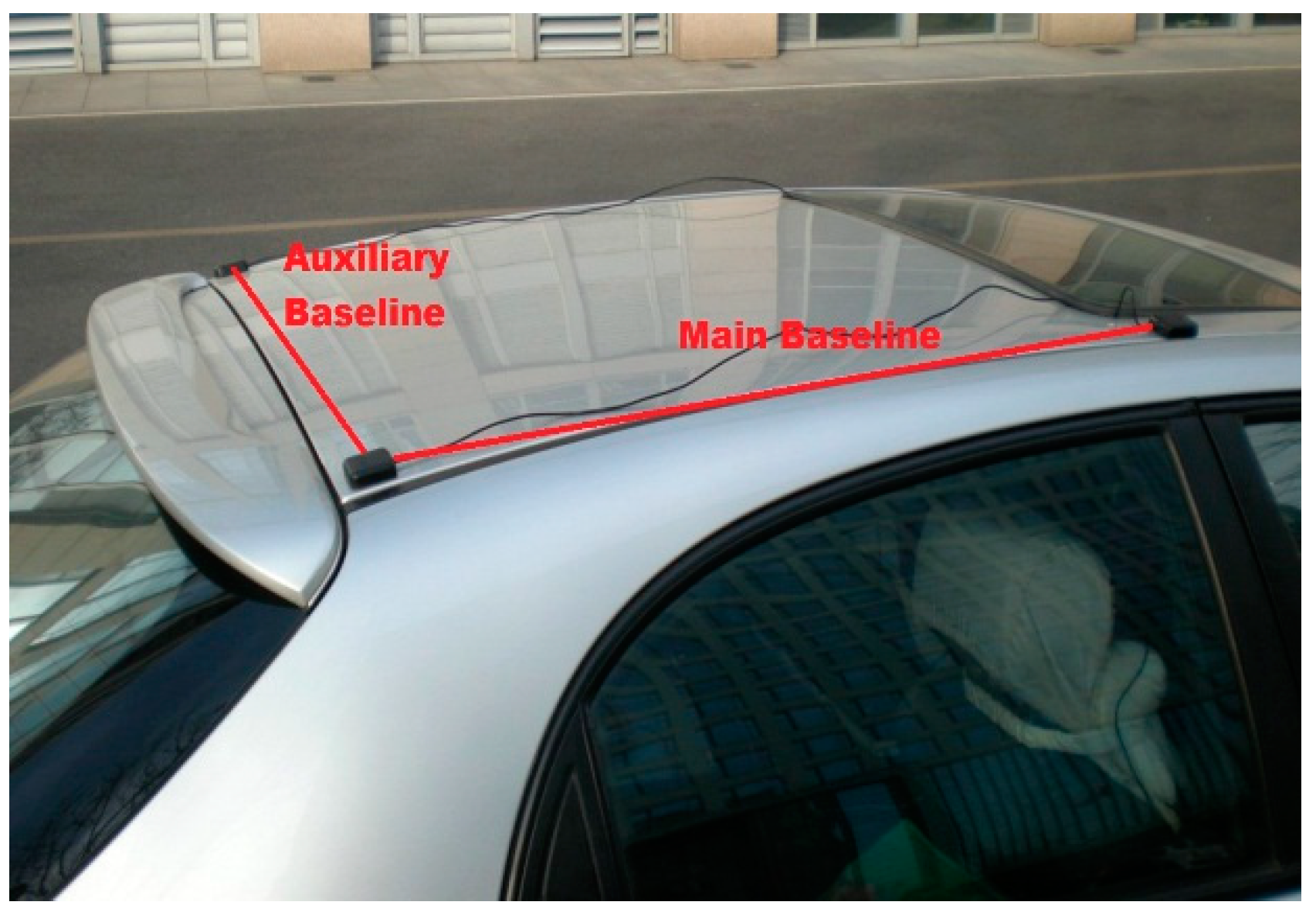
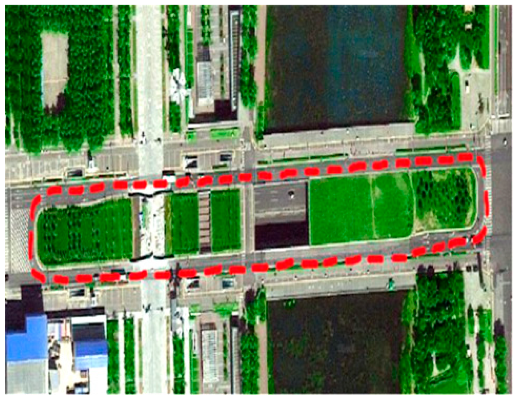
5.1. Test Settings


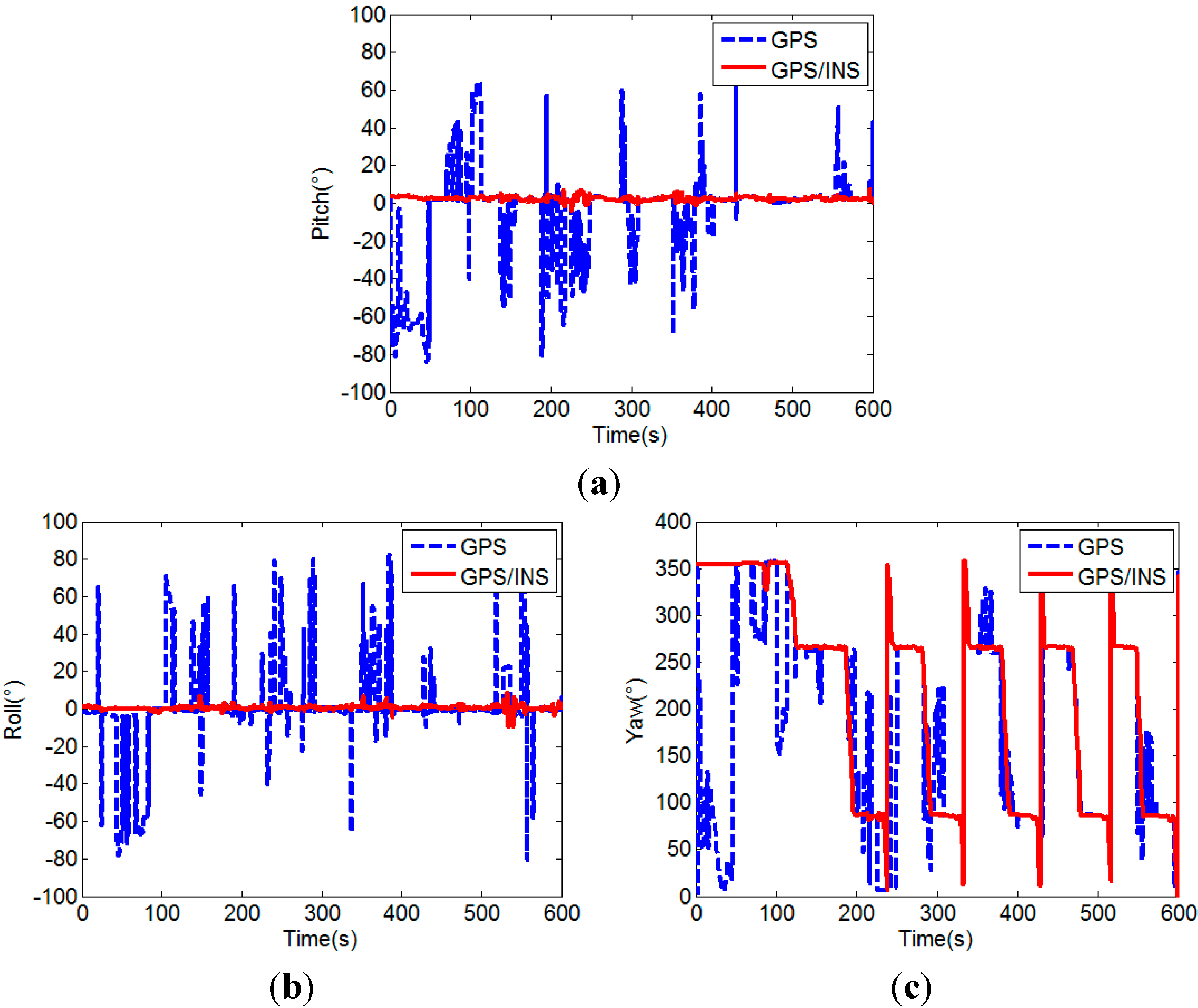
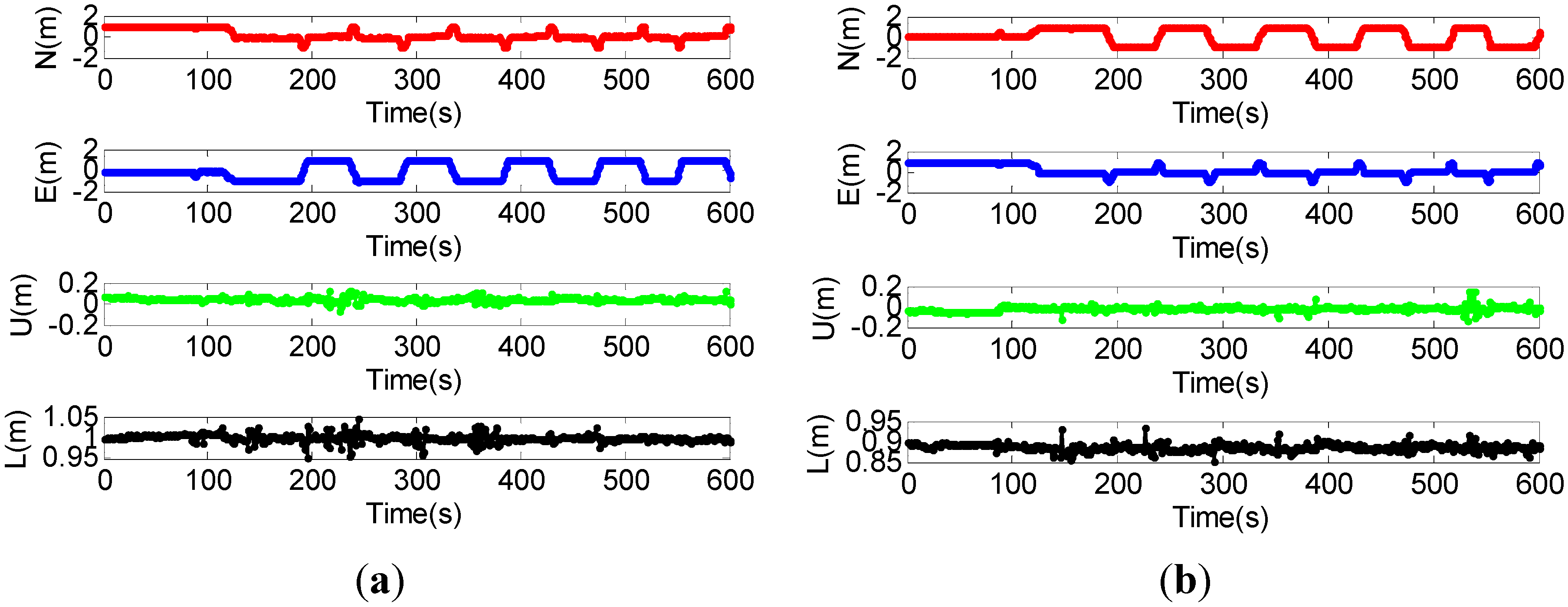
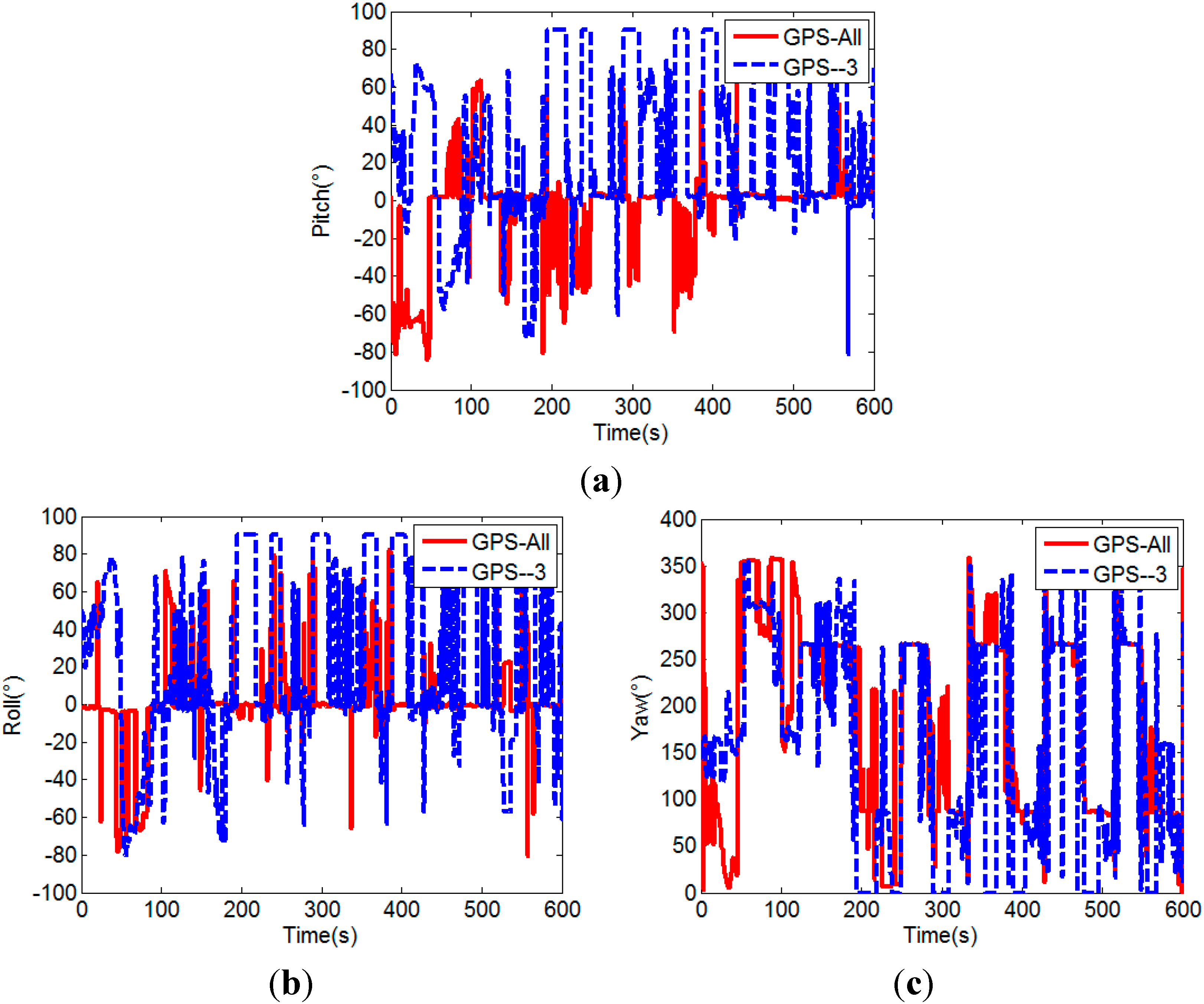
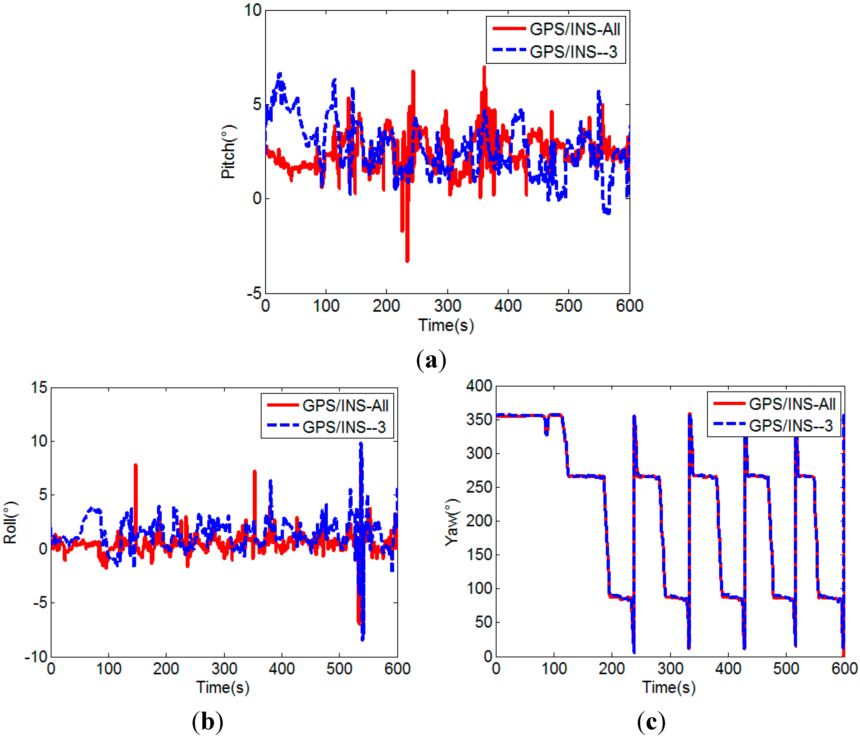
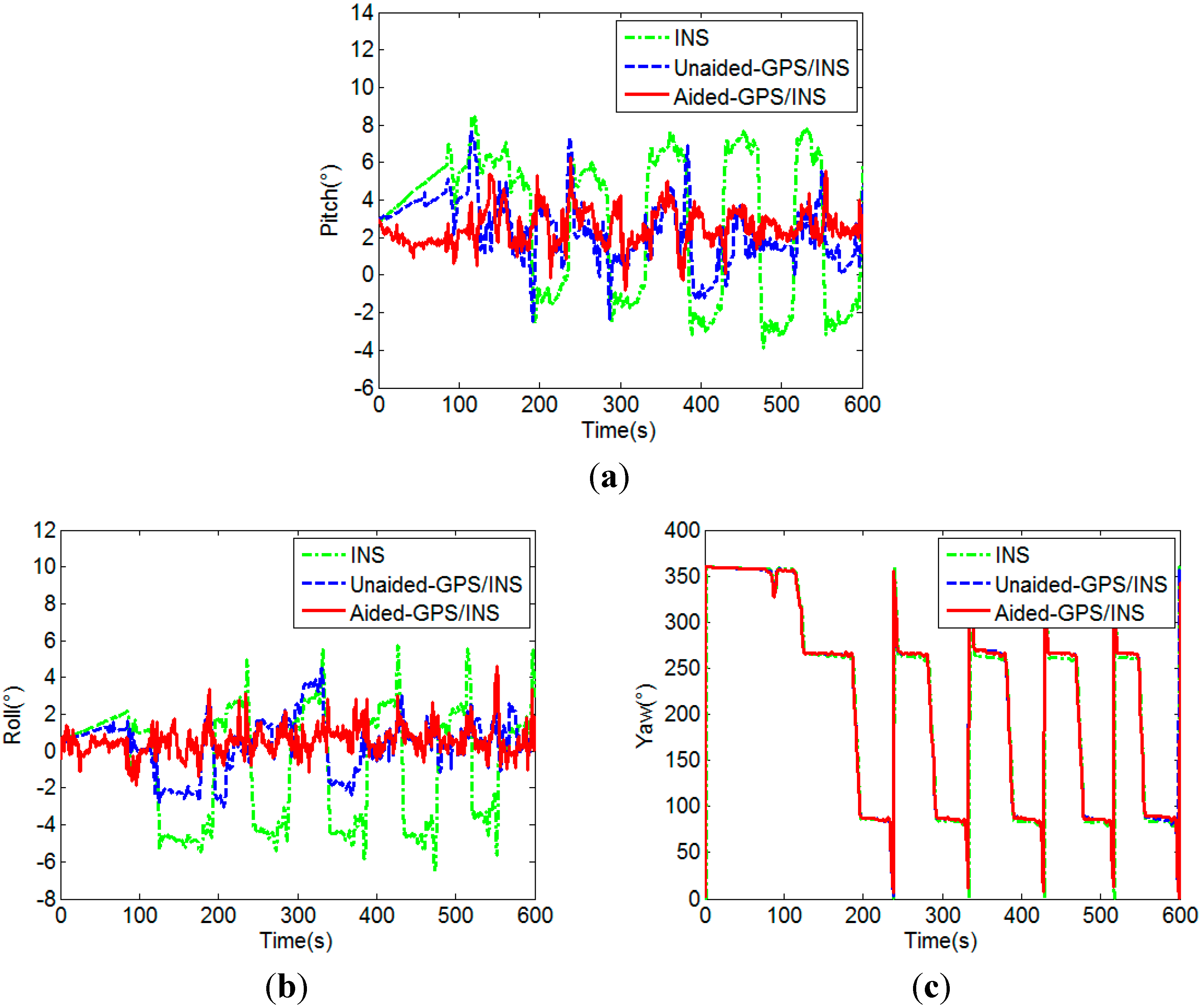
5.2. Test Results


| Unaided GPS | MEMS-INS Aided GPS | |
|---|---|---|
| Main baseline | 72.83% | 99.00% |
| Auxiliary baseline | 70.67% | 98.83% |


| Unaided GPS (All/-3) | MEMS-INS Aided GPS (All/-3) | |
|---|---|---|
| Main baseline | 72.83%/49.50% | 99.00%/97.83% |
| Auxiliary baseline | 70.67%/45.67% | 98.83%/97.67% |

| MEMS-INS | Unaided Integration (All/-3) | Aided Integration (All/-3) | |
|---|---|---|---|
| Pitch (°) | 3.7920 | 1.9344/2.6892 | 1.0823/1.4216 |
| Roll (°) | 3.0991 | 1.5886/2.6534 | 1.0626/1.4209 |
6. Conclusions
Acknowledgments
Author Contributions
Conflicts of Interest
References
- Yong, L.; Mahmoud, E.; Andrew, G.D. Attitude determination by integration of MEMS inertial sensors and GPS for autonomous agriculture applications. GPS Solut. 2012, 16, 41–52. [Google Scholar] [CrossRef]
- Wu, Z.; Yao, M.; Ma, H.; Jia, W. Improving accuracy of the vehicle attitude estimation for low-cost INS/GPS integration aided by the GPS-measured course angle. IEEE Trans. Intell. Transp. Syst. 2013, 2, 553–564. [Google Scholar] [CrossRef]
- Urban, M.; Manfred, M. Attitude estimation for vehicles with partial inertial measurement. IEEE Trans. Veh. Technol. 2011, 4, 1496–1504. [Google Scholar]
- Wang, B.; Miao, L.; Wang, S.; Shen, J. An integer ambiguity resolution method for the global positioning system (GPS)-based land vehicle attitude determination. Meas. Sci. Technol. 2009, 20, 075108. [Google Scholar] [CrossRef]
- Bevly, D.M.; Ryu, J.; Gerdes, J.C. Integrating INS sensors with GPS measurements for continuous estimation of vehicle sideslip, roll, and tire cornering stiffness. IEEE Trans. Intell. Transp. Syst. 2006, 7, 483–493. [Google Scholar] [CrossRef]
- Hwang, D.H.; Oh, S.H.; Lee, S.J.; Park, C.; Rizos, C. Design of a low-cost attitude determination GPS/INS integrated navigation system. GPS Solut. 2005, 9, 294–311. [Google Scholar] [CrossRef]
- Wu, Z.; Yao, M.; Ma, H.; Jia, W. Low-cost attitude estimation with MIMU and two-antenna GPS for Satcom-on-the-move. GPS Solut. 2013, 17, 75–87. [Google Scholar] [CrossRef]
- Chen, W.; Qin, H. New method for single epoch, single frequency land vehicle attitude determination using low-end GPS receiver. GPS Solut. 2012, 16, 329–338. [Google Scholar] [CrossRef]
- Teunissen, P.J.G. Integer least-squares theory for the GPS compass. J. Geod. 2010, 84, 433–447. [Google Scholar] [CrossRef]
- Wang, C.; Lachapelle, G.; Cannon, M.E. Development of an integrated low-cost GPS/rate gyro system for attitude determination. J. Navig. 2004, 57, 85–101. [Google Scholar] [CrossRef]
- Zhu, J.; Li, T.; Wang, J.; Hu, X.; Wu, M. Rate-gyro-integral constraint for ambiguity resolution in GPS attitude determination applications. Sensors 2013, 13, 7979–7999. [Google Scholar] [CrossRef] [PubMed]
- Campo-Cossio, M.; Puras, A.; Arnau, R.; Bolado, D. Real-time attitude determination system based on GPS carrier phase measurements and aided by low-cost inertial sensors for high dynamic applications. In the Proceedings of the 13th IAIN world congress and exhibition, Stockholm, Sweden, 27–30 October 2009.
- Eling, C.; Zeimetz, P.; Kuhlmann, H. Development of an instantaneous GPS/MEMS attitude determination system. GPS Solut. 2013, 17, 129–138. [Google Scholar] [CrossRef]
- Roth, J.; Kaschwich, C.; Trommer, G.F. Improving GNSS attitude determination using inertial and magnetic field sensors. Inside GNSS 2012, 7, 54–62. [Google Scholar]
- Roth, J.; Kaschwich, K.; Trommer, G.F. Improved GNSS heading system with inertial and magnetic field sensors for small-sized launcher applications. In Proceedings of the 2012 International Technical Meeting of the Institute of Navigation, Newport Beach, CA, USA, 30 January–1 February 2012.
- Verhagen, S.; Teunissen, P.J.G. New global navigation satellite system ambiguity resolution method compared to existing approaches. J. Guid. Control Dyn. 2006, 29, 981–991. [Google Scholar] [CrossRef]
- Hide, C.; Pinchin, J.; Park, D. Development of a low cost multiple GPS antenna attitude system. In Proceedings of the 20th International Technical Meeting of the Satellite Division of the Institute of Navigation, Fort Worth, TX, USA, 25–28 September 2007.
- Hauschild, A.; Grillmayer, G.; Montenbruck, O.; Markgraf, M.; Vorsmann, P. GPS based attitude determination for the flying laptop satellite. In Small Satellites for Earth Observation; Springer: Dordrecht, The Netherlands, 2008; pp. 211–220. [Google Scholar]
- Wang, B.; Miao, L.; Wang, S.; Shen, J. A constrained LAMBDA method for GPS attitude determination. GPS Solut. 2009, 13, 97–107. [Google Scholar] [CrossRef]
- Zhu, J.; Hu, X.; Zhang, J.; Li, T.; Wang, J.; Wu, M. The inertial attitude augmentation for ambiguity resolution in SF/SE-GPS attitude determination. Sensors 2014, 14, 11395–11415. [Google Scholar] [CrossRef]
- Teunissen, P.J.G.; Giorgi, G.; Buist, P.J. Testing of a new single frequency GPS carrier phase attitude determination method: Land, ship and aircraft experiments. GPS Solut. 2010, 15, 15–28. [Google Scholar] [CrossRef]
- Teunissen, P.J.G. The LAMBDA method for the GPS compass. Artif. Satell. 2006, 41, 89–103. [Google Scholar]
- Park, C.; Teunissen, P.J.G. Integer least squares with quadratic equality constraints and its application to GPS attitude determination systems. Int. J. Control Autom. Syst. 2009, 7, 566–576. [Google Scholar] [CrossRef]
- Buist, P.J. The baseline constrained LAMBDA method for single epoch, single frequency attitude determination applications. In Proceedings of the 20th International Technical Meeting of the Satellite Division of the Institute of Navigation, Fort Worth, TX, USA, 25–28 September 2007.
- Giorgi, G.; Teunissen, P.J.G. On the time-to-fix for single frequency GPS-based attitude determination. In Proceedings of the International Global Navigation Satellite Systems Society-IGPS Symposium, Holiday Inn Surfers Paradise, Queensland, Australia, 1–3 December 2009.
- Hofmann-Wellenhof, B.; Lichtenegger, H.; Wasle, E. GPS-Global Navigation Satellite Systems GPS, GLONASS, Galileo, and More; Springer-Verlag: Wien, Austria, 2008; pp. 227–234. [Google Scholar]
- Chang, X.W.; Paige, C.C. An algorithm for combined code and carrier phase based GPS positioning. BIT Numer. Math. 2003, 43, 915–927. [Google Scholar] [CrossRef]
- Chang, X.W.; Paige, C.C.; Yin, L. Code and carrier phase based short baseline GPS positioning: Computational aspects. GPS Solut. 2005, 9, 72–83. [Google Scholar] [CrossRef]
- Teunissen, P.J.G. The success rate and precision of GPS ambiguity. J. Geod. 2000, 74, 321–326. [Google Scholar] [CrossRef]
- Teunissen, P.J.G.; Odijk, D. Ambiguity dilution of precision: Definition, properties, and application. In Proceedings of the 10th International Technical Meeting of the Satellite Division of the Institute of Navigation, Kansas City, MO, USA, 16–19 September 1997; pp. 891–899.
- Park, C.; Kim, I.; Jee, G.I.; Lee, J.G. An error analysis of GPS compass. In Proceedings of the 36th SICE Annual Conference (SICE’97), Tokushima, Japan, 29–31 July 1997; pp. 1037–1042.
- Chen, W.; Qin, H.L.; Zhang, Y.Z.; Jin, T. Accuracy assessment of single and double difference models for the single epoch GPS compass. Adv. Space Res. 2012, 49, 725–738. [Google Scholar] [CrossRef]
- Zhang, F.Z. Matrix Theory: Basic Results and Techniques; Springer: New York, NY, USA, 2011; pp. 199–245. [Google Scholar]
- Carlson, N.A. Federated square root filter for decentralized parallel processes. IEEE Trans. Aerosp. Electron. Syst. 1990, 26, 517–525. [Google Scholar] [CrossRef]
- Chiang, K.W.; Duong, T.T.; Liao, J.K. The performance analysis of a real-time integrated INS/GPS vehicle navigation system with abnormal GPS measurement elimination. Sensors 2013, 13, 10599–10622. [Google Scholar] [CrossRef] [PubMed]
- Wang, Y.; Zhan, X.; Zhang, Y. Improved ambiguity function method based on analytical resolution for GPS attitude determination. Meas. Sci. Technol. 2007, 18, 2985–2990. [Google Scholar] [CrossRef]
- Noureldin, A.; Karamat, T.; Georgy, J. Fundamentals of Inertial Navigation, Satellite-Based Positioning and Their Integration; Springer: New York, NY, USA, 2012; pp. 259–270. [Google Scholar]
© 2015 by the authors; licensee MDPI, Basel, Switzerland. This article is an open access article distributed under the terms and conditions of the Creative Commons Attribution license (http://creativecommons.org/licenses/by/4.0/).
Share and Cite
Cong, L.; Li, E.; Qin, H.; Ling, K.V.; Xue, R. A Performance Improvement Method for Low-Cost Land Vehicle GPS/MEMS-INS Attitude Determination. Sensors 2015, 15, 5722-5746. https://doi.org/10.3390/s150305722
Cong L, Li E, Qin H, Ling KV, Xue R. A Performance Improvement Method for Low-Cost Land Vehicle GPS/MEMS-INS Attitude Determination. Sensors. 2015; 15(3):5722-5746. https://doi.org/10.3390/s150305722
Chicago/Turabian StyleCong, Li, Ercui Li, Honglei Qin, Keck Voon Ling, and Rui Xue. 2015. "A Performance Improvement Method for Low-Cost Land Vehicle GPS/MEMS-INS Attitude Determination" Sensors 15, no. 3: 5722-5746. https://doi.org/10.3390/s150305722