1. Introduction
Respiration is the natural physiological activity that is regulated by the human brain to exchange oxygen and carbon dioxide with outside air. However, the respiration motion is not invariable, but changes in correspondence to different physical and emotional states, such as speaking, singing, fear, stress,
etc. [
1,
2,
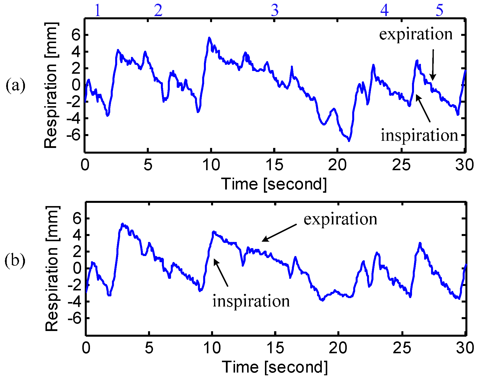
3]. For example, “speech” is featured by shorter inspiration and longer expiration [
2], and “fear” presents a shallow and rapid respiration pattern [
3]. According to the National Center for Voice and Speech, improved breath control is not only essential to good singing, but also beneficial to the refinement of speech skills for those who frequently use their voice, e.g., lawyers and sales personnel. It is necessary to develop breathing skills to use the support from diaphragmatic or abdominal muscle for optimal singing/speech performance [
4]. Chest breathing is human’s natural response to emergencies. When people feel stressed or anxious, they tend to increase the breathing rate and shift from diaphragmatic breathing to chest breathing, in order to take in extra oxygen to defend themselves [
5]. However, chest breathing breaks the natural balance between oxygen and carbon dioxide in the body, which may lead to a variety of health problems such as musculoskeletal disorders [
5]. In the modern, fast-paced society, more and more people are facing stress problem in both work and life. Diaphragmatic breathing is considered as a healthier way of breathing, which is marked by the abdominal expansion rather than the chest rib cage expansion [
6]. It is a popular relaxation technique that helps stressed people to calm down.
To monitor the physical/emotional states of patients, assure the validity of breath control, and evaluate the efficacy of diaphragmatic breathing, it calls for accurate assessment of respiratory patterns at both chest and abdomen. The conventional respiration measurement techniques are mostly contact means, e.g., air mattress [
7], the electrocardiogram (ECG) monitor [
8], and the wearable systems [
9], which bring discomfort to the patients and insufficient accuracy in respiration measurement. Moreover, the contact means may cause the subjects to breathe abnormally, while the spontaneous breathing is usually required for accurate assessment. Doppler radar technologies have been used for various applications, such as localization and mapping [
10] and automotive obstacle detection [
11]. Considering the disadvantages of the existing respiration assessment techniques, Doppler radar serves as a good alternative. Doppler radar provides a noncontact and more accurate approach to assess the respiration motion because it measures the whole chest wall or abdomen [
12,
13,
14,
15]. However, due to the high pass characteristic of the AC coupled baseband structure, the conventional alternating current (AC) coupled radar sensor is subject to signal distortion in measuring respiration, which has a short period of stationary moments after expiration in the respiration cycle [
12]. To solve this problem, direct current (DC) coupled radar sensors have been proposed by researchers for accurate respiration measurement without signal distortions [
16,
17]. In the adaptive DC coupled radar sensor recently proposed by the authors [
16,
18], the baseband amplifier is not biased at a fixed point, but adaptively tuned through an external DC power source. In this way, the radar sensor is always able to measure respiration motion with sufficient high gain. Since the DC coupled baseband has “all-pass” architecture, it is possible for the radar sensor to accurately measure the complete respiration patterns without losing any signal information, which is a benefit to accurate assessment.
In this paper, a multi-radar system using two 2.4 GHz DC coupled radar sensors have been proposed for noncontact assessment of the respiration patterns at both chest and abdomen. The two radar sensors employ the same patch antennas but with different polarizations, in order to minimize the interference from each other. It is also feasible to use just one radar sensor with beam-scanning capability to simultaneously measure the breathing motions at multiple body locations [
19]. The DC coupled radar system allows simultaneous assessment of the respiration motions at chest and abdomen with a very high accuracy.
Experiments were conducted in the lab environment to validate the proposed technique of using multi-radar system for noncontact assessment of different respiration patterns. Before the experiments, the subject person was trained to generate the diaphragmatic breathing and chest breathing. During the experiment, the subject laid on a bed in the supine position, with the two radar sensors facing his/her chest and abdomen, respectively. Different breathing patterns were collected and evaluated when the subject was asked to perform natural breathing, diaphragmatic breathing and chest breathing. The respiration assessment was also carried out for a group of people with different genders and physical characteristics. They were asked to perform natural breathing as well as breathing motions related to physical states of breath holding, cough and speaking. They were also asked to generate respiration patterns for the emotional states of anger and tenderness.
2. Radar Sensor System
Doppler radar provides a noncontact and noninvasive approach for physiological monitoring. It is especially suitable for some scenarios where contact means are prohibitive, such as burned patients. The radar noncontact approach potentially ensures more accurate assessment, because the target subject tends to have more spontaneous breathing patterns when they are not aware of the measurement device. Additionally, the contact measurement techniques may affect the spontaneous way of breathing by introducing discomfort. In radar respiration measurement, a single-tone carrier signal is transmitted to the subject’s chest or abdomen. The reflected signal from chest or abdomen is phase-modulated by the breathing motion. In this paper, the radar sensor was designed with quadrature architecture. So the measured signals at the baseband outputs are
where θ is a constant phase offset determined by the initial position of the subject,
x(
t) is the breathing motion, Δϕ(
t) is the residual noise including phase noise and other noise sources,
AI/
AQ are the amplitudes and
DCI/
DCQ are the DC offsets of the
I/
Q channels, respectively.
Several demodulation techniques, such as linear demodulation and arctangent demodulation, can be used to recover the breathing motion from the radar-received signal [
20,
21]. However, linear demodulation is not suitable for accurate respiration volume assessment because this technique is inherently based on small angle approximation, which does not provide efficient displacement accuracy [
11]. Arctangent demodulation is accurate in displacement measurement and robust against the null point problem in radar respiration sensing [
17,
22]. However, it suffers from lack of accuracy if the radar sensor is AC coupled at baseband, since AC coupling makes it very difficult for accurate DC calibration due to the signal distortion.
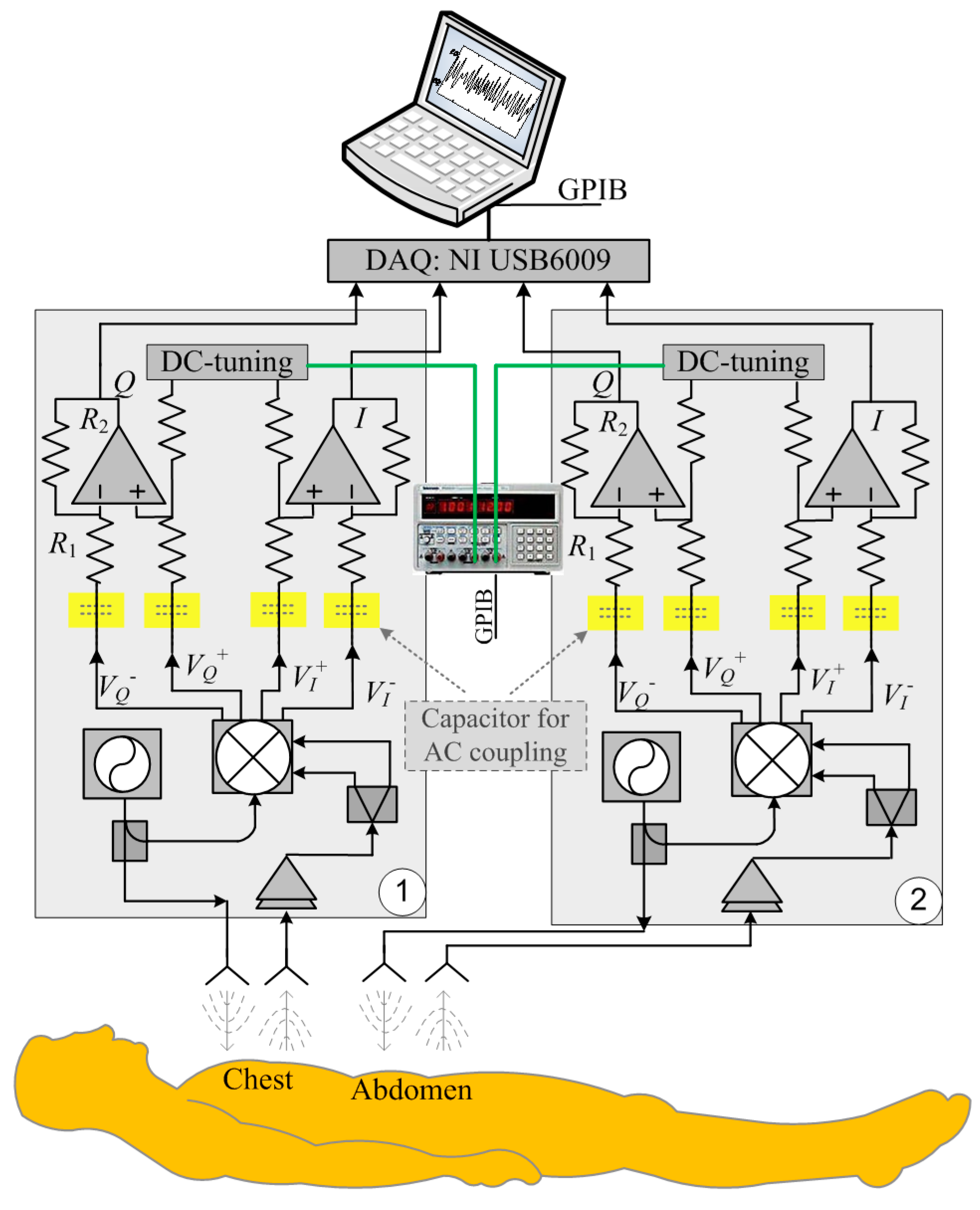
Figure 1 illustrates the block diagram of the DC coupled multi-radar system that consists of two identical DC coupled radar sensors for measuring the respiration patterns at chest and abdomen. The DC coupled radars are configured with the fine-tuning adaptive feedback loop, which can dynamically adjust the DC offset to make sure the baseband circuitry can provide sufficient high gain as well as the optimal dynamic range [
18]. The radar baseband
I/
Q outputs are captured by the data acquisition card (NI USB6009), which is connected to a laptop. The laptop also controls the power supply to perform adaptive DC tuning via a GPIB cable. The transmit power is 0 dBm, which is more than 20 dB lower than the Federal Communications Commission (FCC) regulations on transmit power in the 2.4 GHz ISM band [
23]. The voltage-controlled oscillator (VCO) used in the system is from from Hittite Microwave and was designed for commercial applications and the spectrum fits within the ISM band from 2.40 GHz to 2.84 GHz.
Figure 1.
Block diagram of the DC coupled multi-radar system for respiration assessment at chest and abdomen.
Figure 1.
Block diagram of the DC coupled multi-radar system for respiration assessment at chest and abdomen.
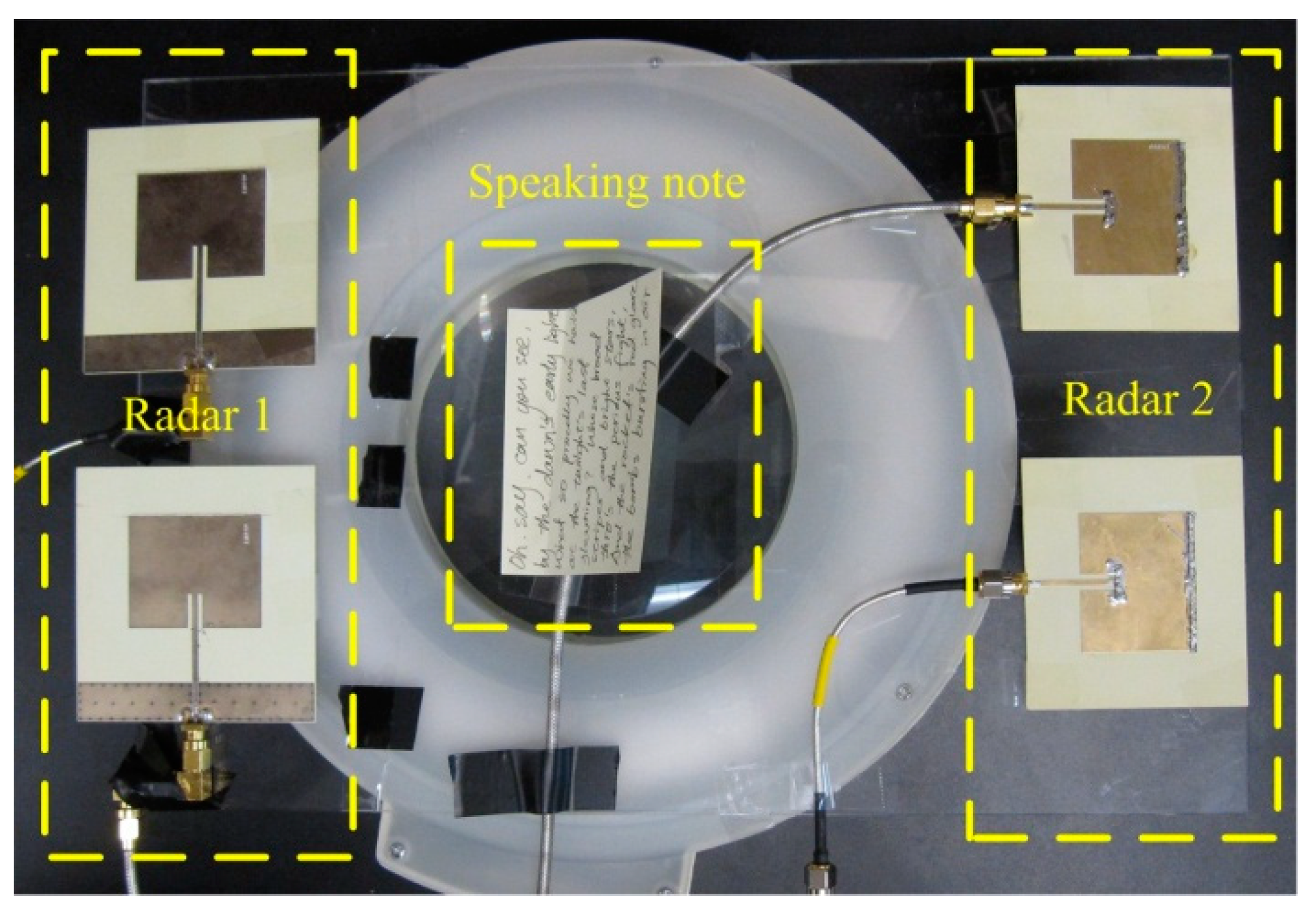
Four patch antennas were used, since each radar sensor needs one antenna for transmitting and one antenna for receiving, respectively. Patch antenna was chosen for the following reasons: (1) it has a directional radiation pattern and reduce interferences from the back of the radar sensor; (2) it has a low cost, low profile, and is easy to fabricate; and (3) the planar patch antenna can potentially be integrated with the radar circuitry on the same printed circuit board. For each subject, the antennas’ positions were adjusted so that one radar radiates signals to the chest and the other radar radiates signals to the abdomen. The antennas were also placed in such a way that one radar sensor was horizontally polarized and the other one was vertically polarized, as shown in
Figure 2. The two sensors have little interference to each other, due to the following reasons: (1) The two sensors use two free-running VCOs. Therefore, the carrier frequencies of the two sensors are slightly different. At 2.4 GHz carrier, the difference could easily be in the order of MHz. (2) The difference in carrier frequencies would be down-converted to the baseband. The sensor baseband was designed using operational amplifiers to have very narrow bandwidth of less than 1 MHz. Therefore, the interference could be easily rejected by the baseband circuitry. (3) Our radar operation is strongly based on coherent detection that effectively eliminates the impact of phase noise of each VCO on its corresponding receiver, while the two radar sensors are non-coherent and can hardly cause any significant impact on each other. (4) The different polarization of antennas further reduces the interference signal that leaks from one sensor to the other.
Figure 2.
The antennas were placed in such a way that one radar used horizontally polarized antennas and the other radar used vertically polarized antennas. The speaking note was used to guide the subject during reading measurement.
Figure 2.
The antennas were placed in such a way that one radar used horizontally polarized antennas and the other radar used vertically polarized antennas. The speaking note was used to guide the subject during reading measurement.
The above assumptions were experimentally verified by turning one of the sensors on and off. Little difference was observed on the signal detected by the other sensor. There might be occasional scenarios (approximately once in 5 min) where a strong spike/spur occurs at baseband output for a very short time interval. However, due to the free-running nature of the VCOs being used, the carrier frequencies tend to differ and therefore the spike/spur would disappear right away and can be eliminated in digital signal processing. The noise floor of the radar receiver plays an important role in determining the sensitivity. The factors contributing to the noise floor in CW radar sensor systems may include: (1) flicker noise—which dominates at very low frequencies; (2) white noise—which becomes the main noise source at frequencies higher than the flicker noise corner; (3) sampling rate
fs of the baseband ADC—the amplified white noise is folded into the frequency band from dc to
fs due to aliasing; and (4) the resolution bandwidth (
RBW), which is determined by the time-domain window size of the Fourier transform—the narrower the
RBW, the less noise energy is contained in a single point of the periodogram [
24]. According to the analysis in [
24], the input-referred noise floor can be quantified as:
where
Fwhite is the noise figure at frequencies above the flicker noise corner frequency,
Fflicker is the noise figure contributed by flicker noise,
B is the equivalent noise bandwidth of the receiver, and
RBW = 1/
TW is the resolution bandwidth of the periodogram, which is determined by the Fourier transform window size
TW. In the radar system being used in this paper, a typical window size of 10~20 s was used for real-time radar respiration sensing application. Assuming
Fflicker = 40 dB at 1 Hz,
Fwhite = 7 dB,
B = 1 MHz,
RBW = 0.1 Hz, and
fs = 20 Hz, the input-referred noise floor is:
It should be noted that the relative strength of flicker noise and white noise is controlled by several parameters, such as fs and B. If a high sampling rate, e.g., 10 kHz, was used, the input-referred white noise will be reduced to −157 dBm, making the flicker noise dominate the noise floor in the receiver chain.
3. Experiments
Experimental evaluation was carried out in the lab environment for a group of ten healthy subjects including four females and six males. The anthropometric data of the study subjects are shown in
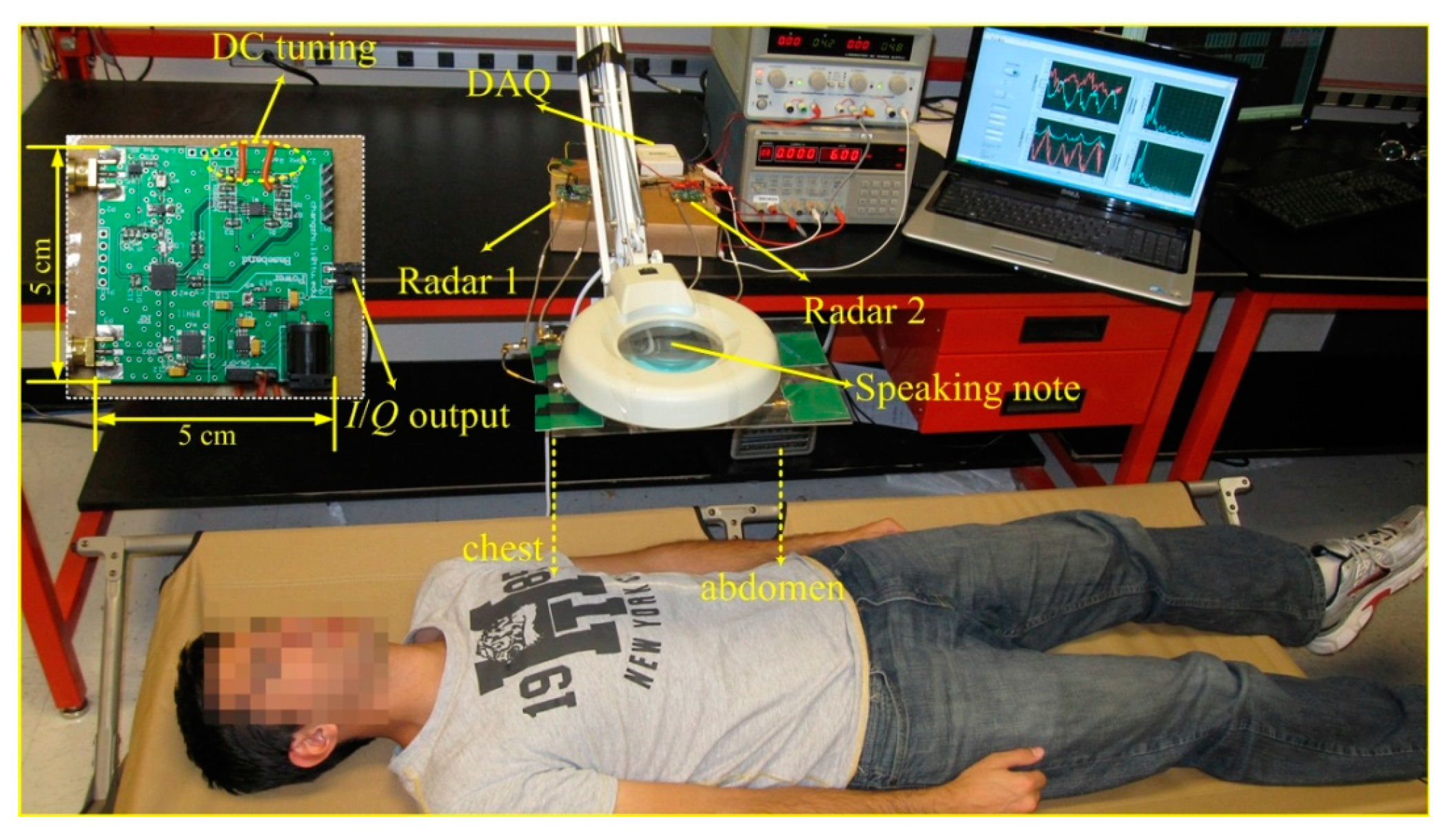
Table 1. One of the subjects was trained to generate chest breathing and diaphragmatic breathing. And the remaining subjects were volunteers that were not trained in respiratory exercise. The experimental setup is shown in
Figure 3. The subject lied in a folding bed in the supine position, with a distance of 50 cm from the patch antennas, as shown in
Figure 3. The two radar sensors were placed on the table, connecting the antennas via coaxial RF cables. The data acquisition card (NI USB6009) collected the radar-measured signals, which were processed and displayed in real time by a LabVIEW program running on a laptop. Two power supplies were used to provide four channels of DC voltage to adaptively tune the DC offset for the two radar sensors. It should be noted that the DC tuning process should be carried out for every subject and every experiment. The DC offset was caused by the reflections from the stationary part of the subject body and the stationary objects around the subject. Each subject person has a different physical characteristics and each experiment has different surrounding environment, which leads to different DC offsets. In the newly developed radar sensor system, the function of automatic DC offset tuning has been integrated in the microcontroller in the baseband circuitry. That way, the system would automatically tune the DC offsets to adapt to different subjects.
Three experiments were conducted in this paper. They are described as follows.
Figure 3.
The Experimental setup of the DC coupled multi-radar system for assessment of different respiration patterns at chest and abdomen. Inset shows the photograph of the designed miniature DC coupled radar sensor.
Figure 3.
The Experimental setup of the DC coupled multi-radar system for assessment of different respiration patterns at chest and abdomen. Inset shows the photograph of the designed miniature DC coupled radar sensor.
Table 1.
Anthropometric data of the study subjects.
Table 1.
Anthropometric data of the study subjects.
| Subject | Age | Sex | Chest Circumference | Abdominal Circumference |
|---|
| S1 | 26 | Female | 84 cm | 72 cm |
| S2 | 30 | Female | 88 cm | 73 cm |
| S3 | 25 | Female | 76 cm | 64 cm |
| S4 | 23 | Female | 80 cm | 67 cm |
| S5 | 27 | Male | 105 cm | 91 cm |
| S6 | 26 | Male | 99 cm | 89 cm |
| S7 | 22 | Male | 93 cm | 85 cm |
| S8 | 27 | Male | 107 cm | 93 cm |
| S9 | 31 | Male | 112 cm | 90 cm |
| S10 | 22 | Male | 103 cm | 90 cm |
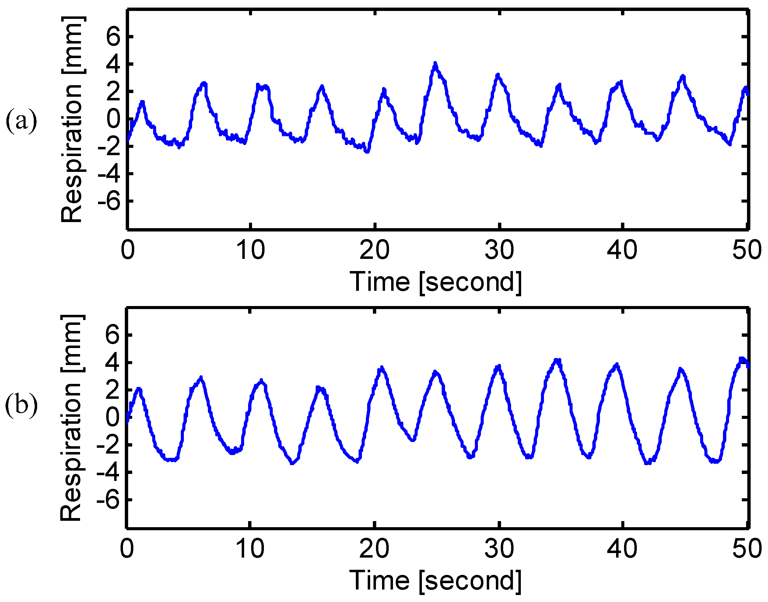
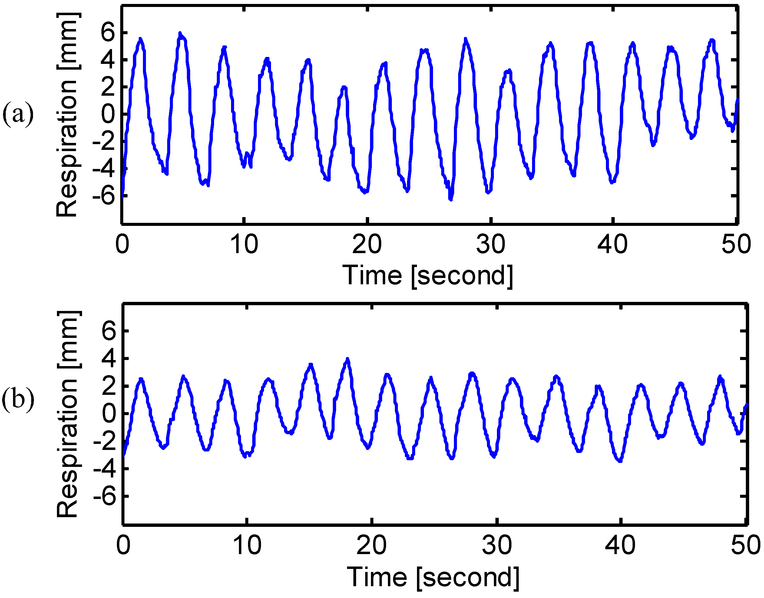
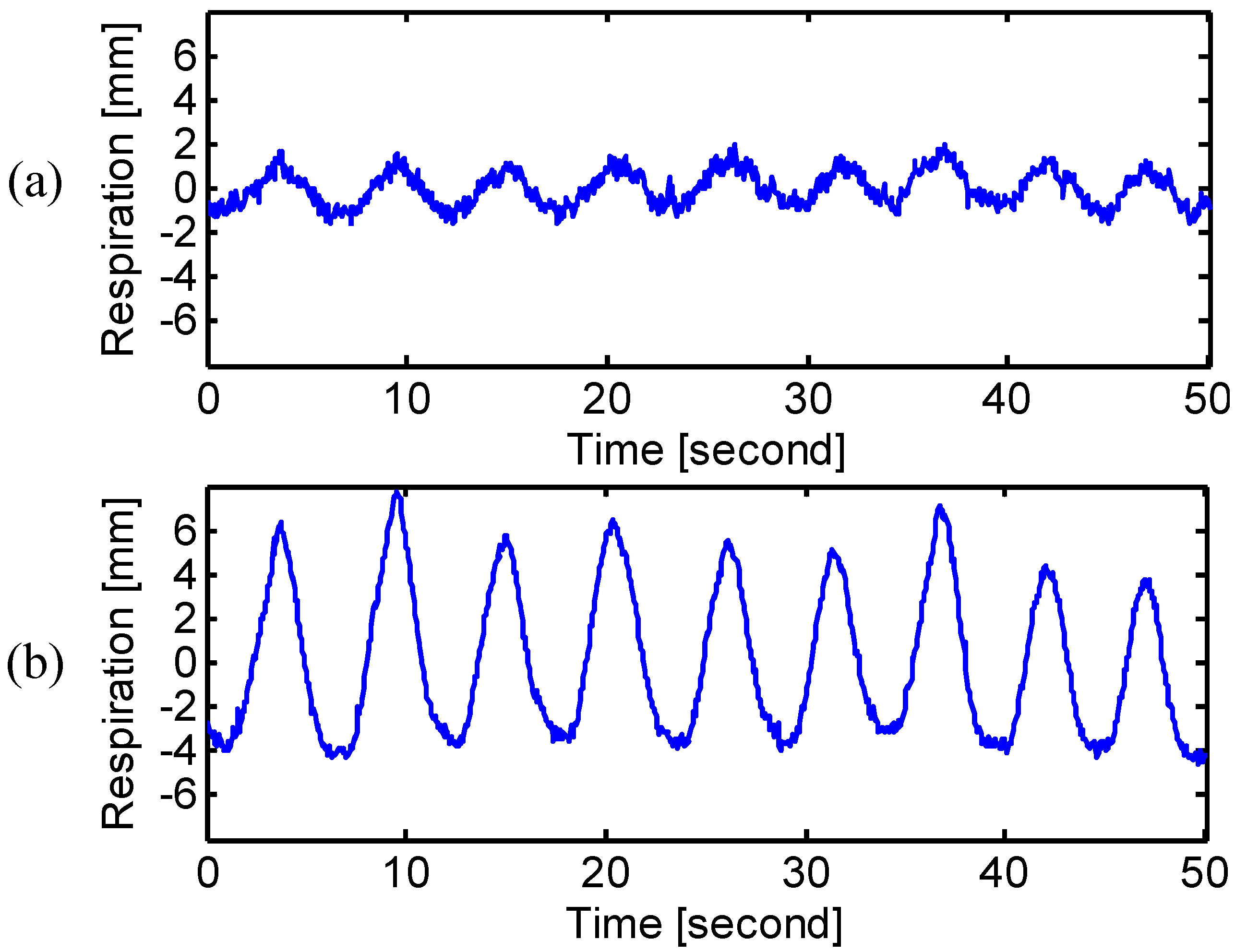
3.1. Breathing Type Discrimination
First, the different breathing types of natural breathing, chest breathing and diaphragmatic breathing were assessed. Only one subject participated in this experiment, as it would take a significant amount of time and effort for a normal subject to develop the desired breathing types by following the respiratory exercise [
22,
25]. It was difficult to train all the subjects that volunteered to participate in the experiment. To develop the diaphragmatic breathing, the subject was trained by putting one hand on the chest and one hand on the abdomen, and, with the help of hands to feel the chest and abdomen movement, the subject actively reduced the chest motion but breathed slowly through the abdomen [
26]. After one week of exercise, the subject was able to breathe diaphragmatically without hands placed on the body. When people feel stressed or anxious, they tend to develop chest breathing by increasing the breathing rate and depth through the rib cage expansion [
27]. The subject was asked to think of his stressed experience and mimicked the way he took breath during the stressed moment.
3.2. Physical Breathing Patterns
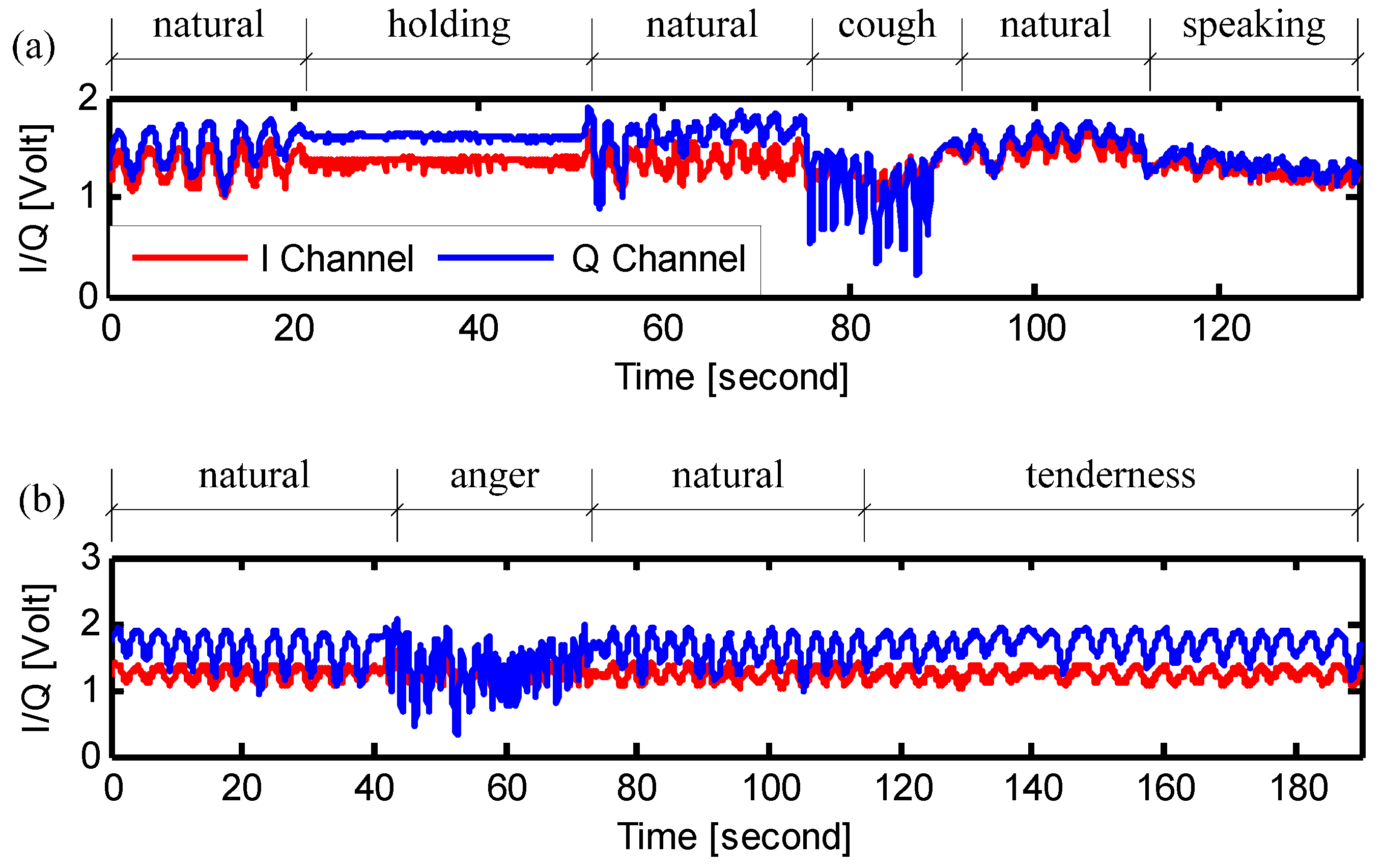
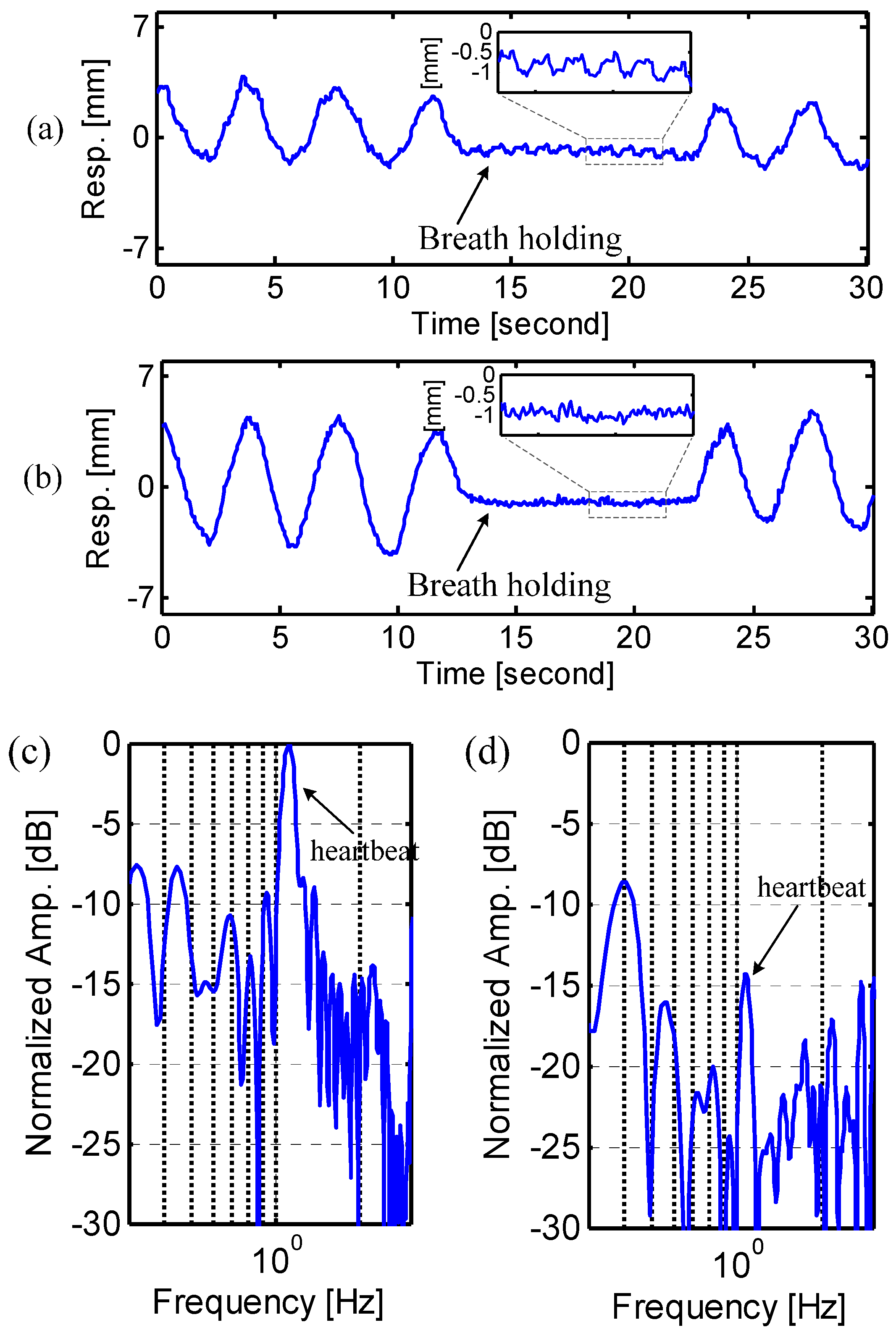
In the second experiment, the physical breathing patterns of the ten subjects were assessed. The procedure of the experiment is shown in
Figure 4a. First, the subjects breathed normally at his/her natural rhythm. Then the subject was asked to hold the breathing as long as possible. After breath holding, the subjects started to breathe naturally again. The breath holding experiment is helpful in assessment of the radar performance in monitoring obstructive sleep apnea syndrome [
27,
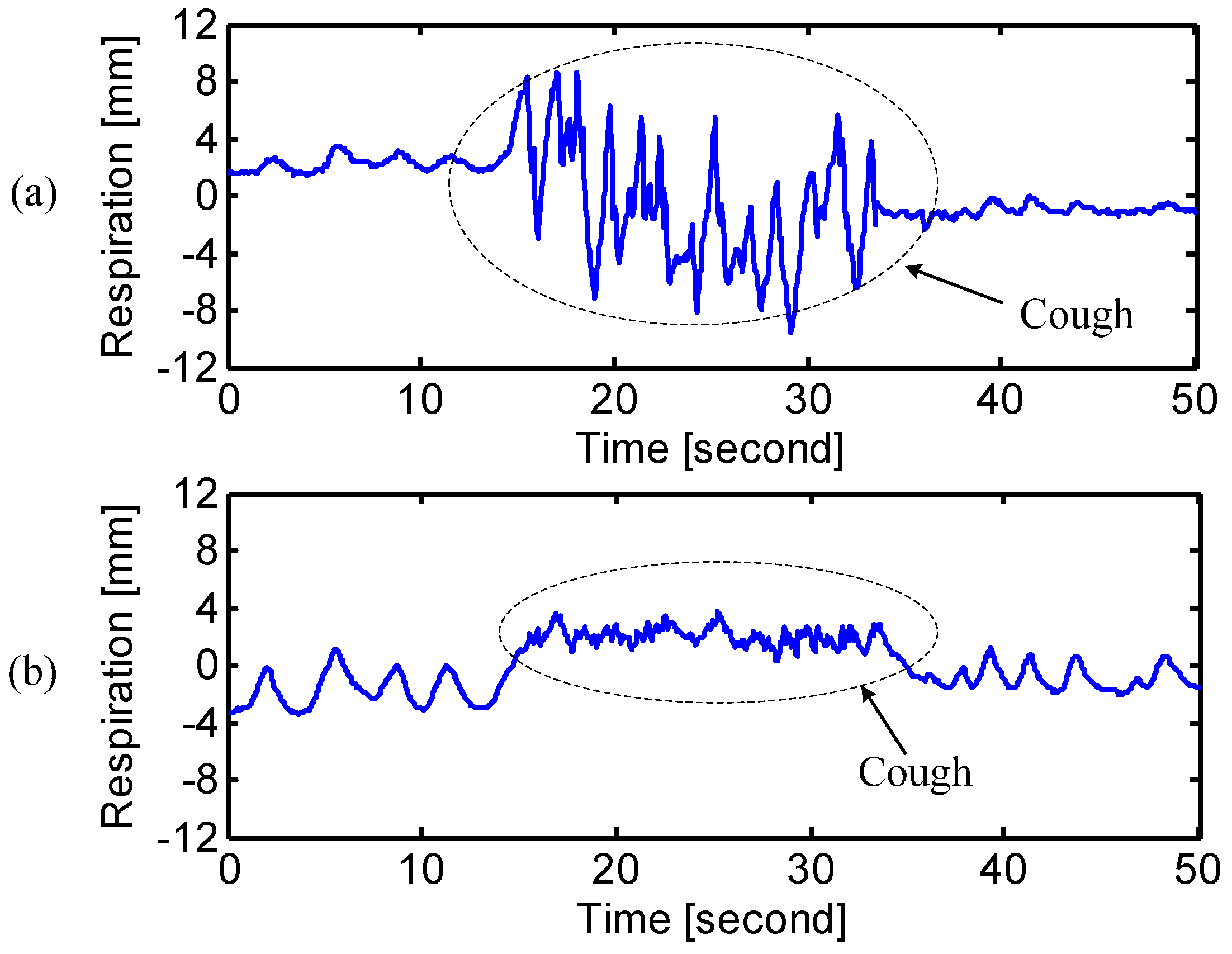
28]. The subject was also asked to cough for a short period. This was to simulate the situations of how the breathing pattern may vary when the subject is sick. Finally, the subjects read the speaking note, which is the lyrics of the US national anthem, as shown in
Figure 2 and
Figure 3. This was to simulate the assessment of the respiration patterns in breath control exercise that is beneficial to improve speech and singing [
2,
4].
Figure 4.
Signals measured at the abdomen of the subject showing the experimental procedures of (a) the assessment of physical breathing patterns; and (b) the assessment of emotional breathing patterns.
Figure 4.
Signals measured at the abdomen of the subject showing the experimental procedures of (a) the assessment of physical breathing patterns; and (b) the assessment of emotional breathing patterns.
3.3. Emotional Breathing Patterns
In the third experiment, the emotional breathing patterns of the subjects were measured. It has been proven that the breathing patterns change in response to the emotional states, such as anger, anxiety, tenderness, sadness,
etc. [
3]. In other words, the breathing pattern is strictly related to the emotional state. It would be very interesting if we can tell the emotional state of a subject by remotely assessing his breathing patterns. This paper illustrates the preliminary results that show the feasibility of accurately measuring different respiration patterns via Doppler radar sensing, while more rigorous evaluation of the emotional states needs further research and experimental efforts by introducing spontaneously produced emotions.
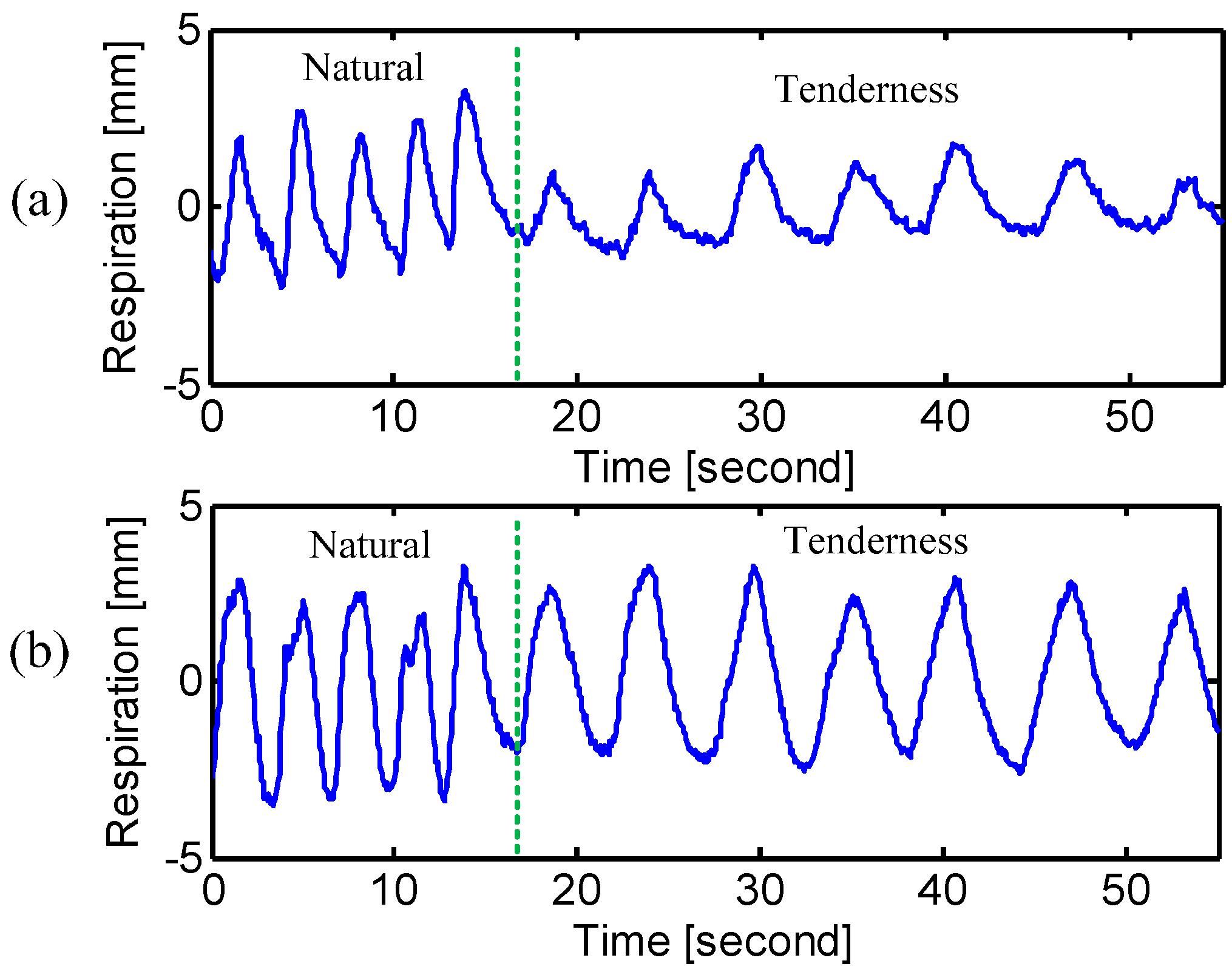
The procedure of the experiment is shown in
Figure 4b. The subjects started from the natural breathing and then were asked to reproduce two emotional sates of “anger” and “tenderness”. The state of “anger” was reproduced by giving the following breathing indications to the subjects: “breathe sharply through the nose; focus the eyes; tense the body as if you are ready to attack…” [
1]. The subjects were then restored to natural breathing after the “anger” state. Finally, the subjects were asked to reproduce the emotional state of “tenderness” by following the indications of “keep body relaxed; put a little smile; breathe very evenly and gently” [
1].


