
Upper Limb Kinematics Using Inertial and Magnetic Sensors: Comparison of Sensor-to-Segment Calibrations

Abstract
:1. Introduction
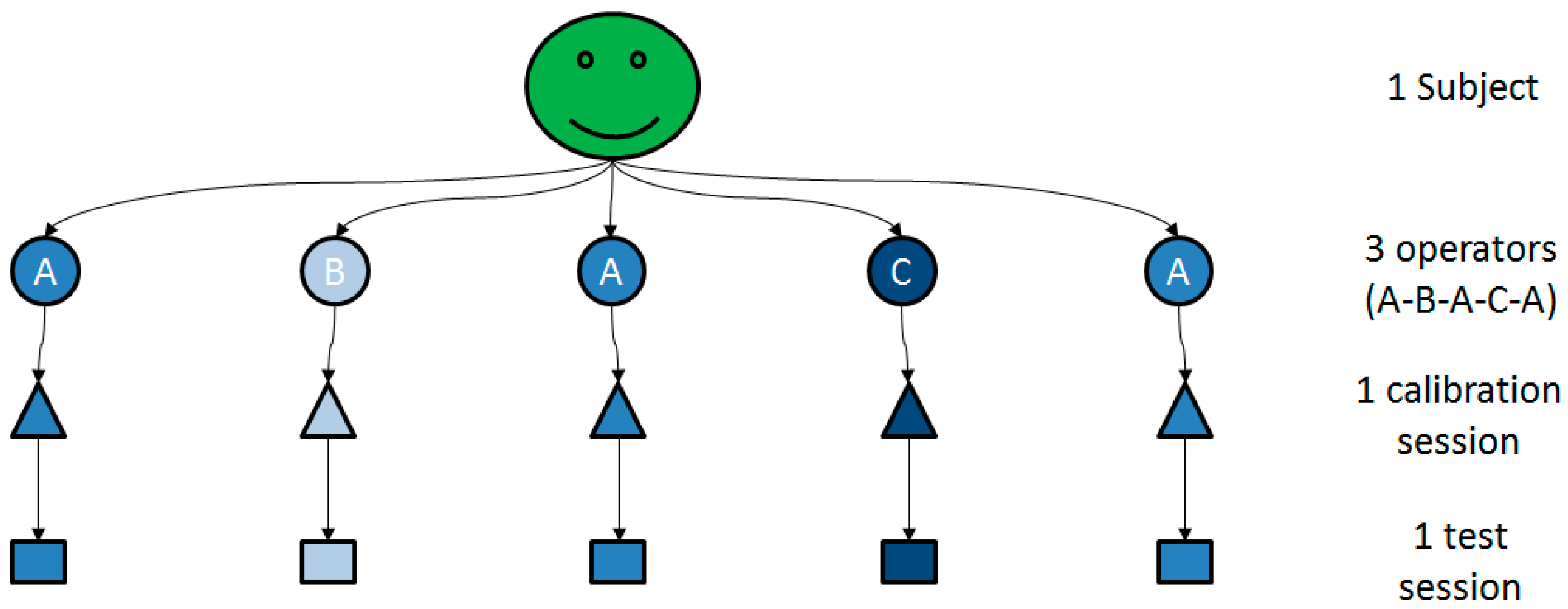
2. Methods
2.1. Participants
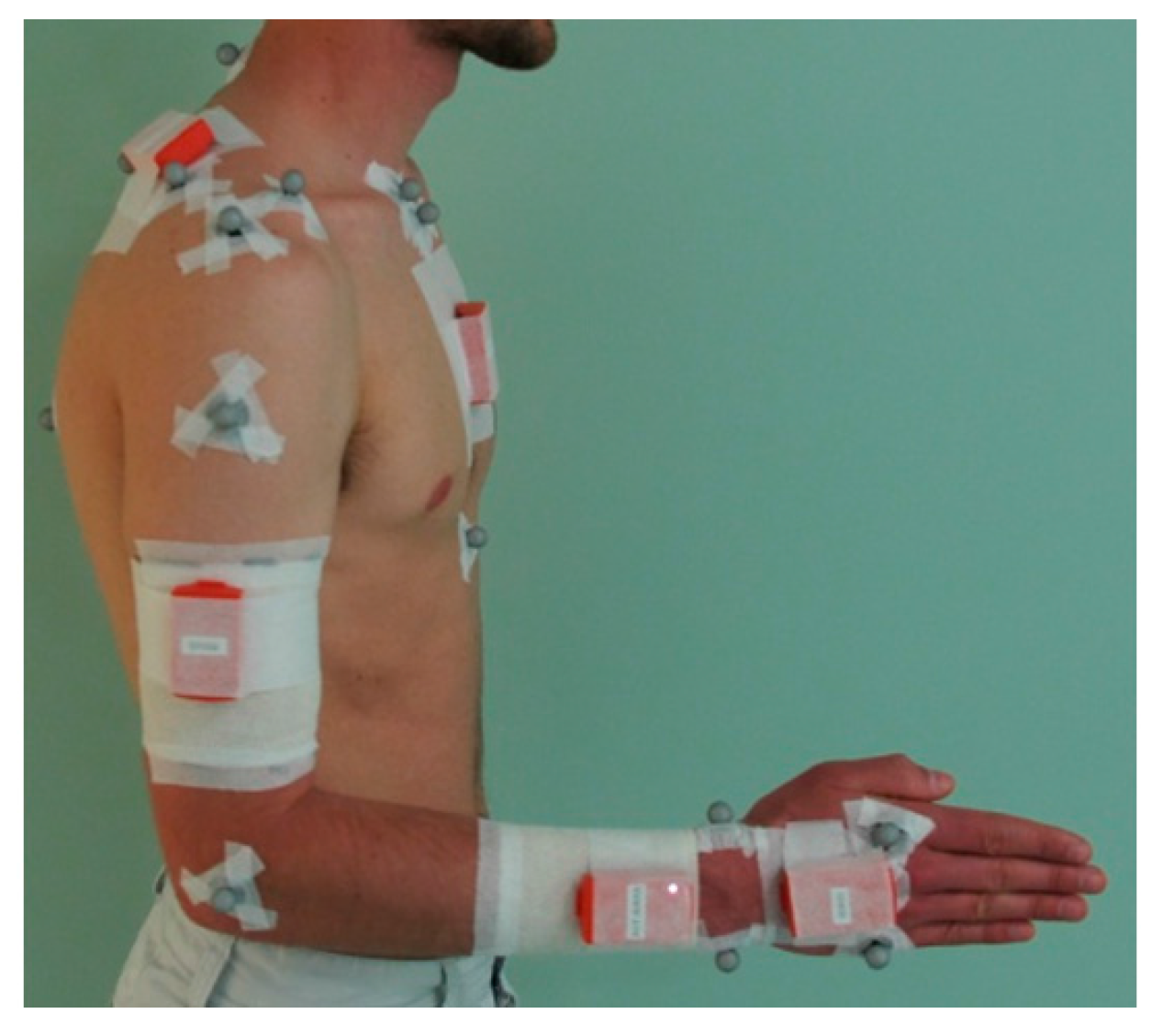
2.2. Technologies Used
2.3. Experimental Protocol


- -
- Pose STATIC_1: upper limbs along the body, in neutral forearm pronation-supination (PS), fingers pointing downwards;
- -
- Pose STATIC_2: upper arm along the body, elbow flexed at 90°, in neutral forearm PS, fingers pointing forward;
- -
- elbFE: starting from STATIC_2, performing right elbow flexion-extensions (FE), with a limited amplitude of [−30°~+30°] around 90°;
- -
- elbPS: starting from STATIC_2, performing right forearm PS, with a complete amplitude, keeping an elbow FE of 90°, hand clenched in a fist.
- -
- handF: maintaining the posture with right forearm and right hand flat on a table;
- -
- wriE: starting from handF, performing right wrist extensions, with a limited amplitude of [0°~30°];
- -
- shoIE: performing right shoulder internal/external rotations (IER), with a limited amplitude of [−10°~+30°], using a handle sliding on a table.
- -
- wriFEmax: starting from STATIC_2, performing maximal wrist flexion-extensions;
- -
- wriAAmax: starting from STATIC_2, performing maximal wrist abduction-adductions;
- -
- elbFEmax: starting from STATIC_2, performing maximal elbow flexion-extensions;
- -
- shoFmax: starting from STATIC_1, performing maximal shoulder flexions;
- -
- shoAmax: starting from STATIC_1, performing maximal shoulder abductions in the scapular plane;
- -
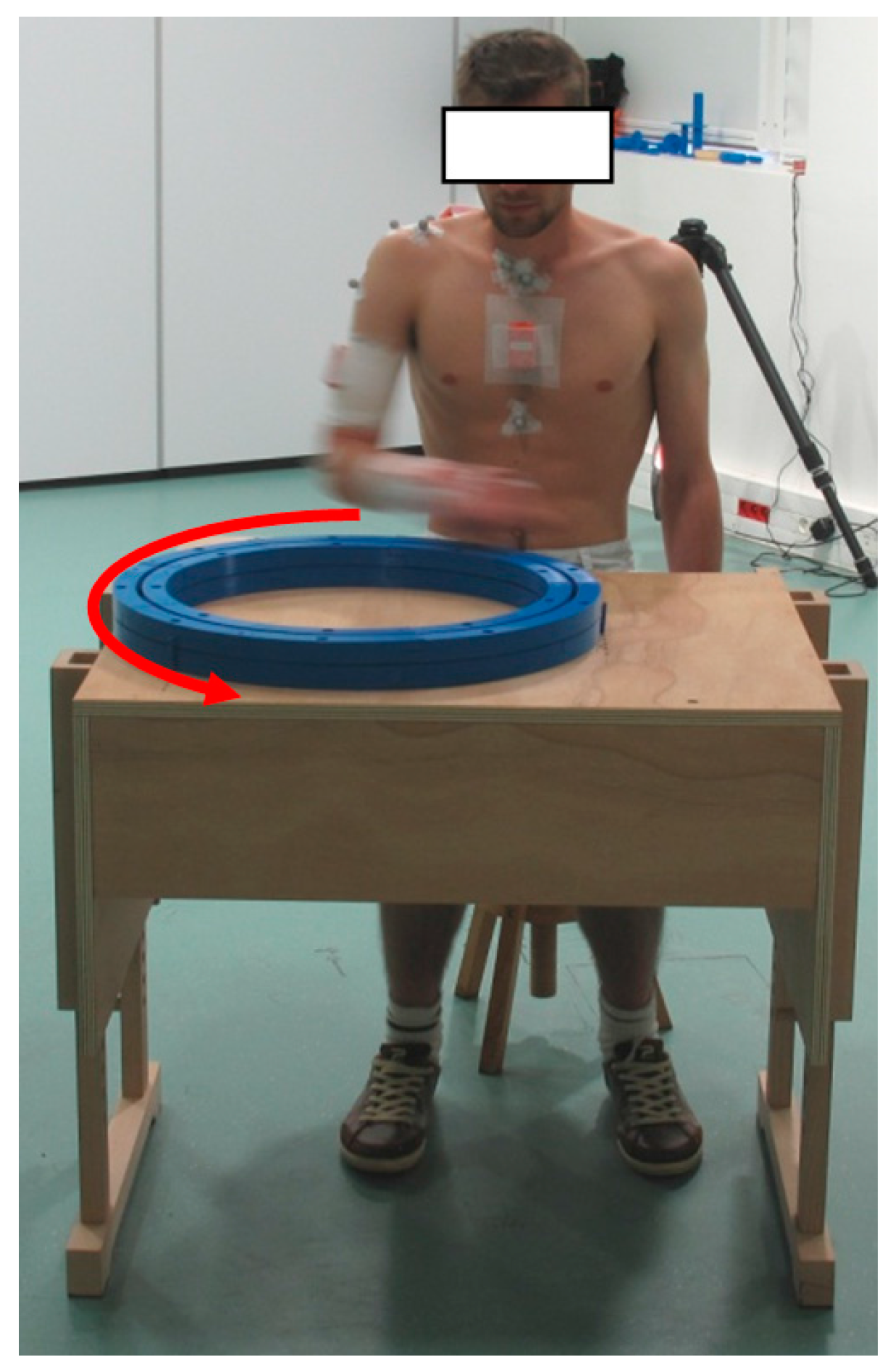
- wheel: seating, performing rotations using a circular wheel placed in front of him (Figure 3).

2.4. Modeling
2.4.1. Sensor-to-Segment Calibrations

| WRIST | ELBOW | SHOULDER (Humero-Thoracic) | |
|---|---|---|---|
| TECH | TECH | TECH | TECH |
| STATIC | STATIC_1 | STATIC_1 | STATIC_1 |
| STATIC_2 | STATIC_2 | STATIC_2 | |
| FUNCT | STATIC_1 + wriE | STATIC_1 + elbFE | STATIC_1 + shoIE |
| STATIC_1 + handF | STATIC_1 + elbPS | STATIC_2 + shoIE | |
| STATIC_1 + wriE + handF | STATIC_1 + elbFE + elbPS | ||
| STATIC_2 + wriE | STATIC_2 + elbFE | ||
| STATIC_2 + handF | STATIC_2 + elbPS | ||
| STATIC_2 + wriE + handF | STATIC_2 + elbFE + elbPS |
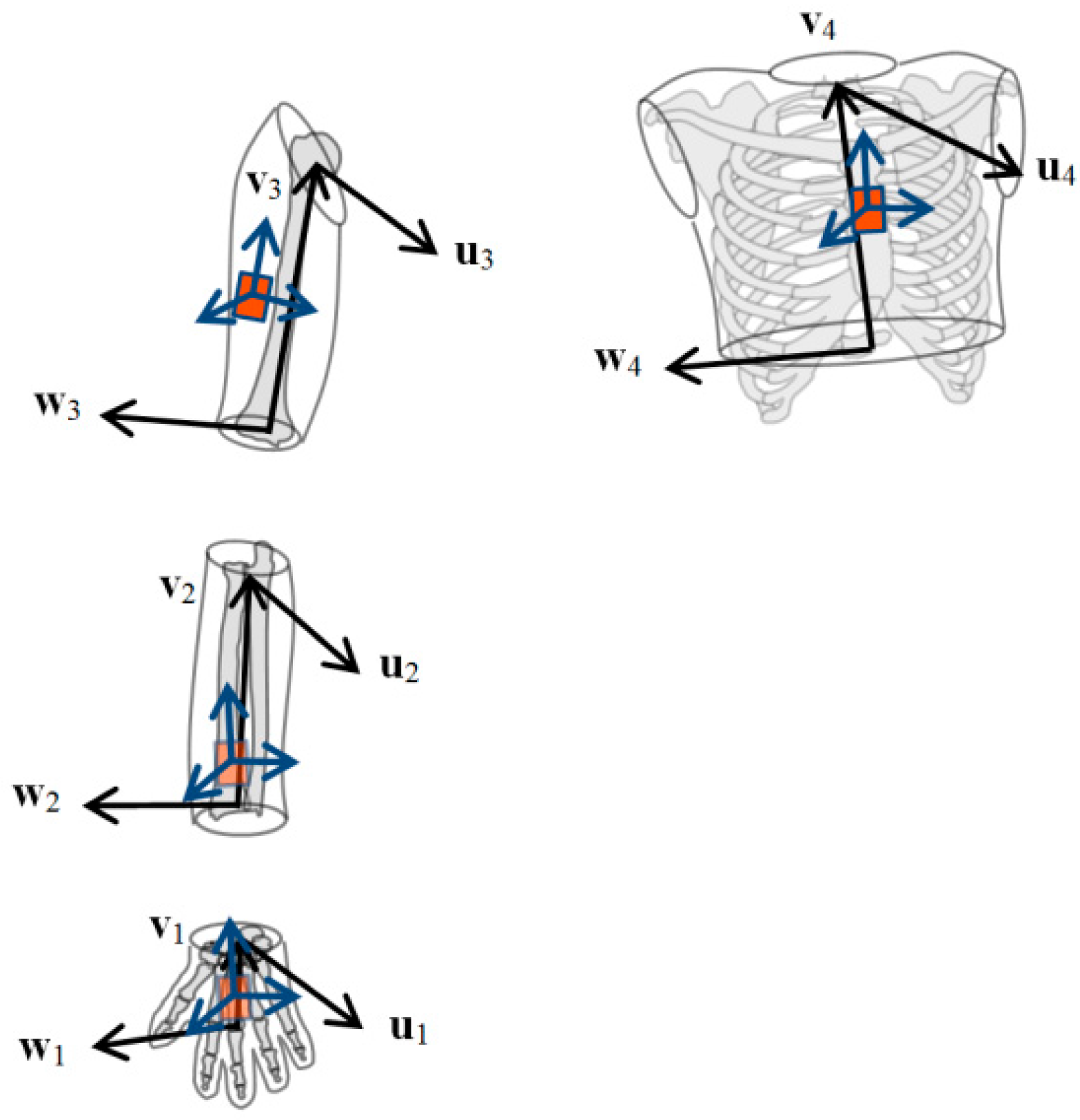
2.4.2. Definition of the Segment Coordinate Systems (SCS)

2.4.3. Definition of the Joint Coordinate Systems (JCS)
2.5. Statistical Analysis
2.5.1. Assessment of Trueness
2.5.2. Assessment of Precision
3. Results
3.1. Wrist
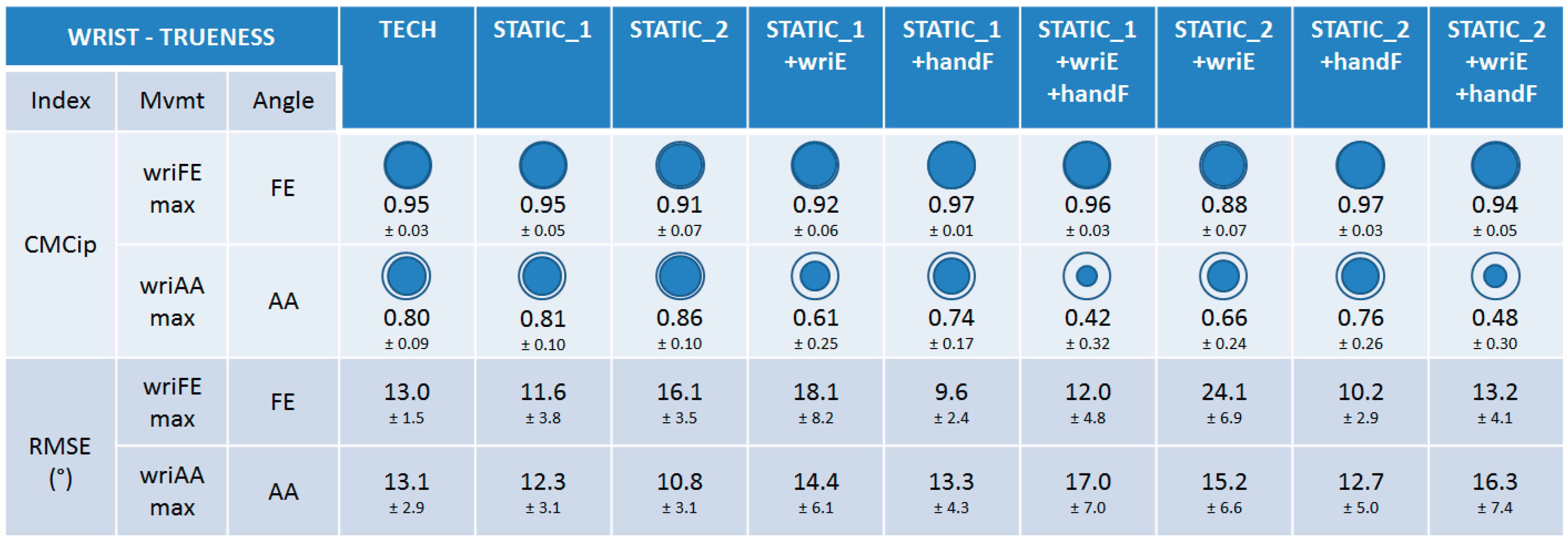
3.1.1. Trueness

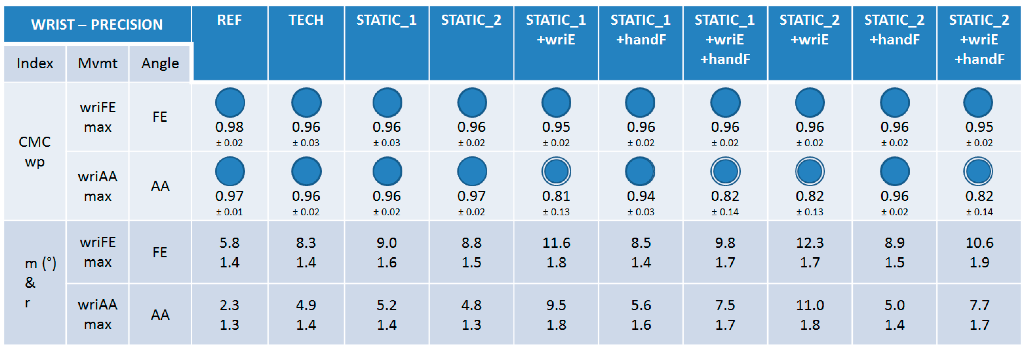
3.1.2. Precision

3.2. Elbow
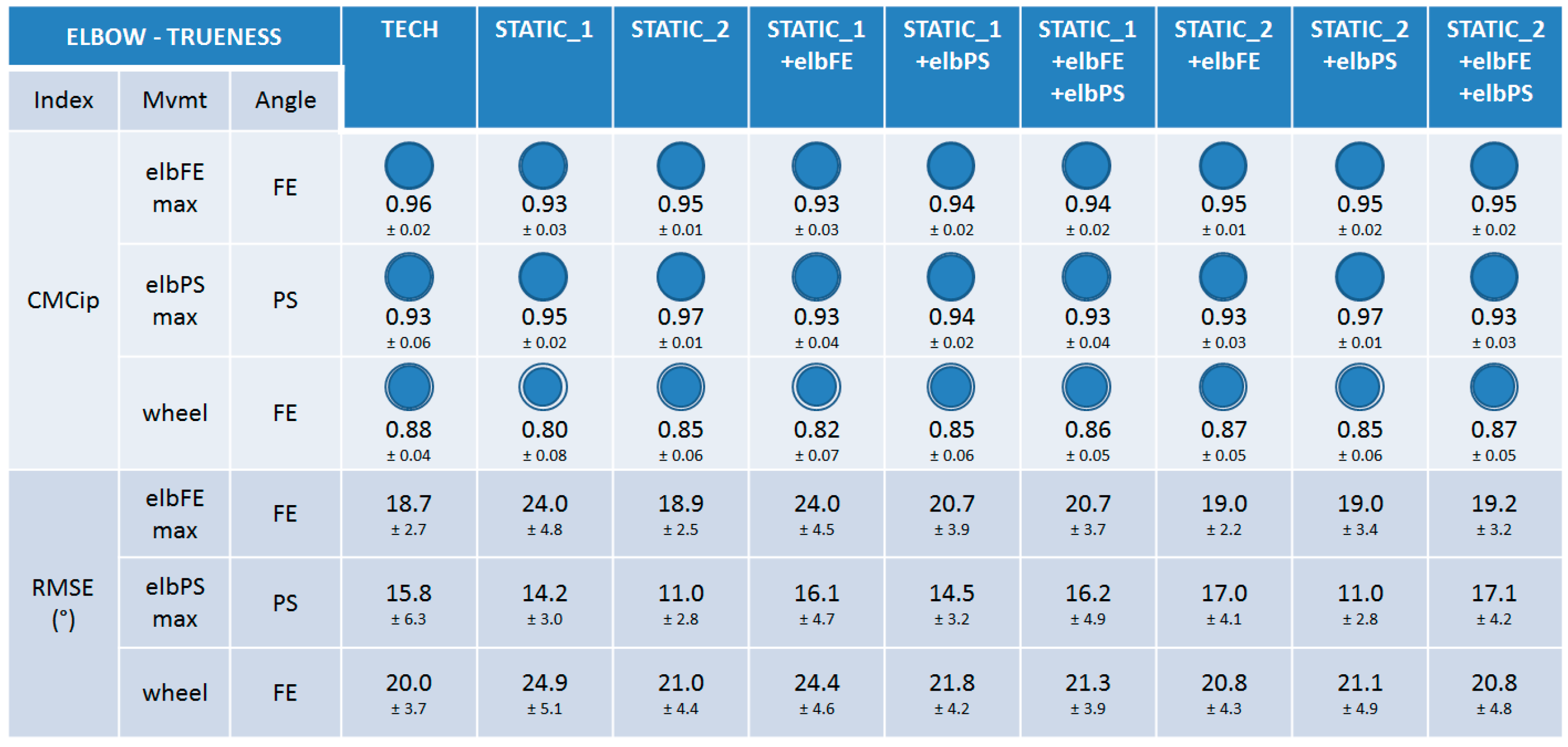
3.2.1. Trueness

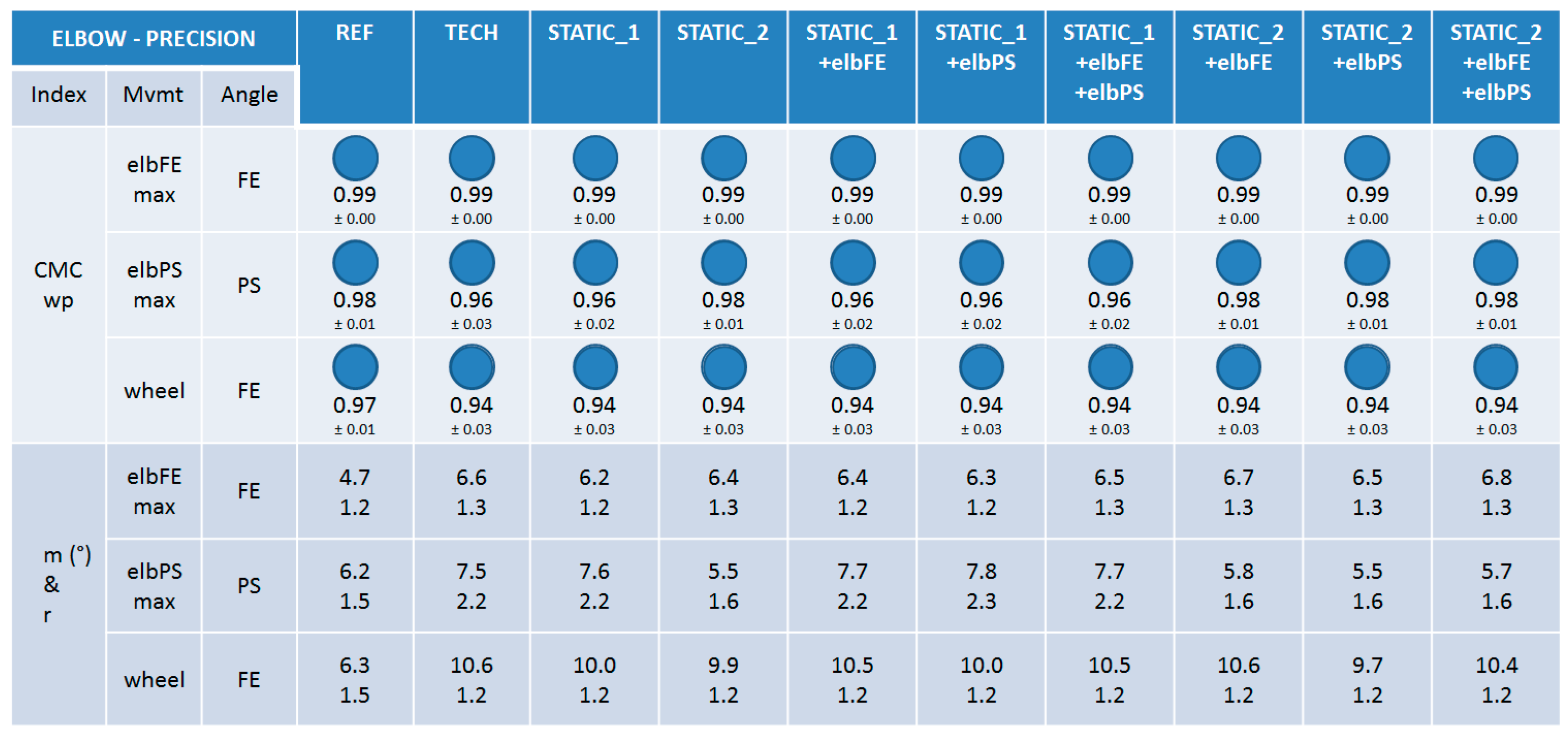
3.2.2. Precision

3.3. Shoulder
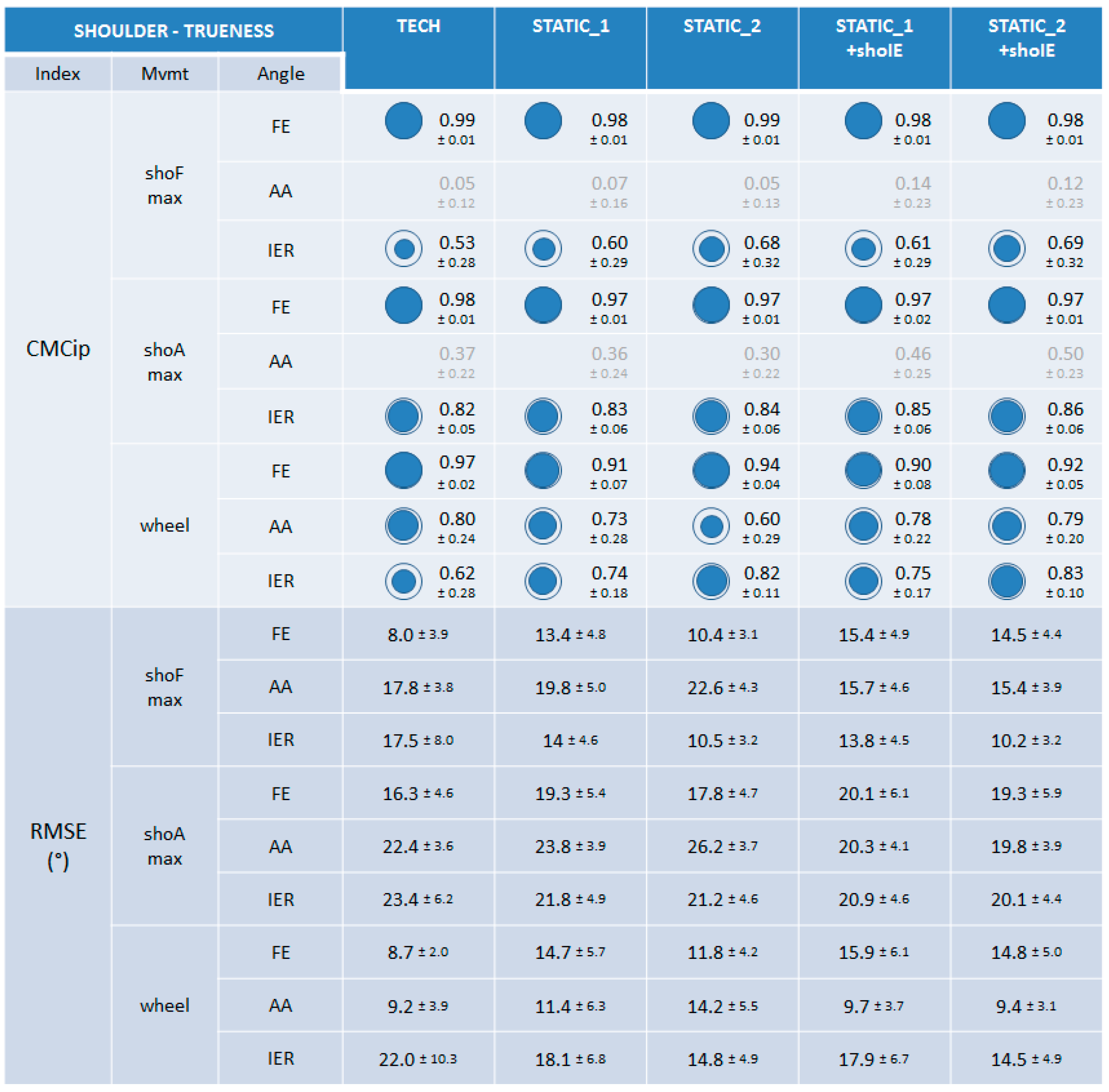
3.3.1. Trueness

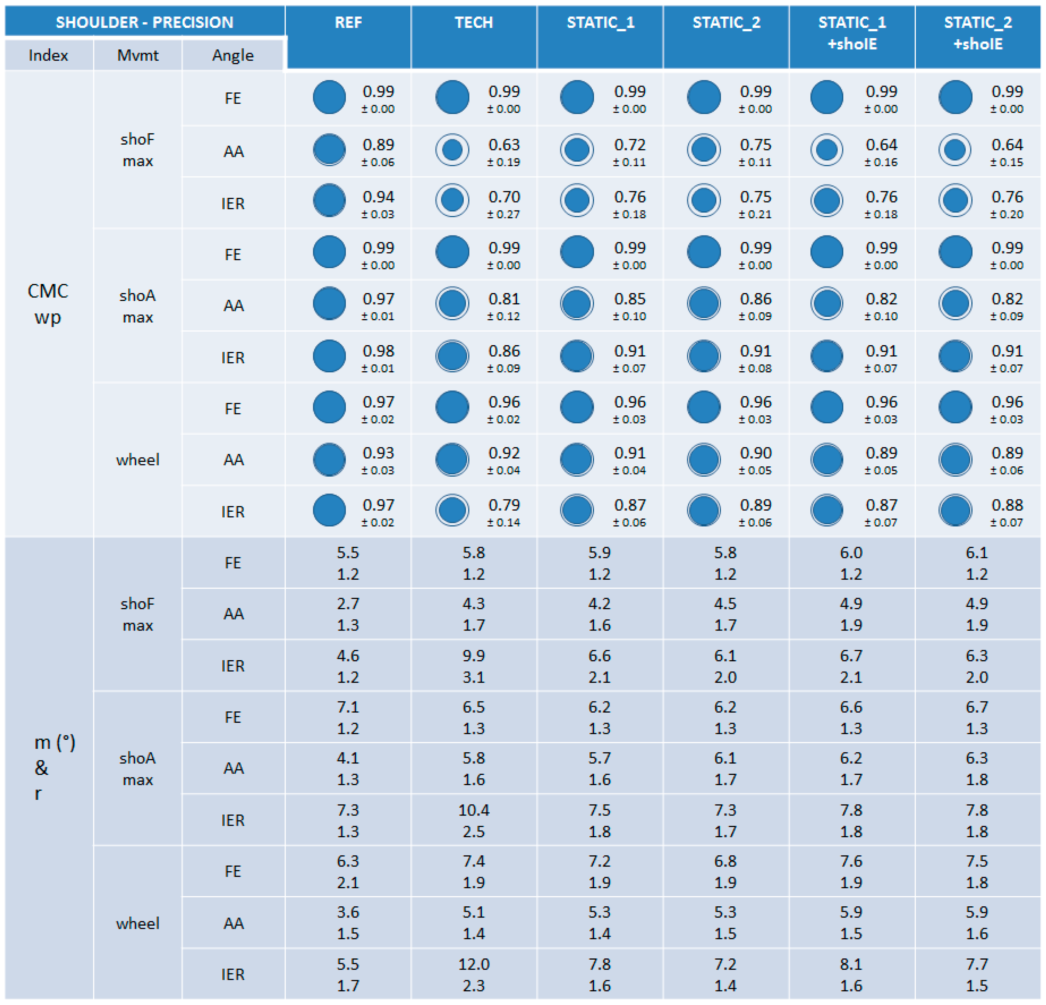
3.3.2. Precision

4. Discussion
4.1. Goal and General Results
4.2. Differences between Calibrations
4.3. Specificities for TECH Calibration
4.4. Comparison with the Literature and Limits of the Study
5. Conclusions and Outlook
Acknowledgments
Author Contributions
Conflicts of Interest
References
- Anglin, C.; Wyss, U.P. Review of Arm Motion Analyses. Proc. Inst. Mech. Eng. H 2000, 214, 541–555. [Google Scholar] [CrossRef] [PubMed]
- Zhou, H.; Hu, H. Human motion tracking for rehabilitation—A survey. Biomed. Signal Process. Control 2008, 3, 1–18. [Google Scholar] [CrossRef]
- Charlton, I.W.; Tate, P.; Smyth, P.; Roren, L. Repeatability of an optimised lower body model. Gait Posture 2004, 20, 213–221. [Google Scholar] [CrossRef] [PubMed]
- Strutzenberger, G. Kinematic and Kinetic Analyses of Human Movement with respect to Health, Injury Prevention and Rehabilitation Aspects. Ph.D Thesis, Fakultät für Geistes-und Sozialwissenschaften, Karlsruhe, Germany, 2011. [Google Scholar]
- Wu, G.; van der Helm, F.C.; Veeger, H.E.; Makhsous, M.; Van Roy, P.; Anglin, C.; Nagels, J.; Karduna, A.R.; McQuade, K.; Wang, X.; et al. Isb recommendation on definitions of joint coordinate systems of various joints for the reporting of human joint motion. Part ii: Shoulder, elbow, wrist and hand. J. Biomech. 2005, 38, 981–992. [Google Scholar] [CrossRef] [PubMed]
- Cappozzo, A.; Catani, F.; Della Croce, U.; Leardini, A. Position and orientation in-space of bones during movement—Anatomical frame definition and determination. Clin. Biomech. 1995, 10, 171–178. [Google Scholar] [CrossRef]
- Coley, B.; Jolles, B.M.; Farron, A.; Bourgeois, A.; Nussbaumer, F.; Pichonnaz, C.; Aminian, K. Outcome evaluation in shoulder surgery using 3D kinematics sensors. Gait Posture 2007, 25, 523–532. [Google Scholar] [CrossRef] [PubMed]
- Cutti, A.G.; Giovanardi, A.; Rocchi, L.; Davalli, A.; Sacchetti, R. Ambulatory measurement of shoulder and elbow kinematics through inertial and magnetic sensors. Med. Bio. Eng. Comput. 2008, 46, 169–178. [Google Scholar] [CrossRef] [PubMed]
- De Vries, W.H.; Veeger, H.E.; Cutti, A.G.; Baten, C.; van der Helm, F.C. Functionally interpretable local coordinate systems for the upper extremity using inertial & magnetic measurement systems. J. Biomech. 2010, 43, 1983–1988. [Google Scholar] [PubMed]
- Galinski, D.; Dehez, B. Evaluation of initialization procedures for estimating upper limb kinematics with marg sensors. In Proceedings of 4th IEEE RAS & EMBS International Conference, Roma, Italy, 24–27 June 2012; pp. 1801–1806.
- Luinge, H.J.; Veltink, P.H.; Baten, C.T. Ambulatory measurement of arm orientation. J. Biomech. 2007, 40, 78–85. [Google Scholar] [CrossRef] [PubMed]
- Perez, R.; Costa, U.; Torrent, M.; Solana, J.; Opisso, E.; Caceres, C.; Tormos, J.M.; Medina, J.; Gomez, E.J. Upper limb portable motion analysis system based on inertial technology for neurorehabilitation purposes. Sensors 2010, 10, 10733–10751. [Google Scholar] [CrossRef] [PubMed] [Green Version]
- Picerno, P.; Cereatti, A.; Cappozzo, A. Joint kinematics estimate using wearable inertial and magnetic sensing modules. Gait Posture 2008, 28, 588–595. [Google Scholar] [CrossRef] [PubMed]
- Plamondon, A.; Delisle, A.; Larue, C.; Brouillette, D.; McFadden, D.; Desjardins, P.; Lariviere, C. Evaluation of a hybrid system for three-dimensional measurement of trunk posture in motion. Appl. Ergon. 2007, 38, 697–712. [Google Scholar] [CrossRef] [PubMed]
- Ricci, L.; Formica, D.; Sparaci, L.; Lasorsa, F.R.; Taffoni, F.; Tamilia, E.; Guglielmelli, E. A new calibration methodology for thorax and upper limbs motion capture in children using magneto and inertial sensors. Sensors 2014, 14, 1057–1072. [Google Scholar] [CrossRef] [PubMed]
- O’Donovan, K.J.; Kamnik, R.; O’Keeffe, D.T.; Lyons, G.M. An inertial and magnetic sensor based technique for joint angle measurement. J. Biomech. 2007, 40, 2604–2611. [Google Scholar] [CrossRef] [PubMed]
- Luinge, H.J.; Veltink, P.H. Measuring orientation of human body segments using miniature gyroscopes and accelerometers. Med. Bio. Eng. Comput. 2005, 43, 273–282. [Google Scholar] [CrossRef]
- Roetenberg, D.; Luinge, H.J.; Baten, C.T.; Veltink, P.H. Compensation of magnetic disturbances improves inertial and magnetic sensing of human body segment orientation. IEEE Trans. Neural. Syst. Rehabil. Eng. 2005, 13, 395–405. [Google Scholar] [CrossRef] [PubMed]
- Schiefer, C.; Ellegast, R.P.; Hermanns, I.; Kraus, T.; Ochsmann, E.; Larue, C.; Plamondon, A. Optimization of inertial sensor-based motion capturing for magnetically distorted field applications. J. Biomech. Eng. 2014, 136, 121008. [Google Scholar] [CrossRef] [PubMed]
- Bachmann, E.R.; McGhee, R.B.; Yun, X.; Zyda, M.J. Inertial and magnetic posture tracking for inserting humans into networked virtual environments. In Proceeding of In ACM Symposium on Virtual Reality Software and Technology (VRST), Banff, AB, Canada, 15–17 November 2001.
- Koning, B.H.; van der Krogt, M.M.; Baten, C.T.; Koopman, B.F. Driving a musculoskeletal model with inertial and magnetic measurement units. Comput. Methods Biomech. Biomed. Eng. 2015, 18, 1003–1013. [Google Scholar] [CrossRef] [PubMed]
- Kalman, R.E. A new approach to linear filtering and prediction problems. J. Basic. Eng. 1960, 82. [Google Scholar] [CrossRef]
- Vignais, N.; Miezal, M.; Bleser, G.; Mura, K.; Gorecky, D.; Marin, F. Innovative system for real-time ergonomic feedback in industrial manufacturing. Appl. Ergon. 2013, 44, 566–574. [Google Scholar] [CrossRef] [PubMed]
- Zhou, H.Y.; Hu, H.S. Reducing drifts in the inertial measurements of wrist and elbow positions. Instrum. Meas. 2010, 59, 575–585. [Google Scholar] [CrossRef]
- Kontaxis, A.; Cutti, A.G.; Johnson, G.R.; Veeger, H.E. A framework for the definition of standardized protocols for measuring upper-extremity kinematics. Clin. Biomech. 2009, 24, 246–253. [Google Scholar] [CrossRef] [PubMed]
- El-Gohary, M.; Holmstrom, L.; Huisinga, J.; King, E.; McNames, J.; Horak, F. Upper limb joint angle tracking with inertial sensors. In Proceedings of Annual International Conference of the Engineering in Medicine and Biology Society, EMBC, IEEE, Boston, MA, USA, 30 August–3 September 2011; pp. 5629–5632.
- Leardini, A.; Chiari, L.; Della Croce, U.; Cappozzo, A. Human movement analysis using stereophotogrammetry. Part 3. Soft tissue artifact assessment and compensation. Gait Posture 2005, 21, 212–225. [Google Scholar] [CrossRef] [PubMed]
- Parel, I.; Cutti, A.G.; Fiumana, G.; Porcellini, G.; Verni, G.; Accardo, A.P. Ambulatory measurement of the scapulohumeral rhythm: Intra- and inter-operator agreement of a protocol based on inertial and magnetic sensors. Gait Posture 2012, 35, 636–640. [Google Scholar] [CrossRef] [PubMed]
- Dumas, R.; Cheze, L.; Verriest, J.P. Adjustments to mcconville And young et al. Body segment inertial parameters. J. Biomech. 2007, 40, 543–553. [Google Scholar] [CrossRef] [PubMed]
- Cutti, A.G.; Paolini, G.; Troncossi, M.; Cappello, A.; Davalli, A. Soft tissue artefact assessment in humeral axial rotation. Gait Posture 2005, 21, 341–349. [Google Scholar] [CrossRef] [PubMed]
- El Habachi, A.; Duprey, S.; Cheze, L.; Dumas, R. A parallel mechanism of the shoulder-application to multi-body optimisation. Multibody Syst. Dyn. 2015, 33, 439–451. [Google Scholar] [CrossRef]
- Ehrig, R.M.; Taylor, W.R.; Duda, G.N.; Heller, M.O. A survey of formal methods for determining functional joint axes. J. Biomech. 2007, 40, 2150–2157. [Google Scholar] [CrossRef] [PubMed]
- Dumas, R.; Cheze, L. 3D inverse dynamics in non-orthonormal segment coordinate system. Med. Biol. Eng. Comput. 2007, 45, 315–322. [Google Scholar] [CrossRef] [PubMed]
- Dumas, R.; Robert, T.; Pomero, V.; Cheze, L. Joint and segment coordinate systems revisited. Comput. Methods Biomech. Eng. 2012, 15 (Suppl. 1), 183–185. [Google Scholar] [CrossRef] [PubMed]
- Baker, R. Isb recommendation on definition of joint coordinate systems for the reporting of human joint motion—Part i: Ankle, hip and spine. J. Biomech. 2003, 36, 300–302. [Google Scholar] [CrossRef]
- Cole, G.K.; Nigg, B.M.; Ronsky, J.L.; Yeadon, M.R. Application of the joint coordinate system to three-dimensional joint attitude and movement representation: A standardization proposal. J. Biomech. Eng. 1993, 115, 344–349. [Google Scholar] [CrossRef] [PubMed]
- Senk, M.; Cheze, L. Rotation sequence as an important factor in shoulder kinematics. Clin. Biomech. 2006, 21 (Suppl. 1), S3–S8. [Google Scholar] [CrossRef] [PubMed]
- Ferrari, A.; Cutti, A.G.; Cappello, A. A new formulation of the coefficient of multiple correlation to assess the similarity of waveforms measured synchronously by different motion analysis protocols. Gait Posture 2010, 31, 540–542. [Google Scholar] [CrossRef] [PubMed]
- Kadaba, M.P.; Ramakrishnan, H.K.; Wootten, M.E.; Gainey, J.; Gorton, G.; Cochran, G.V. Repeatability of kinematic, kinetic, and electromyographic data in normal adult gait. J. Orthop. Res. 1989, 7, 849–860. [Google Scholar] [CrossRef] [PubMed]
- Garofalo, P.; Cutti, A.G.; Filippi, M.V.; Cavazza, S.; Ferrari, A.; Cappello, A.; Davalli, A. Inter-operator reliability and prediction bands of a novel protocol to measure the coordinated movements of shoulder-girdle and humerus in clinical settings. Med. Biol. Eng. Comput. 2009, 47, 475–486. [Google Scholar] [CrossRef] [PubMed]
- Schwartz, M.H.; Trost, J.P.; Wervey, R.A. Measurement and management of errors in quantitative gait data. Gait Posture 2004, 20, 196–203. [Google Scholar] [CrossRef] [PubMed]
- Pohl, M.B.; Lloyd, C.; Ferber, R. Can the reliability of three-dimensional running kinematics be improved using functional joint methodology? Gait Posture 2010, 32, 559–563. [Google Scholar] [CrossRef] [PubMed]
- Vanezis, A.; Robinson, M.A.; Darras, N. The reliability of the elepap clinical protocol for the 3D kinematic evaluation of upper limb function. Gait Posture 2015, 41, 431–439. [Google Scholar] [CrossRef] [PubMed]
- Bouvier, B.; Savescu, A.; Duprey, S.; Dumas, R. Benefits of functional calibration for estimating elbow joint angles using magneto-inertial sensors: Preliminary results. Comput. Methods Biomech. Biomed. Eng. 2014, 17, 108–109. [Google Scholar] [CrossRef] [PubMed]
© 2015 by the authors; licensee MDPI, Basel, Switzerland. This article is an open access article distributed under the terms and conditions of the Creative Commons Attribution license (http://creativecommons.org/licenses/by/4.0/).
Share and Cite
Bouvier, B.; Duprey, S.; Claudon, L.; Dumas, R.; Savescu, A. Upper Limb Kinematics Using Inertial and Magnetic Sensors: Comparison of Sensor-to-Segment Calibrations. Sensors 2015, 15, 18813-18833. https://doi.org/10.3390/s150818813
Bouvier B, Duprey S, Claudon L, Dumas R, Savescu A. Upper Limb Kinematics Using Inertial and Magnetic Sensors: Comparison of Sensor-to-Segment Calibrations. Sensors. 2015; 15(8):18813-18833. https://doi.org/10.3390/s150818813
Chicago/Turabian StyleBouvier, Brice, Sonia Duprey, Laurent Claudon, Raphaël Dumas, and Adriana Savescu. 2015. "Upper Limb Kinematics Using Inertial and Magnetic Sensors: Comparison of Sensor-to-Segment Calibrations" Sensors 15, no. 8: 18813-18833. https://doi.org/10.3390/s150818813