Article

A Security Assessment Mechanism for Software-Defined Networking-Based Mobile Networks

1
School of Electronic Information and Electrical Engineering, Shanghai Jiao Tong University, Shanghai 200041, China
2
Department of Information and Electric Engineering, Muroran Institute of Technology, Muroran 050-8585, Japan
*
Author to whom correspondence should be addressed.
Sensors 2015, 15(12), 31843-31858; https://doi.org/10.3390/s151229887
Submission received: 9 November 2015 / Revised: 4 December 2015 / Accepted: 8 December 2015 / Published: 17 December 2015
(This article belongs to the Section Sensor Networks)

Abstract

:
Software-Defined Networking-based Mobile Networks (SDN-MNs) are considered the future of 5G mobile network architecture. With the evolving cyber-attack threat, security assessments need to be performed in the network management. Due to the distinctive features of SDN-MNs, such as their dynamic nature and complexity, traditional network security assessment methodologies cannot be applied directly to SDN-MNs, and a novel security assessment methodology is needed. In this paper, an effective security assessment mechanism based on attack graphs and an Analytic Hierarchy Process (AHP) is proposed for SDN-MNs. Firstly, this paper discusses the security assessment problem of SDN-MNs and proposes a methodology using attack graphs and AHP. Secondly, to address the diversity and complexity of SDN-MNs, a novel attack graph definition and attack graph generation algorithm are proposed. In order to quantify security levels, the Node Minimal Effort (NME) is defined to quantify attack cost and derive system security levels based on NME. Thirdly, to calculate the NME of an attack graph that takes the dynamic factors of SDN-MN into consideration, we use AHP integrated with the Technique for Order Preference by Similarity to an Ideal Solution (TOPSIS) as the methodology. Finally, we offer a case study to validate the proposed methodology. The case study and evaluation show the advantages of the proposed security assessment mechanism.

1. Introduction

In recent years, Software-Defined Networking (SDN) has attracted great attention as an emerging future network architecture in fields such as 5G mobile networks, cloud services and so on. The most different thing about SDN compared to traditional network architectures is that its control plane is decoupled from the forwarding plane and the control plane is programmable. With these SDN features, the switches in SDN networks become simple forwarding devices. At the same time, the control plane is implemented in a logically centralized mode. All of these are helpful to simplify policy enforcement and make network configuration and evolution easy [1,2,3,4,5,6].
On the other hand, today’s mobile customers desire to remain connected anywhere, at any time, and using any device. This has triggered the investigation of 5G for the next generation of terrestrial mobile telecommunications. In this context, SDN-based Mobile Networks (SDN-MNs) have emerged as a future architecture for 5G [7,8,9,10,11]. SDN-MNs tend to connect all kinds of smart devices and interconnect other heterogeneous networks. More network devices, more types of network devices and more complex network connections are included in SDN-MN concept. This makes SDN-MNs more diverse and complicated than other networks.
Along with the benefits of SDN-MNs, the centralized control and programmability properties also introduce some new properties into the network with new security challenges. Because SDN-MNs provide the ability to directly program the whole network and to create dynamic flow policies instantly according to the current network context, the virtual property is introduced into SDN-MNs and their dynamic property is a consequence. Moreover, SDN has triggered significant interest in network function virtualization (NFV) [10]. NFV also brings programmability into its application networks. The programmability of SDN and NFV makes SDN-MNs more dynamic than traditional networks. Besides the dynamic nature brought by SDN and NFV, the services and endpoint equipment are mobile in 5G networks. The connectivity is also context-aware depending on the applications in 5G networks and is thus not predicable. All of the characteristics of 5G networks make SDN-MNs very dynamic.
The aforementioned dynamic nature and complexity of SDN-MNs lead to new challenges for security assessments in the SDN-MNs. To defend this type of network, the security methodology must address its dynamic nature and complexity. A number of security studies for SDN have recently been performed [12,13,14,15,16]. These works have found that the novel relationship among SDN elements in SDN networks introduces new vulnerabilities, and some of them are only present in SDN networks. For example, in the OpenFlow switch specification, Transport Layer Security (TLS) is used between the controllers and their switches with mutual authentication, but this security feature is not mandatory so it does not specify a standard for TLS. Benton et al. [14] found that OpenFlow is vulnerable to man-in-the-middle (MITM) attacks if TLS is not used, and due to its inherent centralized design property, OpenFlow is in the danger of Denial of Service (DoS). A high-level analysis of the overall security of SDN networks is discussed in [15]. They find that new threats are introduced and new response methods are needed, because of the inherent properties of the centralized design and programmability of SDN networks.
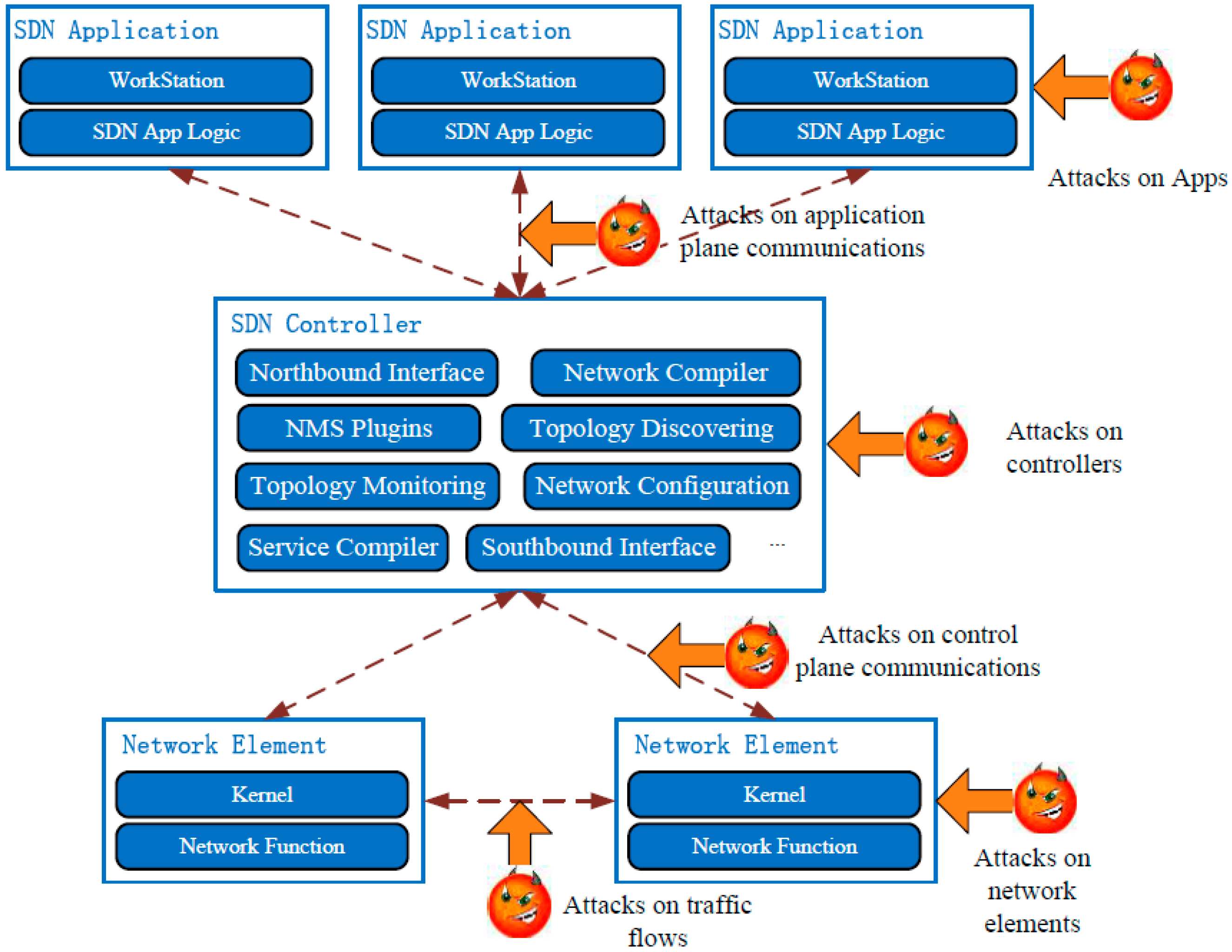
A comprehensive security attack vectors map of SDN is illustrated in Figure 1. Several attack vectors exist in applications, controllers, network elements and the links or traffic between them. Some of the attacks are common to all types of networks, such as the attack vectors on applications and network elements, but some of them only exist in SDN, such as the attack vectors on the SDN controller and the control links between the controller and network elements.
Figure 1. Security attack vectors of SDNs.
Sensors 15 29887 g001
There is already lots of research focusing on traditional network security assessment. In the earlier period, security assessment methods were only applicable to isolated components. However as multi-stage attacks have become the most harmful network security threats, these methods are not enough. The reason is that these methods did not consider the security holes introduced by the interconnections of local vulnerability [17]. To address the problem of security holes, attack graphs have been proposed as security assessment methods by building security models of network systems [17,18,19,20,21]. In the research of Dantu et al. [22], attack graphs are used to model network vulnerabilities. Then they perform a risk analysis by a Bayesian method. The Bayesian method is also used to model potential attack paths in a system described by Liu and Man in [23]. Based on the background knowledge of the attacker, including attack mechanism, they develop algorithms to compute attack paths. Poolsappasit et al. [24] use a Bayesian method to quantify the chances of network compromise. Moreover, they develop a security mitigation and management plan according to these results.
However, none of them can be applied directly in SDN-MNs because they only focus on traditional networks and do not take the special properties of SDN-MNs into consideration. Firstly, these methods are only suitable for relatively static networks. They do not take the dynamic nature of SDN-MNs into consideration. Secondly, the traditional algorithms of attack graph generation are only suitable for relatively simple networks. When the network becomes more complex, the efficiency of these algorithms deceases greatly, so these traditional methods cannot deal with the diversity and complexity of SDN-MNs.
Based on the aforementioned analysis, it is very necessary to have an effective security assessment mechanism for SDN-MNs considering their distinctive features. Firstly, a methodology to measure the total security level of SDN-MNs is needed. When SDN-MNs interconnect nodes in the network, local vulnerabilities will introduce new security holes because of this connectivity [17]. This methodology needs to not only deal with the security holes, but also deal with the diversity and complexity of SDN-MNs. Secondly, a way to quantify the influence caused by dynamic properties of SDN-MNs is important as well, so besides the methodology, what factors and how they influence SDN-MN security assessments must be taken into consideration.
To address these problems, a security assessment scheme for SDN-MNs using attack graphs and an Analytic Hierarchy Process (AHP) is proposed. The rest of the paper is organized as follows: a background on mobile network architectures and SDN-MNs is introduced in Section 2. The structure of the proposed security assessment methodology is described in Section 3. Section 4 presents the details of the proposed attack graph model and the attack graph generation algorithm. The Node Minimal Effort (NME) attack graph quantification method considering the dynamic factors in SDN-MNs is discussed in Section 5. In Section 6, a case study is illustrated. Finally, we conclude the paper in Section 7.

2. Background

In the past few years, data traffic in mobile networks has seen an explosive growth. The Long Term Evolution (LTE) network architecture has been adopted to meet this evolution and nowadays the LTE architecture has been widely adopted by mobile service providers around the world [9,10,11,12,13].
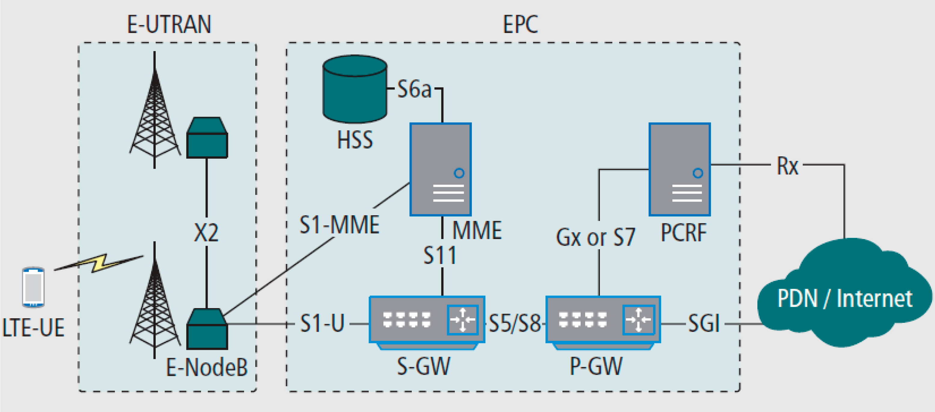
Figure 2 illustrates the LTE architecture proposed by the 3rd Generation Partnership Project (3GPP). It is composed of the LTE core network called the evolved packet core (EPC) and Evolved Universal Terrestrial Radio Access Network (E-UTRAN). EPC includes the packet data network gateway (P-GW), the serving gateway (S-GW) and so on.
Although it significantly improves network performance, LTE creates some new problems. Because all traffic goes through the P-GW in EPC, the P-GW becomes a bottleneck to extend the mobile network, and because each device in this architecture uses specialized hardware and software, it greatly increases the time and equipment costs of the operators when introducing new network functionalities into LTE.
In order to address these challenges, many recent researches have proposed and discussed new mobile network architectures for 5G based on Software-Defined Networking [9,10,11,12,13].
Figure 2. LTE network architecture.
Sensors 15 29887 g002
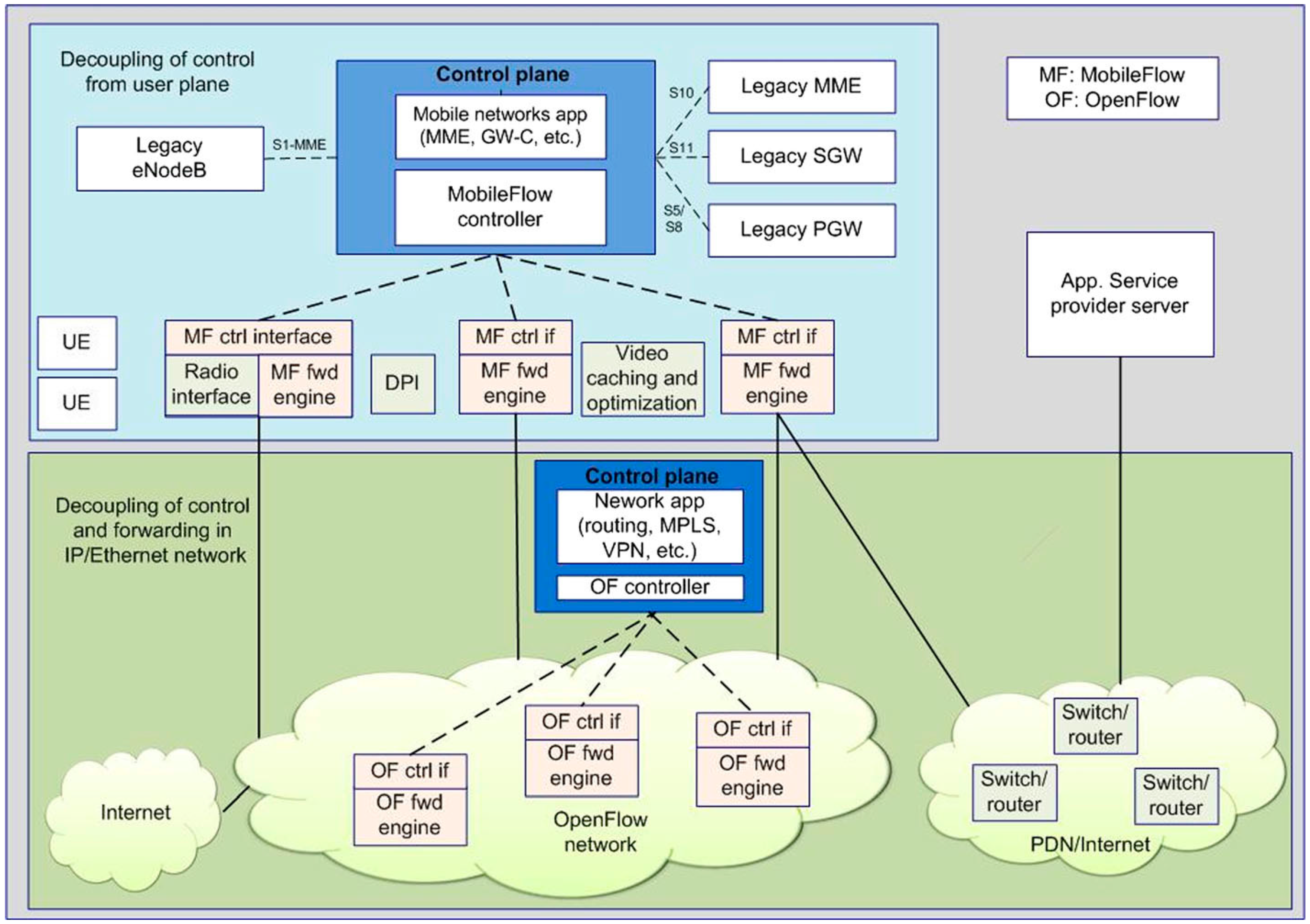
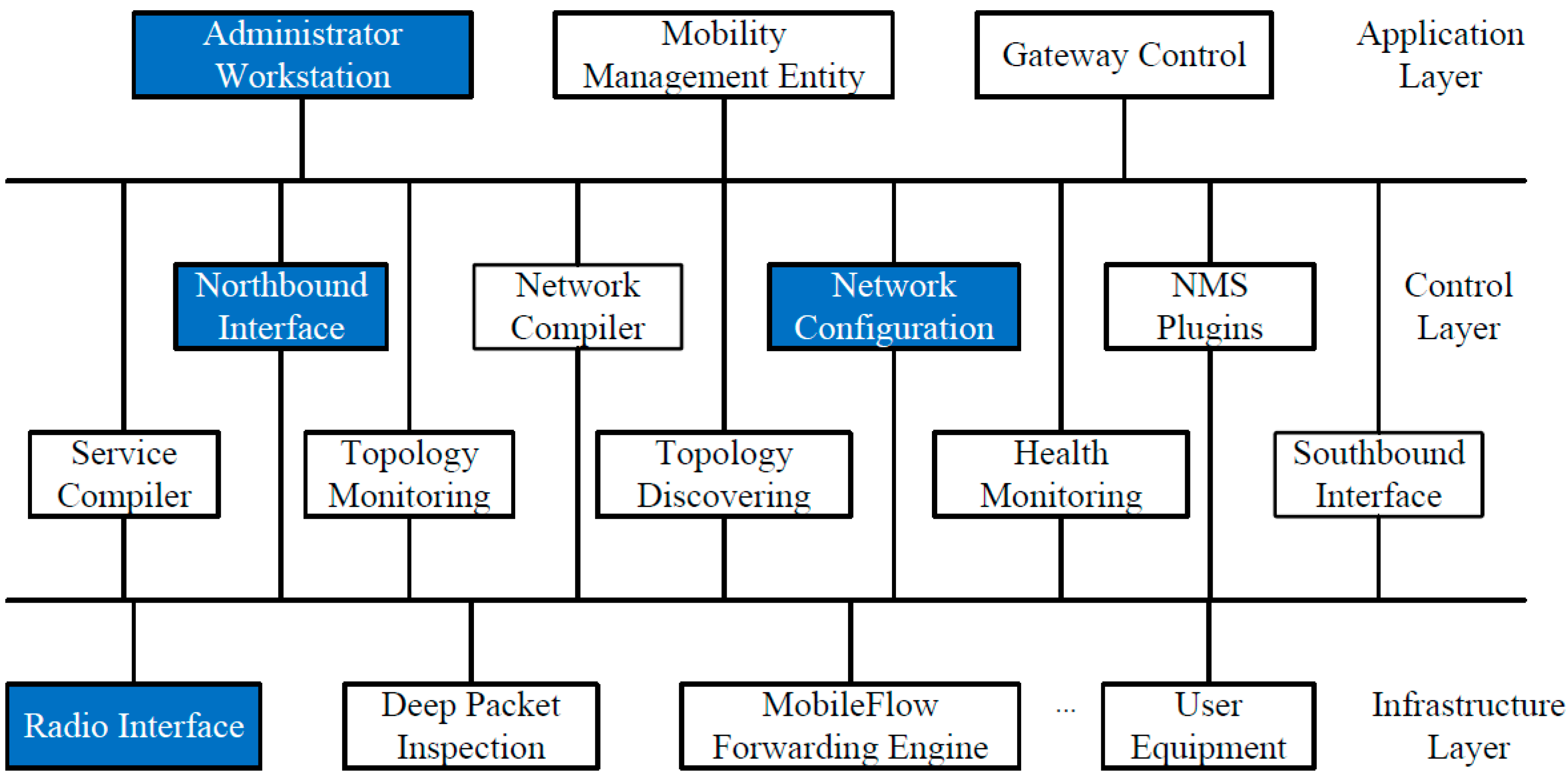
For example, MobileFlow, illustrated in Figure 3, is proposed as a SDN-based mobile network architecture in [10]. The key components in the MobileFlow architecture are the MobileFlow controller and the MobileFlow forwarding engine. Similar to the SDN architecture, MobileFlow separates mobile network control from all user plane elements. MFFEs are interconnected by the IP network and are fully software driven. MobileFlow uses the OpenFlow protocol for communication between controllers and switches and support network layer tunneling. This makes MobileFlow much simpler than traditional EPS elements.
Figure 3. The MobileFlow network architecture.
Sensors 15 29887 g003
In [9], the authors propose a SDN-based architecture of mobile networks named Software-Defined Wireless Networks (SDWN). In the SDWN architecture, programmability is widely introduced into Radio Access Networks (RANs) and the core transport. An API is enabled in order to allow third parties to control the network.
In [13], the authors propose another SDN-based mobile network architecture named Cellular SDN (CSDN). In the CSDN architecture, radio access networks allow the orchestration of resources using the SDN and NFV techniques. Additionally, these techniques are leveraged for service orchestration.

3. Basics of Security Assessment Methodology

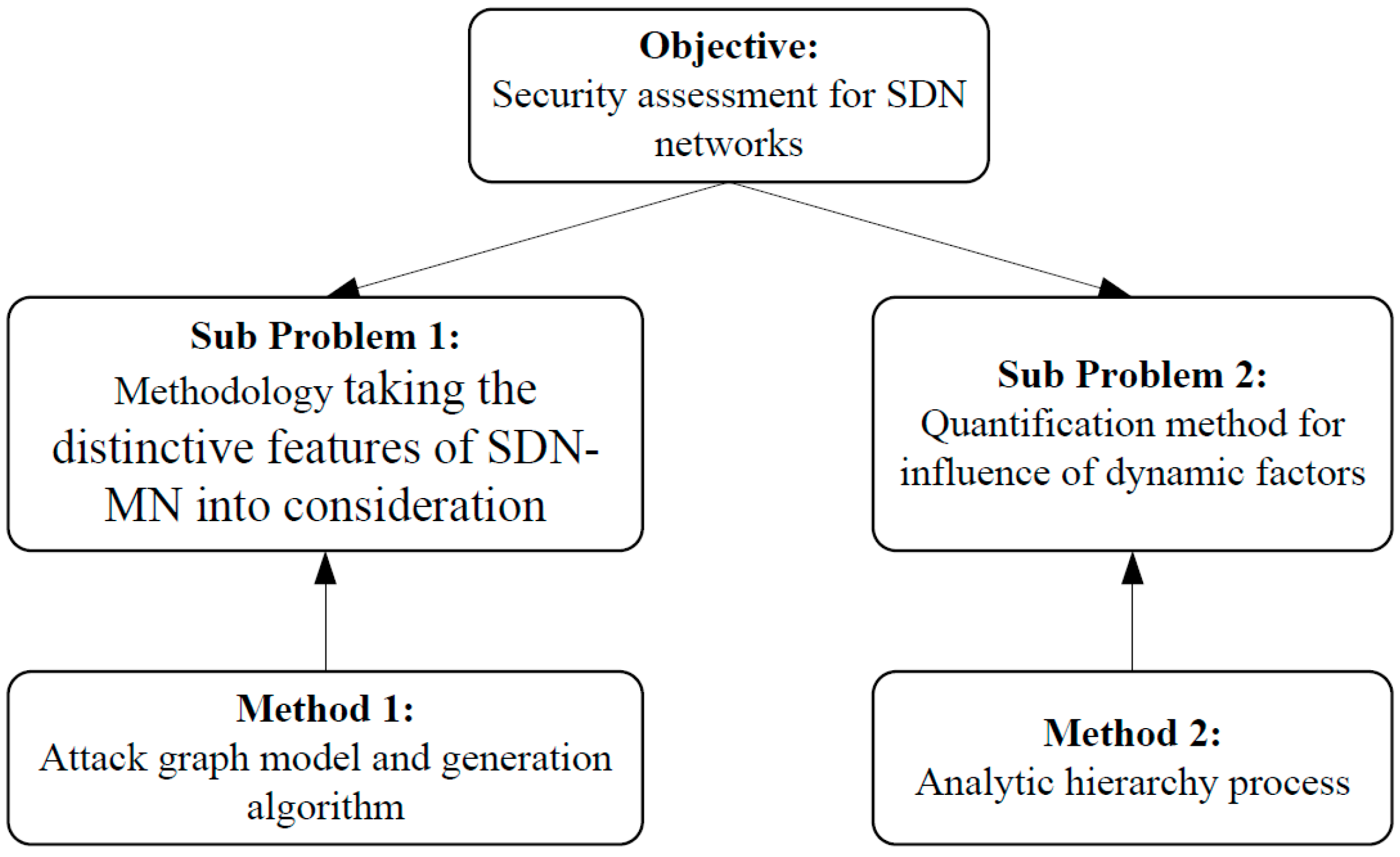
To provide a novel and complete methodology supporting the security assessment for SDN-MNs, there are two main questions that need to be considered. The first one is how to construct a complete security assessment methodology that can take the distinctive features of SDN-MNs into consideration. That means the methodology not only can take their dynamic nature into consideration, but also can promote the security assessment efficiency to address the complexity of SDN-MNs. The second one is how to quantify the security level of the network with regard to the various dynamic factors in SDN-MNs.
To construct the assessment methodology, we propose a novel attack graph modeling method to take the dynamic properties of SDN-MNs into consideration. To address the problem of attack graph scalability caused by the complexity of SDM-MNs, we propose a novel attack graph generation algorithm.
To quantify the security level of a SDN-MN, we define the NME that is used to derive the network security level. To calculate the NME with regard to the dynamic factors in an SDN-MN is a multiple criteria decision-making problem. We integrate AHP and the Technique for Order Preference by Similarity to an Ideal Solution (TOPSIS) to solve the problem. Expert knowledge is critical in the proposed methodology because AHP is a subjective method. The security assessment expert must know well the AHP and the SDN-MN itself. He or she can construct an AHP structure and appoint matrices according to the information collected from the network. The structure of the security assessment for SDN-MNs is illustrated in Figure 4.
Figure 4. Basic idea of security assessment for SDN-MNs.
Sensors 15 29887 g004

4. Modeling Network Attack Using Attack Graph

An attack graph is defined as a collection of all scenarios of how an attacker achieves its goal to target a system [24,25]. As mentioned before, to represent multi-stage network attacks and generate attack graphs, lots of models and methods have been proposed. There is a common efficiency problem in these attack graph generation algorithms, in that SDN-MNs are often diverse and complicated, so an efficient attack graph generation algorithm is a must.

4.1. Definition of Attack Graph and Generation Algorithm

To define and generate attack graphs for SDN-MNs, we use previous work of our group which proposed an attack graph generation algorithm to address the efficiency problem [26].
The basic concepts of attack graph are defined as follows:
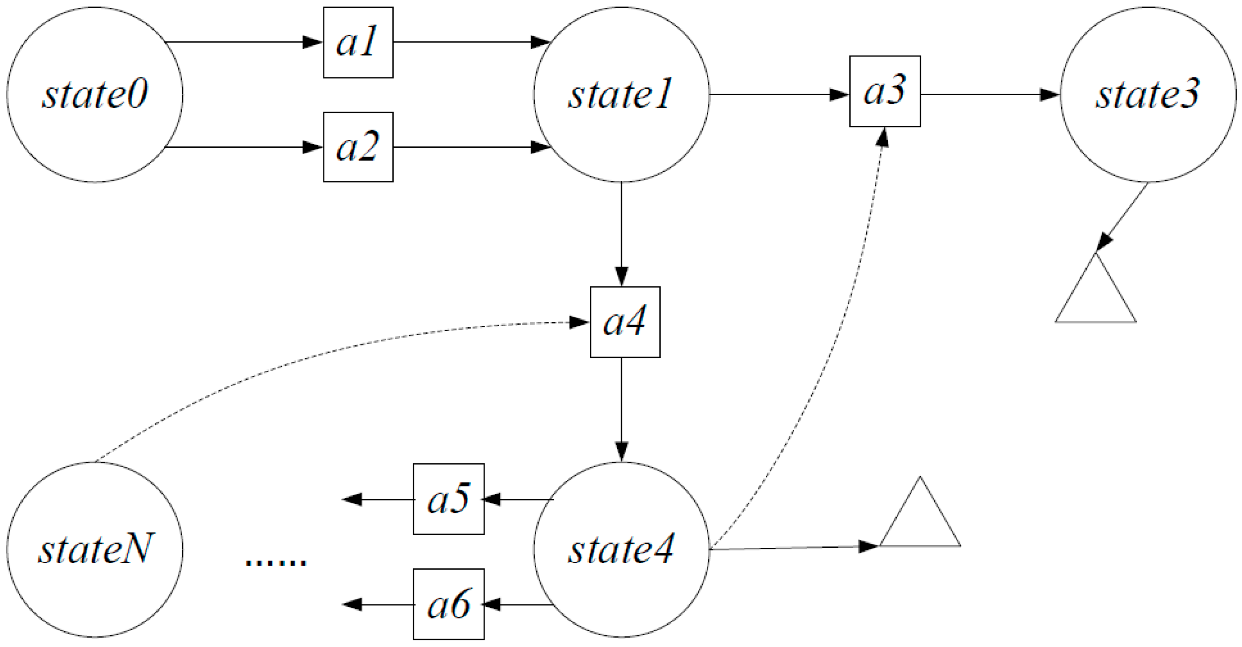
Definition 1: Attack Graph. An attack graph is defined as a tuple AG = ( A , S , G , E b , E f ) . In the definition, A denotes Action objects, S denotes State objects and G denotes Goal objects. Also E b denotes backward pointers. Finally, E f denotes forward pointers.
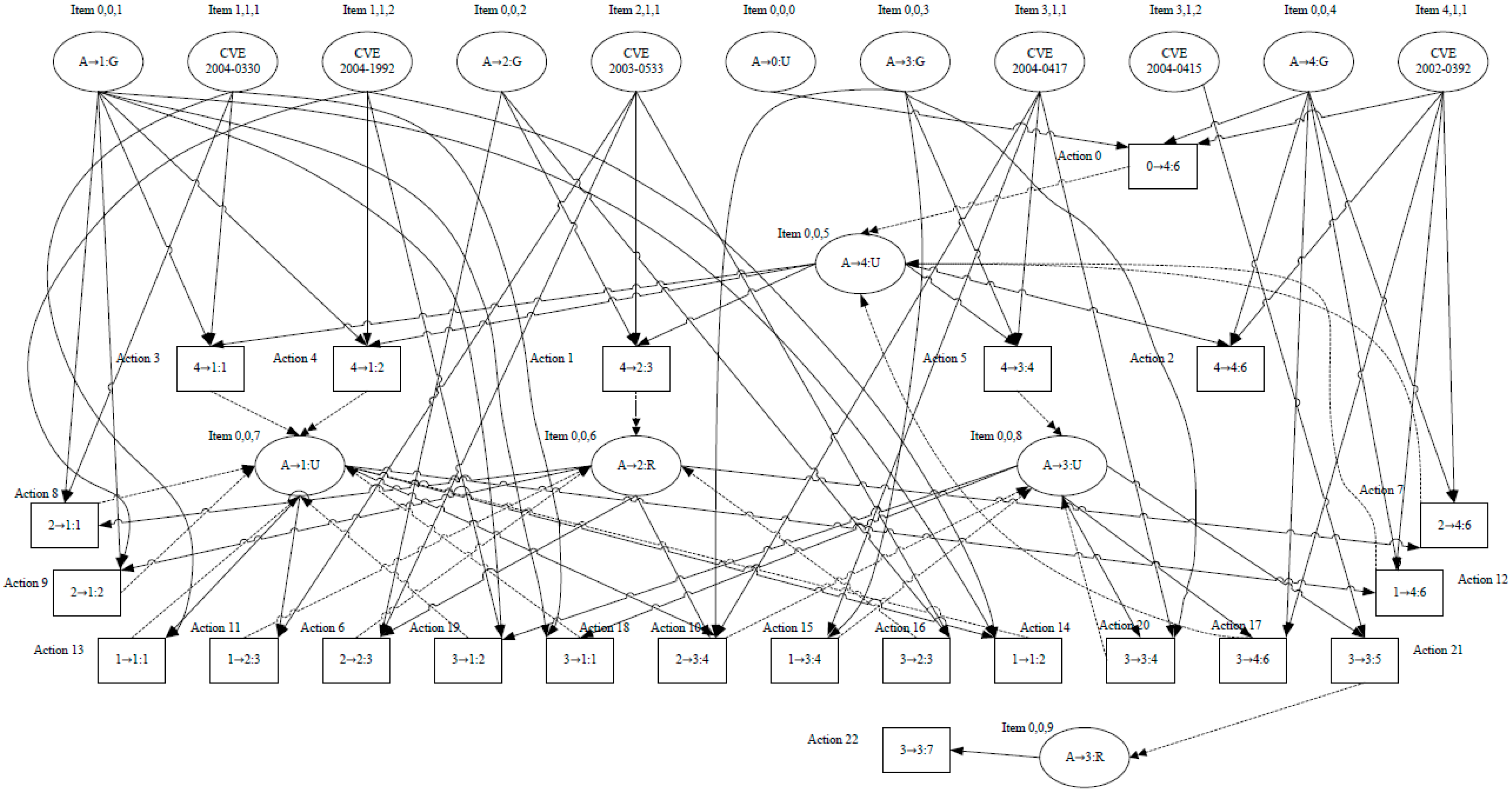
The attack graph definition is shown in Figure 5. In Figure 5, real lines denote forward pointers and dotted lines denote backward pointers. Rings identify the instances of State objects, and squares represent the instances of Action objects, and triangles represent the instances of Goal objects.
Figure 5. Attack graph definition for SDNs.
Sensors 15 29887 g005
In the example, state0 is the initial security state of the network. When action a1 or a2 is performed, the security state transfers to state1. Based on state1, if the attacker performs action a3, the security state continues to transfer to state3. At the end, the attacker reaches the attack goal. The rest of the attack graph has the same meaning.
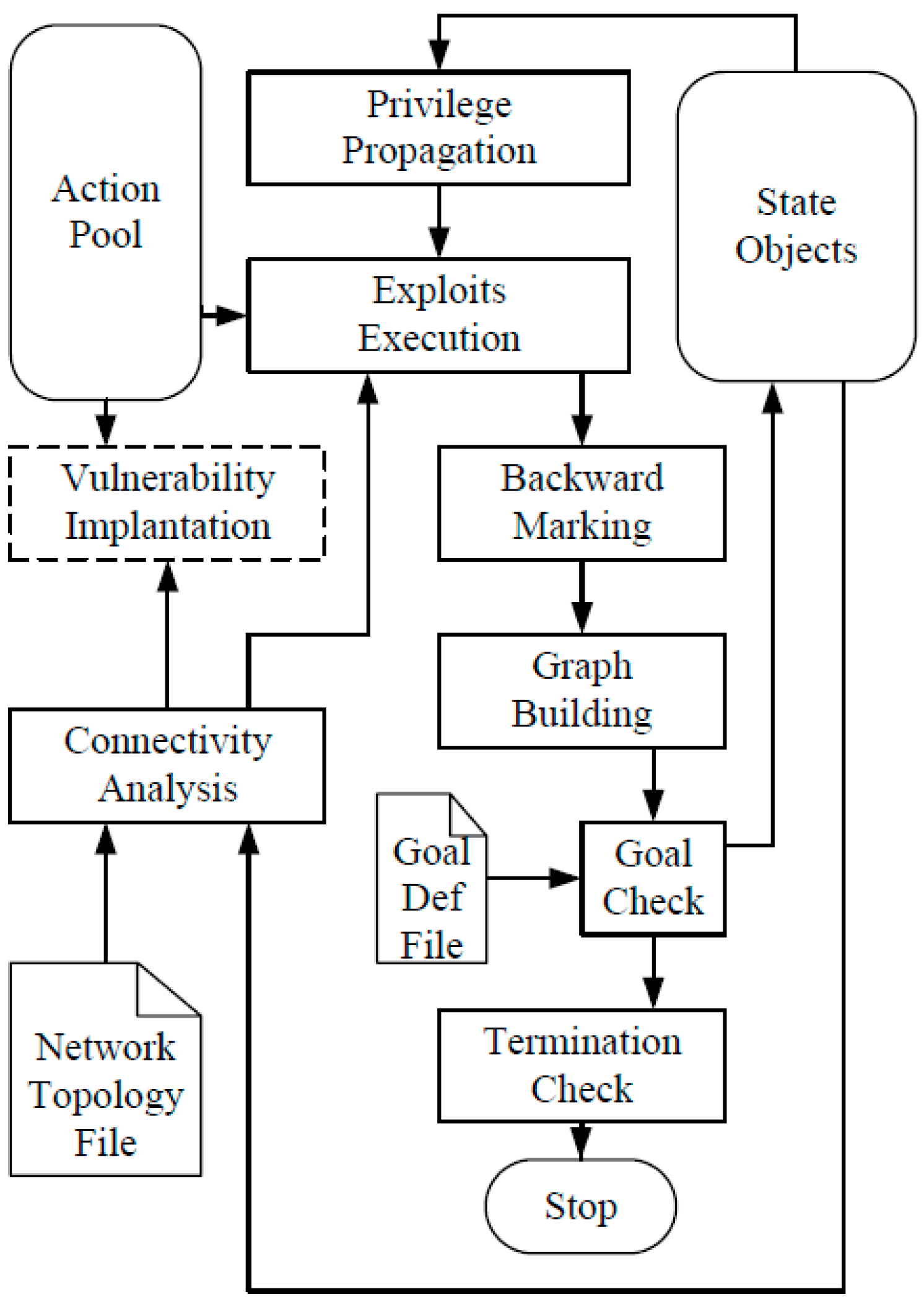
According to the definition of attack graph given above, the attack graph generation algorithm generates attack graphs based on a network knowledge base. The network knowledge base includes vulnerabilities, network connectivity, etc. We use a “state evolution process” algorithm to generate attack graphs. The state evolution process is illustrated in Figure 6.
Figure 6. State evolution process for an attack graph.
Sensors 15 29887 g006
Until the process meets termination condition, state objects are recursively evolving in the process. In each cycle, the process applies all possible malicious actions. The process includes several function entities as follows:
(1)
Privilege propagation entity
The privilege propagation function entity is responsible for propagate the privilege according to the current network state.
(2)
Connectivity analysis entity
The connectivity analysis function entity firstly analyzes the network topology and filtering policy information and then it produces the connectivity between any two nodes.
(3)
Exploits execution entity
The exploits execution function entity tries to apply all exploit objects to the state objects.
(4)
Backward marking entity
The backward marking function entity removes all the former indicates. After actions are applied, it marks re-satisfied items with a fresh indicate for the consequences.
(5)
Graph building entity
The graph building function entity generates a forward pointer or backward pointer according to the actions’ trigger.
(6)
Goal check entity
The goal check function entity confirms whether the attack is successful in the current security context.
(7)
Termination check entity
The termination check function entity confirms whether the process has no more ways to evolve. The process should be terminated once there is not a forward pointer. After a complete procedure, the generated attack graph is derived. For more detailed information about the sub-modules of the process readers can refer to [26].

4.2. Node Minimal Effort

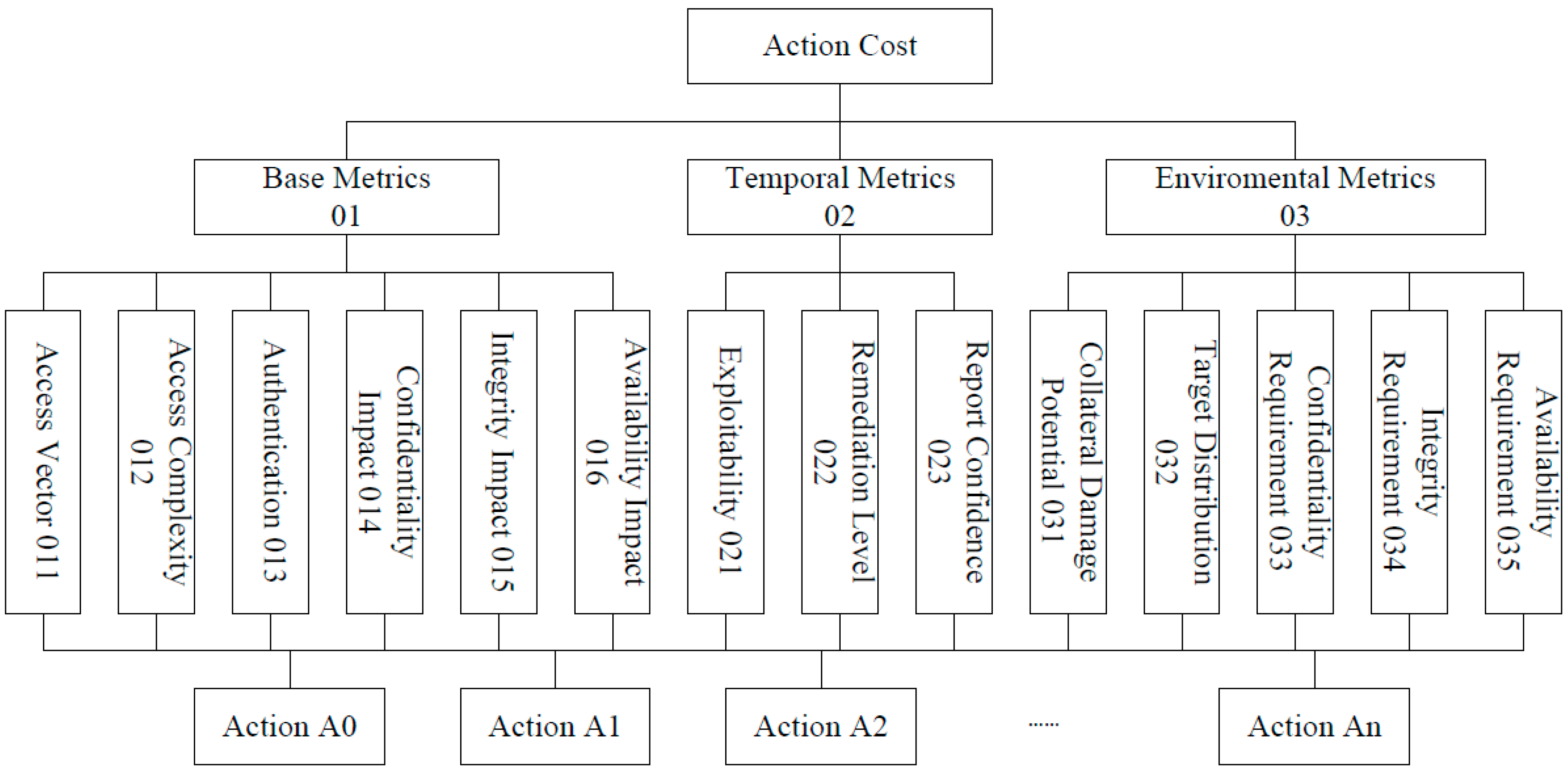
Attack cost is the expense for an attacker to achieve an attack goal. We use attack cost in attack graphs to quantify the security level of the network. Namely, when the attack cost is higher, the network is more secure and vice versa. Normally, there are several actions in one attack behavior. We define action cost to designate the expense for an attacker to perform an action. To evaluate the attack cost of an attack path, we define NME for the nodes in the attack graph:
Definition 2: In an attack graph, NME is the minimal attack cost to reach a node.
There are two types of nodes in our attack graph definition, namely state node and action node. In general, the minimal effort of a state node is the attack cost of the attack path that leads to the state node. If there are several attack paths that leads to the state node, the minimal effort of the state is minimal attack cost in the attack paths. Because of the AND relation, the minimal effort of an action node equal all the NMEs of its prerequisite nodes plus the action cost of itself.
Let min_effort denotes NME, min_effort calculated as follows:
  • for state node s S ,
min_effort ( s ) = 0 ,   if s   is the initial state; min_effort ( s ) = min k ( min_effort ( a k ) )
where   a k denotes a instance of the prerequisite nodes of s .
  • for action node   a A ,
min_effort ( a ) = k min_effort ( s k ) + effort ( a )
where   s k denoted a instance of the prerequisite nodes of a , and effort ( a ) denotes the attack cost of a .

5. Quantification of NME Using AHP and TOPSIS

As mentioned before, the NME of a node equals to NMEs of its prerequisite nodes plus its own action cost, so the action cost is the basic variable and all the NMEs are derived from the action cost. The action cost is under the constraints of certain vulnerability and the dynamic factors of the network. This is a multiple criteria decision-making problem.
As AHP has been demonstrated to be an excellent multi-criteria decision-making approach in the past years, we adopt AHP to quantify the action cost and derive NME. To countermeasure the competitive benchmarking of the security properties for AHP, we integrate the technique for order preference by similarity to ideal solution (TOPSIS). This is because TOPSIS is an excellent compensatory aggregation method. We calculate action cost with the following steps:
Step 1:
Construct the hierarchical security factors structure. In this step, we divide the hierarchical structure into four different layers.
Step 2:
Calculate the weights of factors at each layer in the hierarchy using AHP. This step mainly includes deriving matrix data, calculating the weights of indicators, evaluating the consistency ratio and constructing combinatorial weights.
Step 3:
Calculate the attack cost of actions in the dynamic environment using TOPSIS. This step mainly includes decision matrix normalization and so on. Finally, it calculates the attack cost of actions.

5.1. Construct Hierarchical Structure

To quantify the attack cost of actions in a dynamic environment, we firstly need to construct the hierarchical structure of different security factors. We divide the hierarchical structure into four different layers in this paper. Firstly, the top layer is the goal layer. In our paper, the goal is to determine the action cost. Below the top layer, there is the criteria layer. This layer includes the main types of metrics groups for security assessment. Below the criteria layer, there is the indicator layer. In this layer, we subdivide the metrics group into single metrics and we construct the action layer as the forth layer. In this layer, actions involved in the attack graph are included. We use the Common Vulnerability Scoring System (CVSS) as the basic for the structure [27,28]. Figure 7 shows the hierarchy.
Figure 7. Hierarchical structure of security factors.
Sensors 15 29887 g007

5.2. Calculate the Weights of Factors Using AHP

Pair-wise comparison is the basis of the AHP analysis [29]. We use the pair-wise comparison scale for AHP preferences as in [29].

5.2.1. Matrix Data

Once the hierarchy has been constructed, we determine the pair-wise comparison matrix. According to the AHP method, we first construct the pair-wise comparison matrix A:
A = ( a i j ) n × n = [ 1 a 12 a 21 1 a 1 n a 2 n a n 1 a n 2   1 ]
In matrix A, the parameter a i j represents the relative importance of the i th factor compared to the j th factor, and a i j = 1 a j i .

5.2.2. Weights of Indicators

The indicator weight can be derived from the relevant normalized eigenvector W = ( w 1 , w 2 , , w n ) of corresponding matrix A as follows:
A W = λ max W
In the equation, λ m a x represents the largest eigenvalue of matrix A.

5.2.3. Consistency Ratio

We use the following steps to evaluate the consistency ratio (CR) of the estimated vectors:
Step 1: Calculate the eigenvector and λ m a x for each matrix.
Step 2: Compute the consistency index (CI) as follows:
C I = ( λ m a x - n ) / ( n - 1 )
Step 3: Calculate CR as follows:
C R = C I / R I
RI is a known random consistency index. It is derived from the average index of randomly generated weights. A CR value must be less than 0.10. Otherwise, we must reapportion the parameters of matrix A.

5.2.4. Construct Combinatorial Weights

The last step in AHP procedure is to construct the combinatorial weight:
W ( i ) = ( W 1 ( i p ) , W 2 ( i p ) , , W n ( i p ) ) W ( p )
In the equation, W ( p ) represents the criteria layer combinational weight vector, and ( W 1 ( i p ) , W 2 ( i p ) , , W n ( i p ) ) represents the indicator layer weight matrix.

5.3. Calculate the Attack Cost of Actions using TOPSIS

After constructing the matrix A, the values of the vulnerability factors should be standardized and the attack cost of actions in the dynamic environment is calculated. Both of them use the TOPSIS method.

5.3.1. Normalize Decision Matrix

The matrix A is normalized to form the normalized decision matrix T:
T = ( T i j ) m × n
The normalization method is as follows:
t i j = a i j / j = 1 n a i j 2 , i = 1 , 2 , , m , j = 1 , 2 , , n

5.3.2. Compute the Weighted Normalized Decision Matrix and Alternatives

The weighted normalized decision matrix F is derived as follows:
F = T W
In the equation, W represents a diagonal matrix. The matrix is composed by the weight in W ( i ) .
Define the best alternative V + and the worst alternative V - :
V + = ( v 1 + , v 2 + , , v n + )
V - = ( v 1 - , v 2 - , , v n - )
Let I denotes the benefit criteria, and J denotes the cost criteria. Then the values of V + and V - can be calculated as follows:
v i + = { max ( f i j ) | i I } , { min ( f i j ) | i J }
v i - = { min ( f i j ) | i I } , { max ( f i j ) | i J }

5.3.3. Calculate the Attack Cost of Actions

Derive the L2-distance between alternative i and V + as follows:
s i + = j = 1 n ( v i j - v j + ) 2
Also, derive the L2-distance between alternative i and V - as follows:
s i - = j = 1 n ( v i j - v j - ) 2
Based on the distances, we calculate the attack costs of actions by the following formula:
cost i = s i + s i + + s i - , i = 1 , 2 , m

6. Case Study

6.1. Case Network

We provide a SDN-MN case based on the MobileFlow architecture [10] and Kumar's solution [30] as an example of a security assessment. Based on [10], we construct the whole network layers and some main network components special to SDN-MN. Based on [30], we detail the components of the MobileFlow controller. As shown in Figure 8, the network is divided into three layers. The application layer includes various applications utilizing the SDN-MN controller to manipulate the network infrastructure. The control layer includes the SDN-MN controller components, such as application interface, service compiler, network compiler, etc. The infrastructure layer includes the radio interface, deep packet inspection, MobileFlow forwarding engine, user equipment, etc.
We suppose some of the function modules in the network are vulnerable. The vulnerable modules include the “Administrator Workstation” module, “Northbound Interface” module, “Network Configuration” module, and “Radio Interface” module. The vulnerabilities and their details are listed in Table 1.
Figure 8. Case of Software-Defined mobile network.
Sensors 15 29887 g008
Table 1. Details of vulnerabilities in case network.
IDNode NameCVE#Detail
1“Administrator Workstation” moduleCVE-2004-0330Vulnerability that allows remote users to execute arbitrary code in some Serv-U versions.
CVE-2004-1992Vulnerability that allows remote attackers to execute DoS in some Serv-U versions.
2“Northbound Interface” moduleCVE-2003-0533Stack buffer overflow in Active Directory service.
3“Radio Interface” moduleCVE-2004-0417Integer overflow in some CVS versions.
CVE-2004-0415Vulnerability that allows local users to access portions of kernel memory.
4“Network Configuration” moduleCVE-2002-0392Vulnerability that allows remote attackers to execute DoS and execute arbitrary codes.
To explain the influence toward the security assessment results of dynamic factors, we define two schemes. The two schemes differ in the decision matrix. This means certain actions affect the security differently in different environments.

6.2. Security Model for Analysis

We suppose that the attacker wants to hack the “Radio Interface” module and then ultimately disable the “Radio Interface” module, that is, the “Radio Interface” module is the ultimate target of the attacker. We generate the attack graph to attack the “Radio Interface” module as shown in Figure 9 using the proposed attack graph generation algorithm.
In Figure 9, a circle denotes the State object labeled “Item x, y, z”. The number x denotes the object ID in Table 1. The number y denotes the type of object. The number z denotes the instance ID of the object, and the text in the circle is a description of the item. A square denotes an Action object and other components are defined in Definition 1.
Figure 9. Generated attack graph case.
Sensors 15 29887 g009
There are in total 23 actions in the attack graph.

6.3. Calculate the Values of the Actions Costs

In this section, we collect data of the AHP matrices. In our case, the AHP matrices are illustrated in Table 2, Table 3, Table 4 and Table 5. The decision matrixes of actions compared to the indicators of the two schemes are listed in Table 6. We call the first scheme the “Network Administrator” scheme. In this scheme, to provide the network administrator convenience to manage the network, the “Network Configuration” module is accessed easily. We call the second scheme the “Application User” scheme. In this scheme, to provide the application user convenience to call the Northbound API, and the “Northbound Interface” module is accessed easily.
Table 2. AHP matrix of the criteria layer.
010203
0111/31/5
02311/2
03521
Table 3. No. 01 AHP matrix of the indicator layer.
011012013014015016
011111/31/31/21/2
012111/31/31/21/2
01333111/21/2
01433111/21/2
015222211
016222211
Table 4. No. 02 AHP matrix of the indicator layer.
021022023
021121/2
0221/211/3
023231
Table 5. No. 03 AHP matrix of the indicator layer.
031032033034035
03111/3312
03231635
0331/31/611/21
03411/3212
0351/21/511/21
Table 6. Decision matrix in our case.
“Network Administrator” Scheme“Application User” Scheme
0111311351113113513511113115553955155539553955515
0121322352213223522522113215663966156639663966615
0131322462213224622462211315664966156649664966615
0143433463334334633463313437774774377747744777437
0153344364333443643364313337773773377737733777337
0168751551187515511551118782515211825152115211182
0213634684136346841684113647457952474579527955247
0223634684136346841684113636346841363468416841136
0232513563125135631563112558568962585689628962258
0315911991159119911991115959119911591199119911159
0321111711111117111711111111777171117771717171111
0337355635373556353635337373556353735563536353373
0347577657375776573657337575776573757765736573375
0357555655375556553655337575556553755565536553375
Finally, we calculate the values of the attack costs of actions of the two schemes using the formulas in Section 4. The result is shown in Figure 10.
Figure 10. Attack cost values of actions.
Sensors 15 29887 g010

6.4. Calculate the Minimal Effort and Get the Shortest Attack Path

Based on the values of the actions attack costs and the definition of NME, we can draw the two shortest attack paths of the schemes and the corresponding minimal efforts separately for the “Radio Interface” module. Figure 11 shows the shortest attack paths of the two schemes separately.
Figure 11. Shortest attack paths: (a) “Network Administrator” scheme; (b) “Application User” scheme.
Sensors 15 29887 g011
In both schemes, action 22 is the last node of the corresponding attack paths, so the NME of action 22 can designate the security level of the network.
According to the action attack cost and min_effort equation values, we can calculate the minimal effort of action 22 in the two schemes separately. Let min_effort1 denote the NME value in the “Network Administrator” scheme and min_effort2 denote the NME value in the “Application User” scheme. In addition, let c o s t   ( a i ) denote the cost of the ith action. Then, the values are calculated as follows:
min_effort 1 = i = 0 , 5 , 21 , 22 cost ( a i ) = 1.34
min_effort 2 = i = 1 , 10 , 21 , 22 cost ( a i ) = 1.56
The NME of action 22 in the “Network Administrator” scheme is 1.34, and the NME of action 22 in the “Application User” scheme is 1.56. Intuitively, the cost of exploitation of CVE2002-0392 is less expensive than CVE2003–0533 in the “Network Administrator” scheme, so in the “Network Administrator” scheme the attack is launched from the “Network Configuration” module easier than from other modules. However, in the “Application User” scheme, the cost of exploitation of CVE2002-0392 is more expensive than CVE2003–0533 because of the change of the network factors, so the initial node of attack is the “Northbound Interface” module. From the example, we can learn that when the network factors vary, the minimal effort of action 22 varies.

7. Conclusions and Future Work

SDN-MNs provide many advantages for 5G mobile networks, but they also introduce new security challenges into the networks. The main problem is how to measure the security level of SDN-MNs. In this paper, we have proposed a novel security assessment mechanism for SDN-MNs. We analyze the new characteristics of SDN-MNs and find that SDN-MNs introduce a dynamic nature and complexity into mobile networks. The traditional network security assessment mechanisms cannot be directly applied to SDN-MNs. To solve the new security problems, we propose a security assessment methodology based on attack graphs and an analytic hierarchy process. A novel definition and attack graph generation algorithm are proposed to address the complexity of SDN-MNs. Also, we define NME as the index value of a security assessment to capture the quantitative dynamic property influence of SDN-MNs. By evaluating our scheme, we prove that our security assessment mechanism can deal precisely with the distinctive features of SDN-MNs and is very effective for security assessment for SDN-MNs. However, we use the classical AHP in our mechanism, so there are still margins for improvement. The classical AHP has the property of unbalanced scale of judgment. In the pair-wise comparison process, it is not precise to solve the inherent uncertainty and vagueness. In the future, it would be useful to employ a fuzzy AHP approach [31]. With a fuzzy AHP approach, quantifications of attack costs would become more precise.

Acknowledgments

This work was supported in part by National Natural Science Foundation of China under Grant No. 61431008, 61401273. Additionally, this work was supported in part by the JSPS KAKENHI Grant No. 26730056, 15K15976 and JSPS A3 Foresight Program..

Author Contributions

Shibo Luo, Jun Wu and Jianhua Li contributed to the methodology, attack graph and TOPSIS of security assessment, Mianxiong Dong and Kaoru Ota contributed to verification of the experiments.

Conflicts of Interest

The authors declare no conflict of interest.

References

  1. Kreutz, D.; Ramos, F.M.V.; Verissimo, P.E.; Rothenberg, C.E.; Azodolmolky, S.; Uhlig, S. Software-Defined Networking: A Comprehensive Survey. Proc. IEEE 2015, 103, 14–76. [Google Scholar] [CrossRef]
  2. Open Networking Foundation. Software-Defined Networking: The New Norm for Networks; Open Networking Foundation: Palo Alto, CA, USA, 2012. [Google Scholar]
  3. Dong, M.; Li, H.; Ota, K.; Xiao, J. Rule caching in SDN-enabled mobile access networks. IEEE Netw. 2015, 29, 40–45. [Google Scholar] [CrossRef]
  4. Xia, W.; Wen, Y.; Foh, C.H.; Niyato, D.; Xie, H. A Survey on Software-Defined Networking. IEEE Commun. Surv. Tutor. 2015, 17, 21–57. [Google Scholar] [CrossRef]
  5. Dong, M.; Liu, X.; Qian, Z.; Liu, A.; Wang, T. QoE-ensured price competition model for emerging mobile networks. IEEE Wirel. Commun. 2015, 22, 50–57. [Google Scholar] [CrossRef]
  6. Dong, M.; Kimata, T.; Sugiura, K.; Zettsu, K. Quality-of-Experience (QoE) in Emerging Mobile Social Networks. IEICE Trans. 2014, 97, 2606–2612. [Google Scholar] [CrossRef]
  7. Bernardos, C.J.; de La Oliva, A.; Serrano, P.; Banchs, A.; Contreras, L.M.; Hao, J.; Zúniga, J.C. An architecture for software defined wireless networking. IEEE Wirel. Commun. 2014, 21, 52–61. [Google Scholar] [CrossRef]
  8. Pentikousis, K.; Wang, Y.; Hu, W. MobileFlow: Toward Software-Defined Mobile Networks. IEEE Commun. Mag. 2013, 51, 44–53. [Google Scholar] [CrossRef]
  9. Jin, X.; Li, L.E.; Vanbever, L.; Rexford, J. Softcell: Scalable and Flexible cellular core network architecture. In Proceedings of ninth ACM Conference on Emerging Networking Experiments and Technologies, Santa Barbara, CA, USA, 9–12 December 2013.
  10. Tomovic, S.; Pejanovic-Djurisic, M.; Radusinovic, I. SDN Based Mobile Networks: Concepts and Benefits. Wirel. Pers. Commun. Int. J. 2014, 78, 1629–1644. [Google Scholar] [CrossRef]
  11. Bradai, A.; Singh, K.; Ahmed, T.; Rasheed, T. Cellular Software Defined Networking: A Framework. IEEE Commun. Mag. 2015, 23, 36–43. [Google Scholar] [CrossRef]
  12. Guo, L.; Wu, J.; Xia, Z.; Li, J. Proposed Security Mechanism for XMPP Based Communications of ISO/IEC/IEEE 21451 Sensor Networks. IEEE Sens. J. 2015, 15, 2577–2586. [Google Scholar] [CrossRef]
  13. Scott-Hayward, S.; Sezer, S. SDN Security: A Survey. In Proceedings of the 2013 IEEE SDN for Future Networks and Services, Trento, Italy, 11–13 November 2013.
  14. Benton, K.; Camp, L.J.; Small, C. OpenFlow Vulnerability Assessment. In Proceedings of the 2nd ACM SIGCOMM workshop on Hot topics in software defined networking, Hong Kong, China, 16 August 2013.
  15. Kreutz, D.; Ramos, F.; Verissimo, P. Towards secure and dependable software-defined networks. In Proceedings of the 2nd ACM SIGCOMM workshop on Hot topics in software defined networking, Hong Kong, China, 16 August 2013.
  16. Porras, P.; Shin, S.; Yegneswaran, V.; Fong, M.; Tyson, M.; Gu, G. A security enforcement kernel for openflow networks. In Proceedings of the 1st workshop on Hot topics in software defined networks, Helsinki, Finland, 13 August 2012.
  17. Ammann, P.; Wijesekera, D.; Kaushik, S. Scalable, Graph Based Network Vulnerability Analysis. In Proceedings of the 9th Conference Computer and Communications Security, Washington, DC, USA, 18–22 November 2002.
  18. Jha, S.; Sheyner, O.; Wing, J.M. Two Formal Analyses of Attack Graphs. In Proceedings of the 15th IEEE Computer Security Foundations Workshop, Cape Breton, NS, Canada, 24–26 June 2002.
  19. Phillips, C.; Swiler, L.P. A Graph-Based System for Network Vulnerability Analysis. In Proceedings of the New Security Paradigms Workshop, Charloltsville, VA, USA, 15–18 September 1998.
  20. Sheyner, O.; Haines, J.; Jha, S.; Lippmann, R.; Wing, J.M. Automated Generation and Analysis of Attack Graphs. In Proceedings of IEEE Symposium on Security and Privacy, Berkeley, CA, USA, 12–15 May 2002.
  21. Swiler, L.P.; Phillips, C.; Ellis, D.; Chakerian, S. Computer Attack Graph Generation Tool. In Proceedings of the Second Defense Advanced Research Projects Agency (DARPA) Information Survivability Conference and Exposition, Anaheim, CA, USA, 12–14 June 2001.
  22. Dantu, R.; Loper, K.; Kolan, P. Risk Management Using Behavior Based Attack Graphs. In Proceedings of the International Conference Information Technology: Coding and Computing, Nevada, LA, USA, 5–7 April 2004.
  23. Liu, Y.; Man, H. Network Vulnerability Assessment Using Bayesian Networks. In Proceedings of the SPIE, Orlando, FL, USA, 28 March 2005.
  24. Poolsappasit, N.; Dewri, R.; Ray, I. Dynamic Security Risk Management Using Bayesian Attack Graphs. IEEE Trans. Depend. Secur. Comput. 2012, 9, 61–74. [Google Scholar] [CrossRef]
  25. Sheyner, O.M. Scenario Graphs and Attack Graphs. Ph.D. Thesis, Carnegie Mellon University, Pittsburgh, PA, USA, 2004. [Google Scholar]
  26. Zhang, S.; Li, J.; Chen, X.; Fan, L. Building network attack graph for alert causal correlation. Comput. Secur. 2008, 27, 188–196. [Google Scholar] [CrossRef]
  27. US-CERT Vulnerability NoteField Descriptions. Available online: http://www.kb.cert.org/vuls/html/fieldhelp (accessed on 11 September 2015).
  28. Common Vulnerability Scoring System (CVSS). Available online: http://www.first.org/cvss/cvss-guide.html (accessed on 11 September 2015).
  29. Saaty, T.L. The Analytic Hierarchy Process; McGrawHill: New York, NY, USA, 1980. [Google Scholar]
  30. Sundararajan, R.K. Software Defined Networking (SDN)—A Definitive Guide; Kloudspun Press: Plano, TX, USA, 2013. [Google Scholar]
  31. Chen, S.J.; Hwang, C.L. Fuzzy Multiple Attributes Decision Making: Methods and Applications; Springer: Berlin, Germany, 1992. [Google Scholar]

