
Smart Device-Supported BDS/GNSS Real-Time Kinematic Positioning for Sub-Meter-Level Accuracy in Urban Location-Based Services

Abstract
:1. Introduction
2. System Design Scheme and Implementation
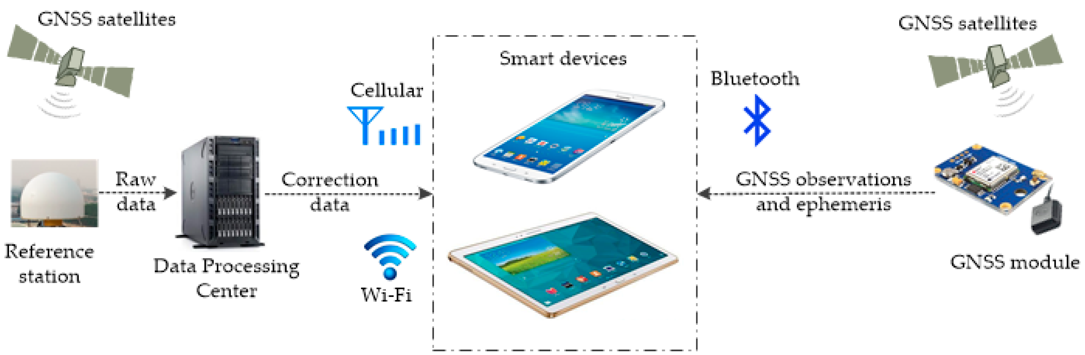
2.1. System Design Scheme
2.2. Mathematical Model
2.3. Ambiguity Resolution and Validation
2.4. Latency Time of the Differential Corrections
2.4.1. Analysis of the Latency Time of the Differential Corrections
2.4.2. Analysis of the Effect of Latency Time on RTK Positioning
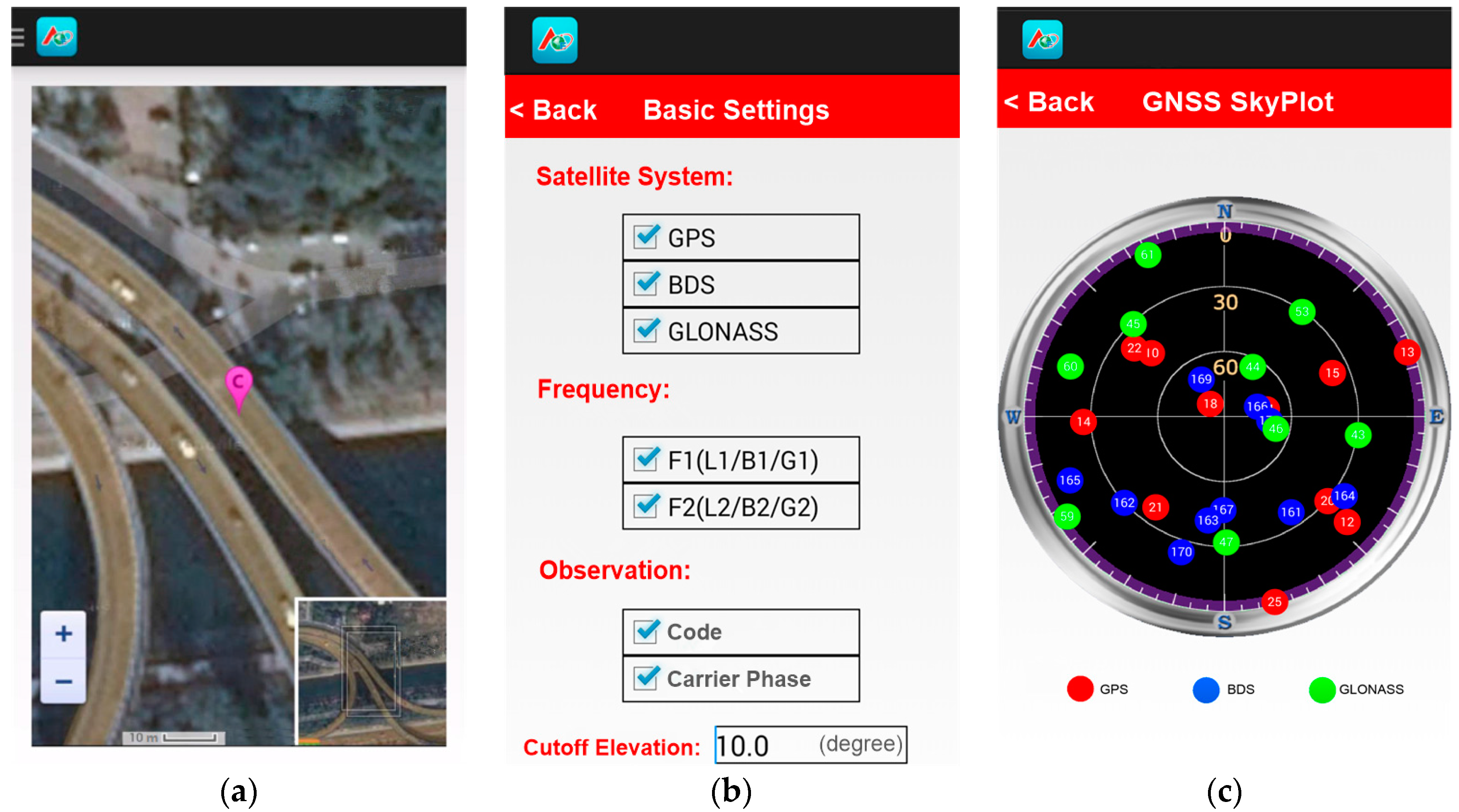
2.5. Software Implementation
3. Experiments and Results
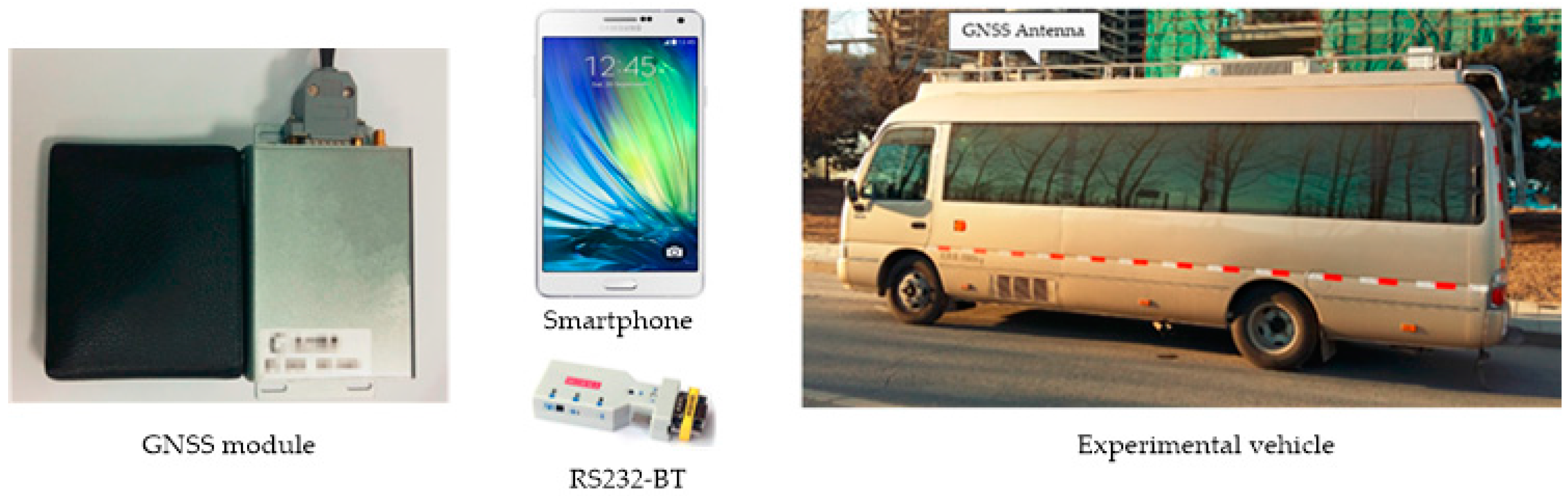
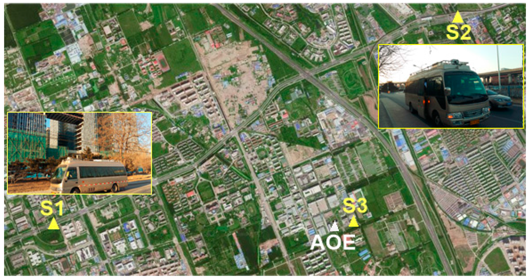
3.1. Outline of the Experiments
3.2. Results
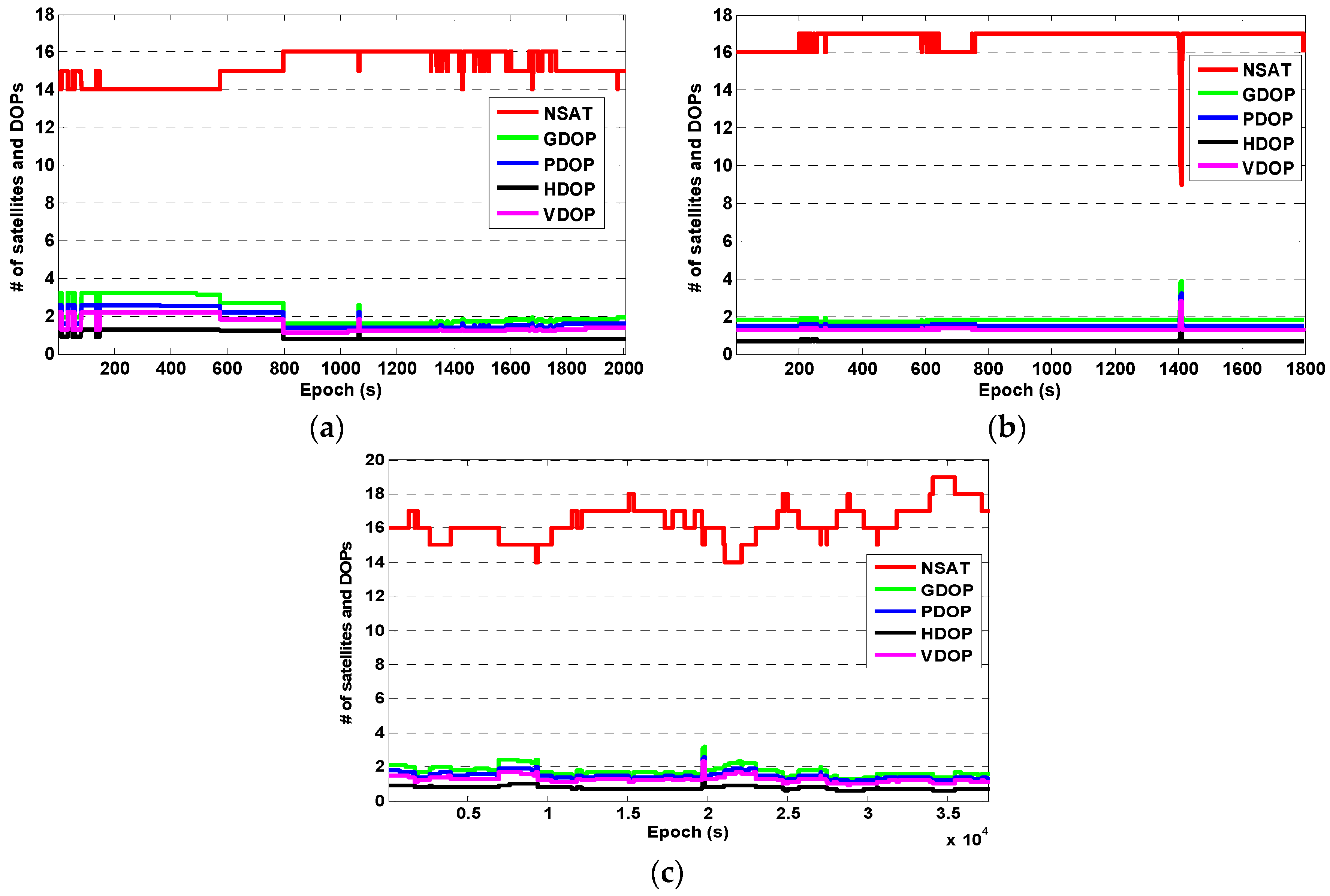
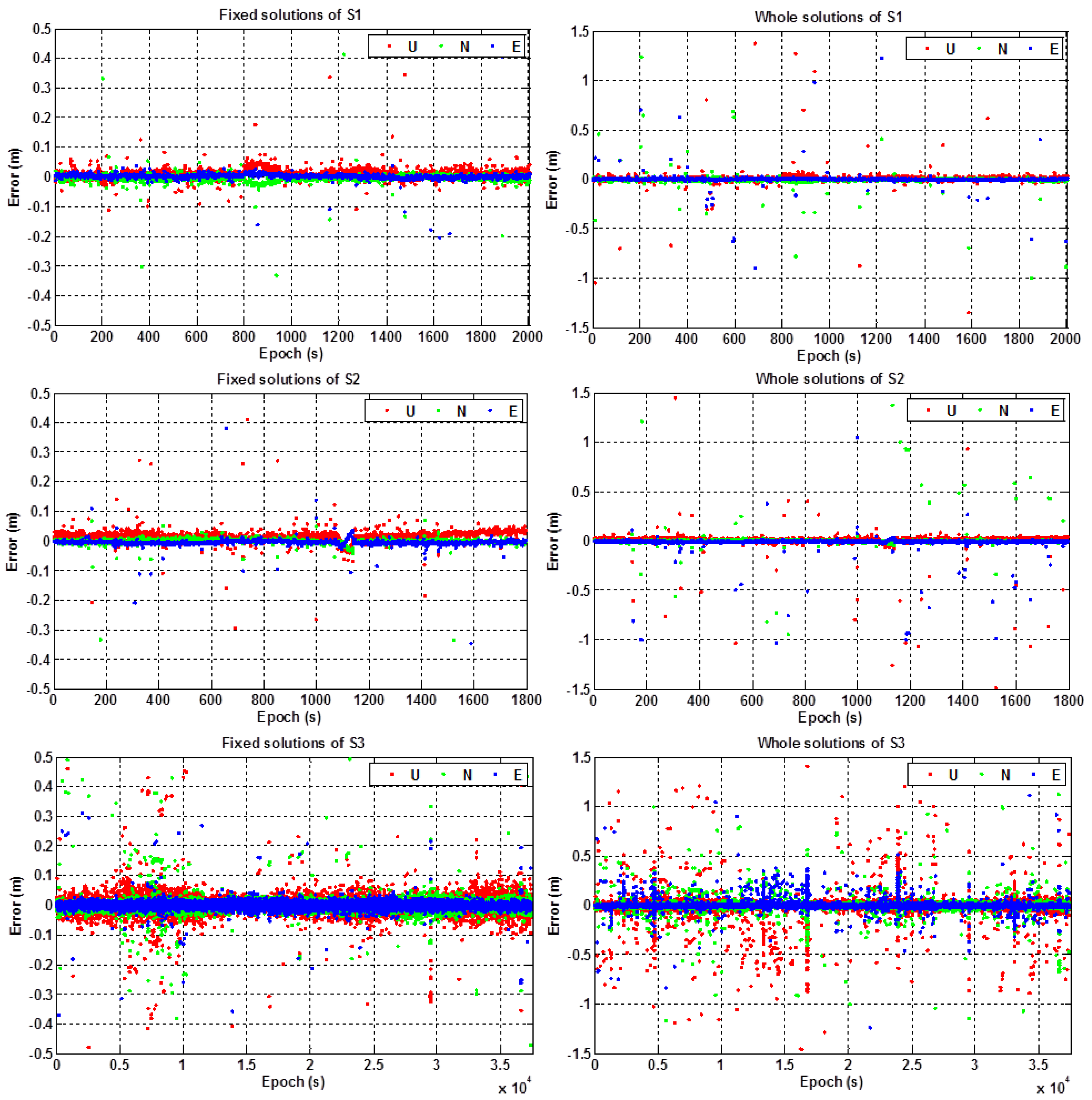
3.2.1. Static Test
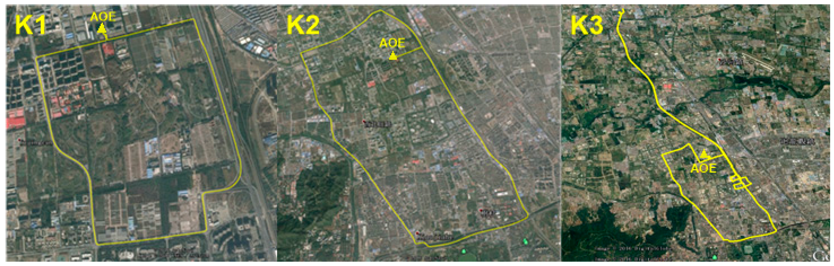
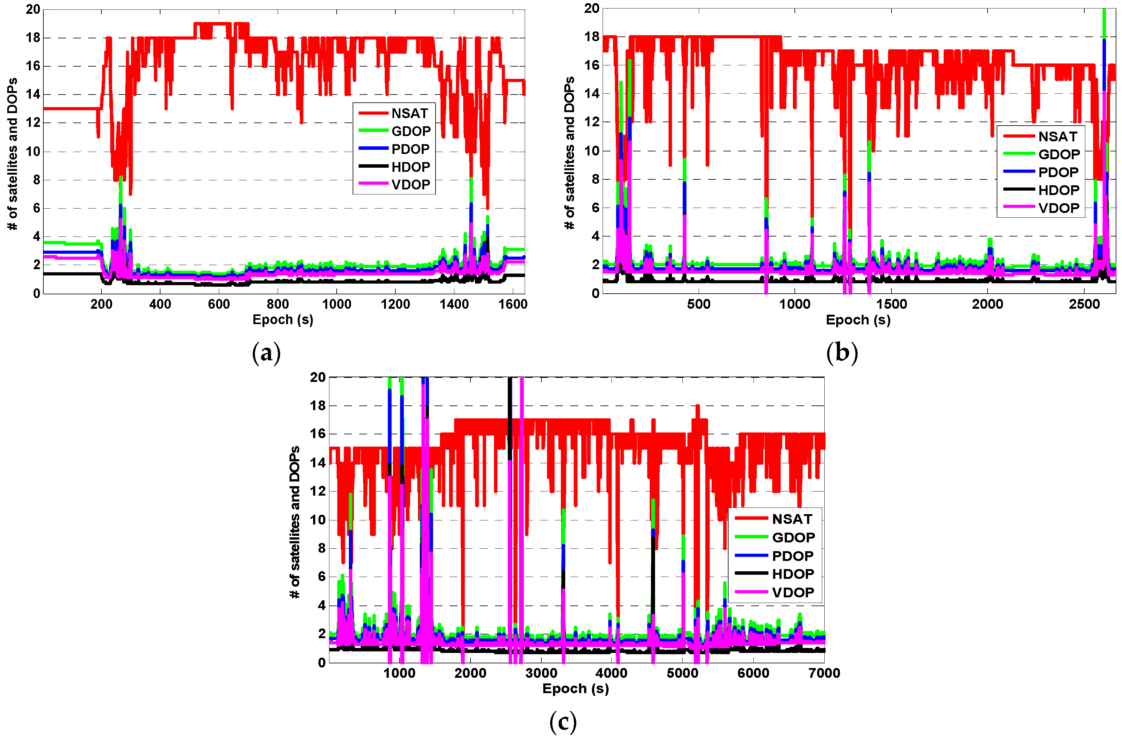
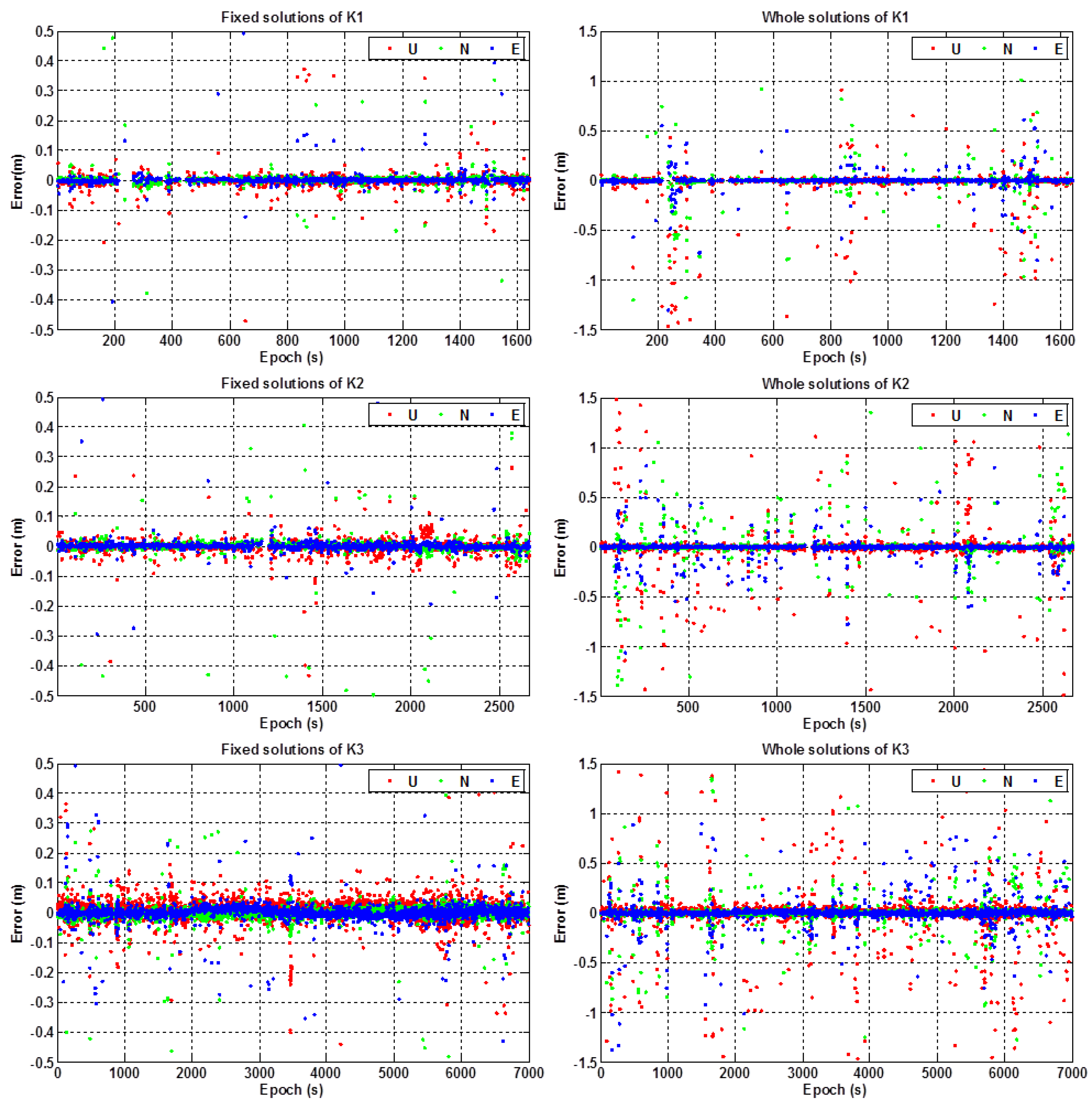
3.2.2. Kinematic Test
4. Conclusions
Acknowledgments
Author Contributions
Conflicts of Interest
References
- Fu, Y. The opportunities and challenges of applications in LBS for BeiDou navigation satellite system. Satell. Netw. 2014, 6, 28–32. (In Chinese) [Google Scholar]
- Yang, Y.; Li, J.; Xu, J.; Tang, J.; Guo, H.; He, H. Contribution of the compass satellite navigation system to global PNT users. Chin. Sci. Bull. 2011, 56, 2813–2819. [Google Scholar] [CrossRef]
- Odolinski, R.; Teunissen, P.; Odijk, D. Combined BDS, Galileo, QZSS and GPS single-frequency RTK. GPS Solut. 2015, 19, 151–163. [Google Scholar] [CrossRef]
- China Satellite Navigation Office (CSNO). BeiDou Navigation Satellite System Signal in Space Interface Control Document Open Service Signal (version 2.0); CSNO: Beijing, China, 2013. [Google Scholar]
- Yang, Y.; Li, J.; Wang, A.; Xu, J.; He, H.; Guo, H.; Shen, J.; Dai, X. Preliminary assessment of the navigation and positioning performance of BeiDou regional navigation satellite system. Sci. China Earth Sci. 2014, 57, 144–152. [Google Scholar] [CrossRef]
- Teunissen, P.; Odolinski, R.; Odijk, D. Instantaneous BeiDou + GPS RTK positioning with high cut-off elevation angles. J. Geod. 2014, 88, 335–350. [Google Scholar] [CrossRef]
- Odolinski, R.; Teunissen, P. Single-frequency, dual-GNSS versus dual-frequency, single-GNSS: A low-cost and high-grade receivers GPS-BDS RTK analysis. J. Geod. 2016, 90, 1255–1278. [Google Scholar] [CrossRef]
- Wang, L.; Wen, X.; Huang, C. Application of low cost GPS/BDS receiver in UAV precise navigation and positioning. In China Satellite Navigation Conference (CSNC) 2016 Proceedings: Volume I; Springer: Singapore, 2016; pp. 165–174. [Google Scholar]
- Mongrédien, C.; Doyen, J.; Ström, M.; Ammann, D. Centimeter-level positioning for UAVs and other mass-market applications. In Proceedings of the ION GNSS, Portland, OR, USA, 12–16 September 2016.
- Stempfhuber, W.; Buchholz, M. A precise, low-cost RTK GNSS system for UAV applications. In Proceedings of the International Conference on Unmanned Aerial Vehicle in Geomatics, Zurich, Switzerland, 14–16 September 2012.
- Ji, S.; Gao, Z.; Wang, W. M-DGPS: Mobile devices supported differential global positioning system algorithm. Arab. J. Geosci. 2015, 8, 6667–6675. [Google Scholar] [CrossRef]
- Guo, C.; Guo, W.; Cao, G.; Dong, H. A lane-level LBS system for vehicle network with high-precision BDS/GPS positioning. Comput. Intell. Neurosci. 2015, 2015, 531321. [Google Scholar] [CrossRef] [PubMed]
- BeiDou’s Ground-Based Augmentation System Started Its Operation. Available online: http://www.beidou.gov.cn/2016/05/19/20160519a0a2567105fb4614baa1b3747848d743.html (accessed on 6 December 2016). (In Chinese)
- Wang, L.; Li, Z.; Yuan, H.; Zhou, K. Validation and analysis of the performance of dual-frequency single-epoch BDS/GPS/GLONASS relative positioning. Chin. Sci. Bull. 2015, 60, 857–868. (In Chinese) [Google Scholar] [CrossRef]
- He, H.; Li, J.; Yang, Y.; Xu, J.; Guo, H.; Wang, A. Performance assessment of single- and dual-frequency BeiDou/GPS single-epoch kinematic positioning. GPS Solut. 2014, 18, 393–403. [Google Scholar] [CrossRef]
- Carcanague, S. Low-Cost GPS/GLONASS Precise Positioning Algorithm in Constrained Environment; Institut National Polytechnique de Toulouse: Toulouse, France, 2013. [Google Scholar]
- Wang, L.; Li, Z.; Yuan, H.; Zhou, K. Assessment and comparison of typical BeiDou navigation- and surveying-type terminals on single-epoch positioning performance. Satell. Navig. 2015, 3, 34–40. (In Chinese) [Google Scholar]
- Wübbena, G.; Schmitz, M.; Bagge, A. PPP-RTK: Precise point positioning using state-space representation in RTK networks. In Proceedings of the 18th International Technical Meeting of the Satellite Division of the Institute of Navigation, Long Beach, CA, USA, 13–16 September 2005; pp. 2584–2594.
- Collins, P. Isolating and estimating undifferenced GPS integer ambiguities. In Proceedings of the 2008 National Technical Meeting of the Institute of Navigation, San Diego, CA, USA, 28–30 January 2008; pp. 720–732.
- Ge, M.; Gendt, G.; Rothacher, M.; Shi, C.; Liu, J. Resolution of GPS carrier-phase ambiguities in precise point positioning (PPP) with daily observations. J. Geod. 2008, 82, 389–399. [Google Scholar] [CrossRef]
- Laurichesse, D.; Mercier, F.; Berthias, J.; Broca, P.; Cerri, L. Integer ambiguity resolution on undifferenced GPS phase measurements and its application to PPP and satellite precise orbit determination. Navigation 2009, 56, 135–149. [Google Scholar] [CrossRef]
- Geng, J.; Meng, X.; Dodson, A.; Teferle, F. Integer ambiguity resolution in precise point positioning: Method comparison. J. Geod. 2010, 84, 569–581. [Google Scholar] [CrossRef]
- Teunissen, P.; Khodabandeh, A. Review and principles of PPP-RTK methods. J. Geod. 2015, 89, 217–240. [Google Scholar] [CrossRef]
- Odijk, D.; Zhang, B.; Khodabandeh, A.; Odolinski, R.; Teunissen, P. On the estimability of parameters in undifferenced, uncombined GNSS network and PPP-RTK user models by means of S-system theory. J. Geod. 2015, 90, 15–44. [Google Scholar] [CrossRef]
- Wang, L.; Li, Z.; Yuan, H.; Zhao, J.; Zhou, K. Research and implementation on BDS/GNSS real-time positioning for urban high-precision location-based services. In China Satellite Navigation Conference (CSNC) 2016 Proceedings: Volume I; Springer: Singapore, 2016; pp. 277–286. [Google Scholar]
- Deng, C.; Tang, W.; Liu, J.; Shi, C. Reliable single-epoch ambiguity resolution for short baselines using combined GPS/BeiDou system. GPS Solut. 2014, 18, 375–386. [Google Scholar] [CrossRef]
- Teunissen, P.; Kleusberg, A. GPS for Geodesy, 2nd ed.; Springer: Berlin/Heidelberg, Germany, 1998. [Google Scholar]
- King, R.; Bock, Y. Documentation for the GAMIT GPS Analysis Software; Massachusetts Institute of Technology: Cambridge, MA, USA, 1999. [Google Scholar]
- Teunissen, P. The least-squares ambiguity decorrelation adjustment: A method for fast GPS integer ambiguity estimation. J. Geod. 1995, 70, 65–82. [Google Scholar] [CrossRef]
- Chang, X.; Yang, X.; Zhou, T. MLAMBDA: A modified LAMBDA method for integer least-squares estimation. J. Geod. 2005, 79, 552–565. [Google Scholar] [CrossRef]
- Teunissen, P. GNSS integer ambiguity validation: Overview of theory and methods. In Proceedings of the Institute of Navigation Pacific PNT, Honolulu, HI, USA, 23–25 April 2013; pp. 673–684.
- Teunissen, P.; Verhagen, S. The GNSS ambiguity ratio-test revisited: A better way of using it. Surv. Rev. 2009, 41, 138–151. [Google Scholar]
- Verhagen, S.; Teunissen, P. The ratio test for future GNSS ambiguity resolution. GPS Solut. 2012, 17, 535–548. [Google Scholar] [CrossRef]
- Li, L.; Li, Z.; Yuan, H.; Wang, L.; Hou, Y. Integrity monitoring-based ratio test for GNSS integer ambiguity validation. GPS Solut. 2016, 20, 573–585. [Google Scholar] [CrossRef]
- Wang, L.; Verhagen, S. A new ambiguity acceptance test threshold determination method with controllable failure rate. J. Geod. 2014, 89, 361–375. [Google Scholar] [CrossRef]
- Hou, Y.; Verhagen, S.; Wu, J. An efficient implementation of fixed failure-rate ratio test for GNSS ambiguity resolution. Sensors 2016, 16, 945. [Google Scholar] [CrossRef] [PubMed]
- Li, J.; Yang, Y.; Xu, J.; He, H.; Guo, H.; Wang, A. Performance analysis of single-epoch dual-frequency RTK by BeiDou navigation satellite system. In China Satellite Navigation Conference (CSNC) 2013 Proceedings; Springer: Berlin/Heidelberg, Germany, 2013; pp. 133–143. [Google Scholar]
- Wang, L.; Li, Z.; Yuan, H.; Zhao, J.; Zhou, K.; Yuan, C. Influence of the time-delay of correction for BDS and GPS combined real-time differential positioning. Electron. Lett. 2016, 52, 1063–1065. [Google Scholar] [CrossRef]
- Xu, Y.; Li, Q.; Xie, S.; Zhang, L. Study on algorithm and communication protocol of differential GPS positioning based on pseudorange. In Proceedings of the International Forum on Information Technology and Applications, Chengdu, China, 15–17 May 2009; pp. 606–609.


| Validation Approaches | Latency Time of Corrections (s) | Ambiguity Fixed-Rate (%) | RMS Error (cm) | ||
|---|---|---|---|---|---|
| Fixed Solutions | Unfixed Solutions | Whole Solutions | |||
| Traditional RT with fixed threshold (=2.0) | 0 | 96.9 | 1.5 | 40.7 | 9.0 |
| 5 | 95.5 | 1.7 | 46.7 | 10.2 | |
| 10 | 91.0 | 2.0 | 50.8 | 12.4 | |
| FF-RT with tolerable failure-rate (=0.01) | 0 | 100 | 1.7 | — | 1.7 |
| 5 | 99.8 | 4.3 | 36.8 | 6.1 | |
| 10 | 99.7 | 5.3 | 38.4 | 8.2 | |
| Experiments | Ambiguity Fixed-Rate (%) | RMS (m) | |||||
|---|---|---|---|---|---|---|---|
| Fixed Solutions | Unfixed Solutions | Whole Solutions | |||||
| H | V | H | V | H | V | ||
| S1 | 97.8 | 0.03 | 0.04 | 0.45 | 1.24 | 0.14 | 0.25 |
| S2 | 98.1 | 0.02 | 0.04 | 0.67 | 0.84 | 0.15 | 0.21 |
| S3 | 95.7 | 0.02 | 0.03 | 0.25 | 0.43 | 0.07 | 0.09 |
| Experiments | Error ≤ 0.1 m (%) | Error ≤ 0.2 m (%) | Error ≤ 0.5 m (%) | Error ≤ 1.0 m (%) | Error > 1.0 m (%) | |||||
|---|---|---|---|---|---|---|---|---|---|---|
| H | V | H | V | H | V | H | V | H | V | |
| S1 | 98.26 | 98.10 | 98.57 | 98.46 | 99.13 | 98.72 | 99.54 | 99.03 | 0.46 | 0.97 |
| S2 | 97.59 | 97.30 | 98.05 | 97.70 | 98.39 | 98.45 | 99.14 | 99.02 | 0.86 | 0.98 |
| S3 | 97.69 | 97.61 | 98.56 | 98.11 | 99.22 | 98.97 | 99.51 | 99.40 | 0.49 | 0.61 |
| Experiments | Ambiguity Fixed-Rate (%) | RMS (m) | |||||
|---|---|---|---|---|---|---|---|
| Fixed Solutions | Unfixed Solutions | Whole Solutions | |||||
| H | V | H | V | H | V | ||
| K1 | 92.4 | 0.08 | 0.12 | 1.07 | 1.25 | 0.24 | 0.40 |
| K2 | 90.6 | 0.09 | 0.13 | 1.15 | 1.78 | 0.28 | 0.47 |
| K3 | 93.5 | 0.11 | 0.14 | 1.23 | 1.42 | 0.32 | 0.45 |
| Experiments | Error ≤ 0.1 m (%) | Error ≤ 0.2 m (%) | Error ≤ 0.5 m (%) | Error ≤ 1.0 m (%) | Error > 1.0 m (%) | |||||
|---|---|---|---|---|---|---|---|---|---|---|
| H | V | H | V | H | V | H | V | H | V | |
| K1 | 80.30 | 80.75 | 85.51 | 84.61 | 93.50 | 90.41 | 97.30 | 94.53 | 2.70 | 5.47 |
| K2 | 85.42 | 85.66 | 86.98 | 87.46 | 92.53 | 90.80 | 96.67 | 94.09 | 3.33 | 5.91 |
| K3 | 93.35 | 92.54 | 94.51 | 94.01 | 96.92 | 95.84 | 98.19 | 97.47 | 1.81 | 2.53 |
© 2016 by the authors; licensee MDPI, Basel, Switzerland. This article is an open access article distributed under the terms and conditions of the Creative Commons Attribution (CC-BY) license (http://creativecommons.org/licenses/by/4.0/).
Share and Cite
Wang, L.; Li, Z.; Zhao, J.; Zhou, K.; Wang, Z.; Yuan, H. Smart Device-Supported BDS/GNSS Real-Time Kinematic Positioning for Sub-Meter-Level Accuracy in Urban Location-Based Services. Sensors 2016, 16, 2201. https://doi.org/10.3390/s16122201
Wang L, Li Z, Zhao J, Zhou K, Wang Z, Yuan H. Smart Device-Supported BDS/GNSS Real-Time Kinematic Positioning for Sub-Meter-Level Accuracy in Urban Location-Based Services. Sensors. 2016; 16(12):2201. https://doi.org/10.3390/s16122201
Chicago/Turabian StyleWang, Liang, Zishen Li, Jiaojiao Zhao, Kai Zhou, Zhiyu Wang, and Hong Yuan. 2016. "Smart Device-Supported BDS/GNSS Real-Time Kinematic Positioning for Sub-Meter-Level Accuracy in Urban Location-Based Services" Sensors 16, no. 12: 2201. https://doi.org/10.3390/s16122201