
MEMS and FOG Technologies for Tactical and Navigation Grade Inertial Sensors—Recent Improvements and Comparison

Abstract
:1. Introduction
2. MEMS Accelerometers
2.1. Background
2.2. Theoretical Analysis
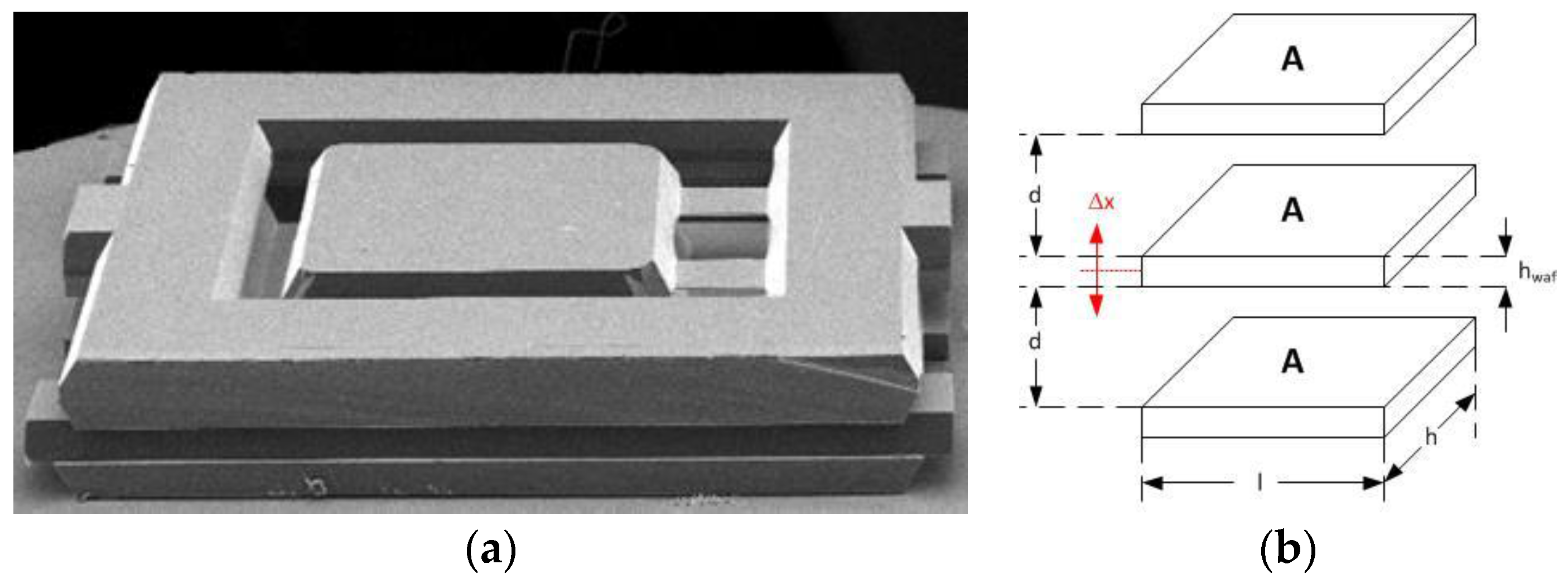
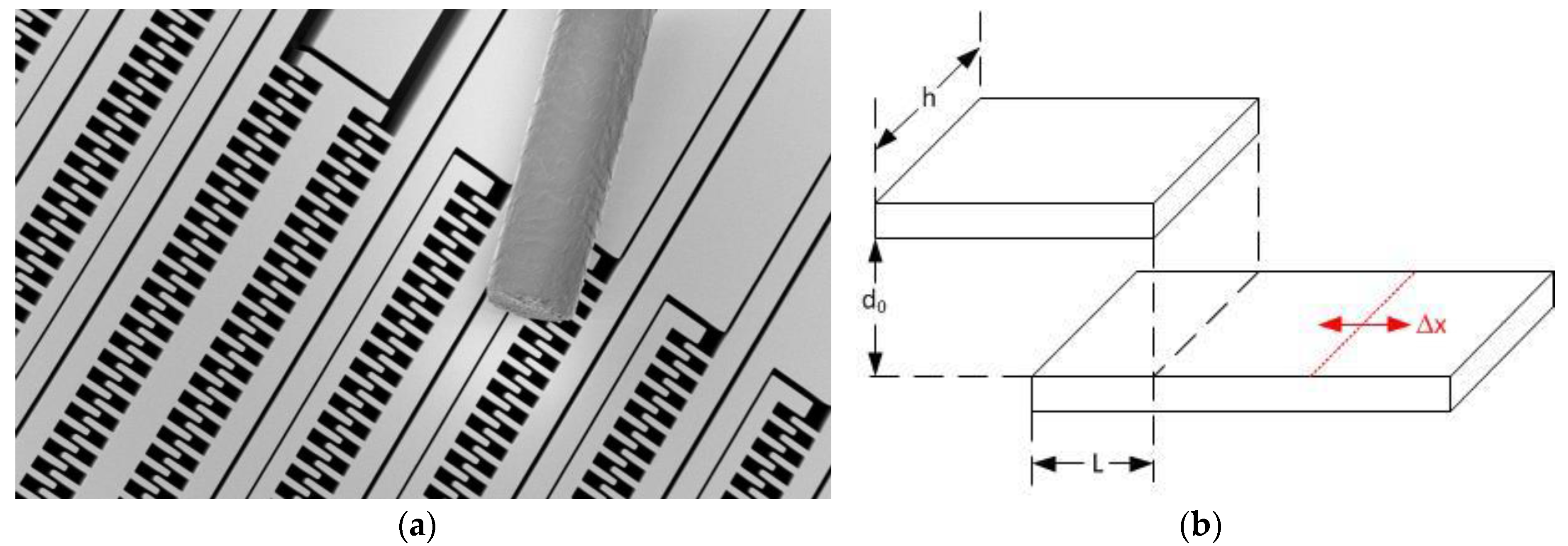
2.2.1. Electrode Design: Geometrical Sensitivity
2.2.2. Spring Design and Displacement vs. Acceleration
2.2.3. Forces: Linearity
2.2.4. Damping, Noise, and Bandwidth
2.3. Production Data
2.3.1. Scalefactor Residual Error
2.3.2. Bias and Bias Residual Error
2.3.3. Vibration Rectification Error
2.4. Summary and Outlook
- The excellent behavior of the current lateral design in heavy vibration environments will be improved by further increasing the bandwidth of the accelerometer while the force independency of the design will be maintained.
- The acceleration sensitivity of the MEMS chip shall be increased to improve the bias stability of the system. This can be achieved by either a chip redesign or by electrostatic manipulation of the accelerometer’s spring constant. While the former concept is a more general task to be performed as an iteration of the current MEMS chip design, the latter can be applied already on existing chip designs.
3. MEMS Gyroscopes
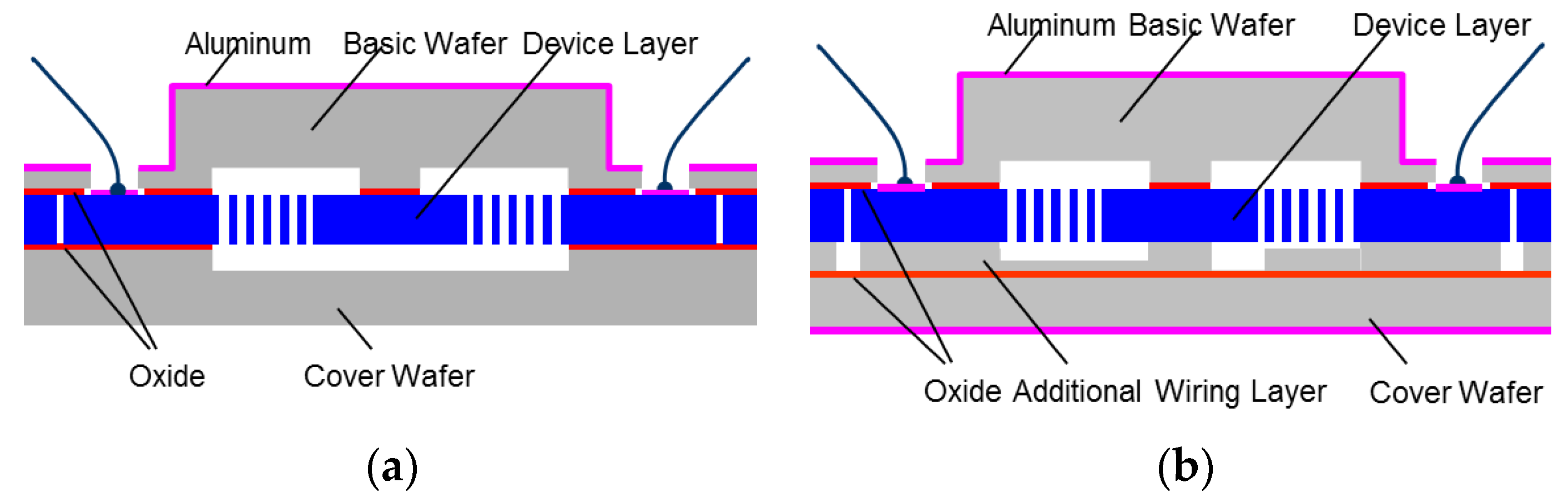
3.1. Technology
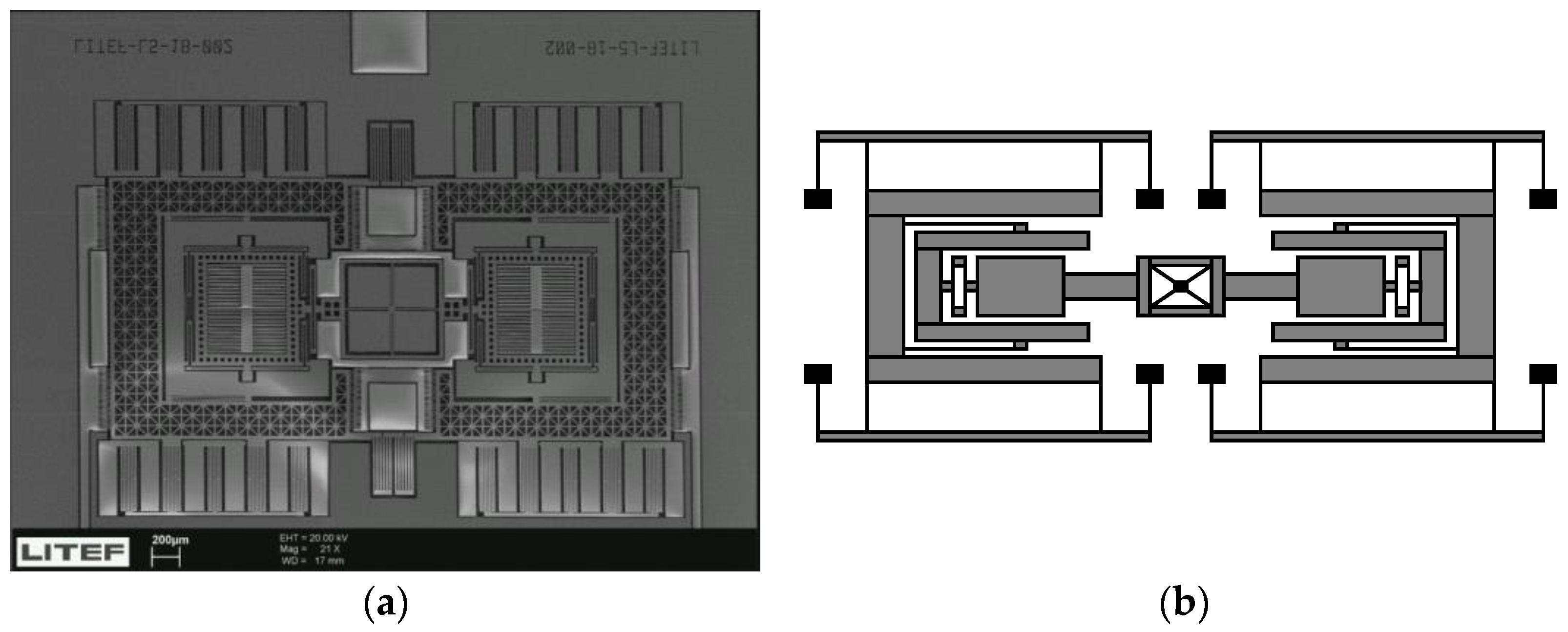
3.2. Gyroscope Chip Design
3.3. Operating Principles
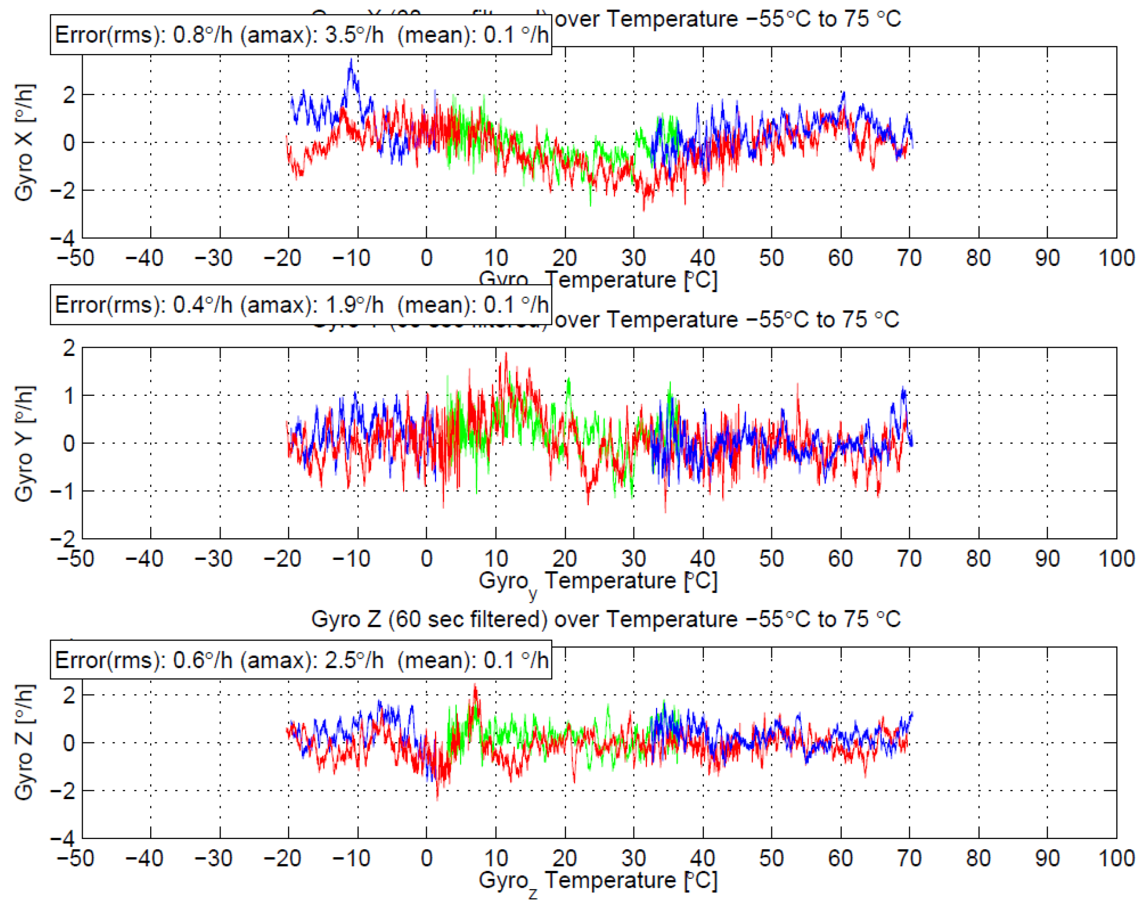
3.4. Performance and Outlook
4. Fiber Optic Gyros
4.1. Background
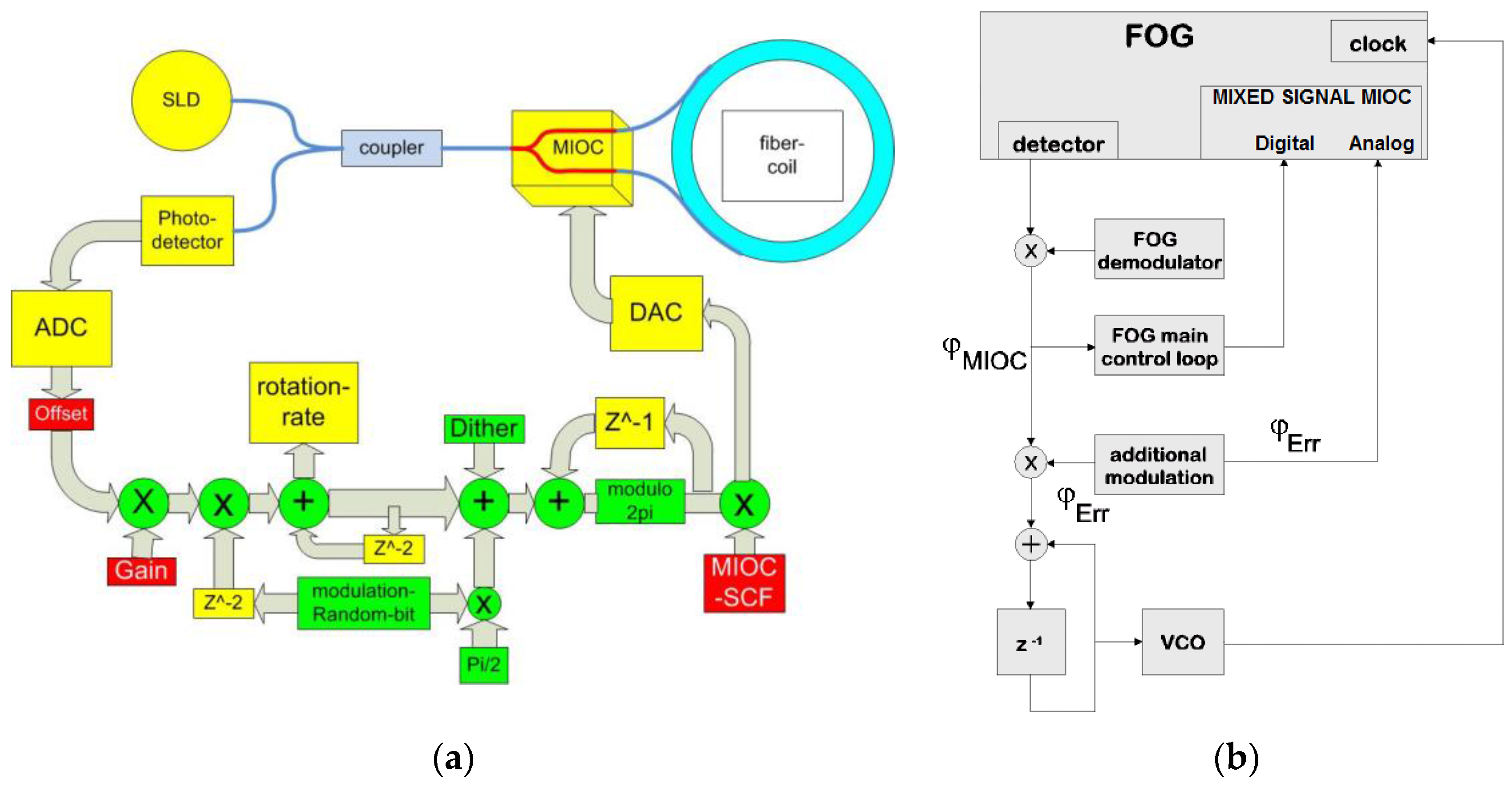
4.2. Random Modulation and MIOCs with Phase Bleed in the FOG
4.3. Approach with DC-Free Modulation
4.3.1. Preliminary Considerations
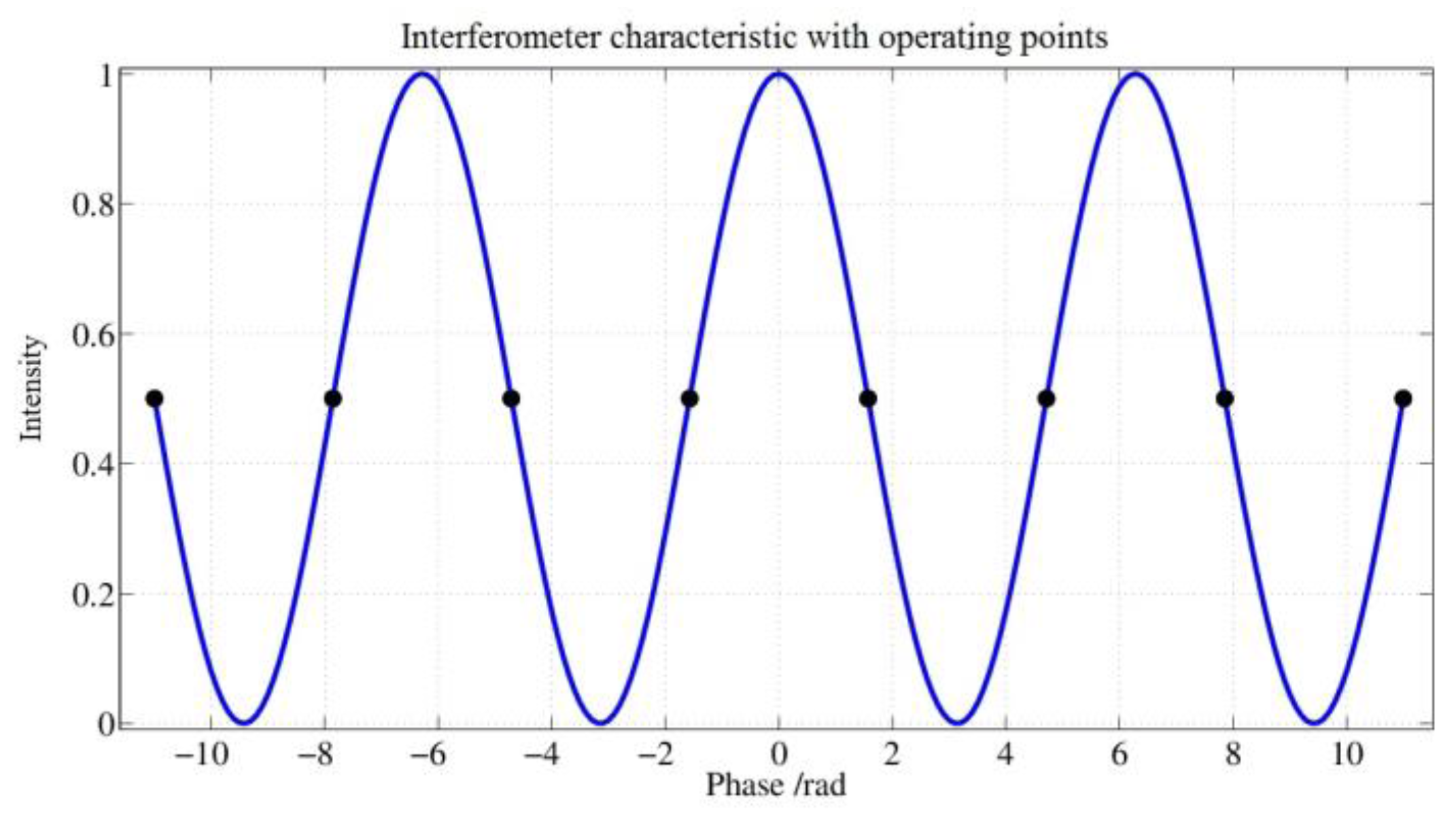
- Without modulation, the peak of the interferometer characteristic would be steered where the slope is zero. Thus, the sensitivity of the sensor is also zero and there would be no directional information present. To avoid these disadvantages, the control uses points that lie where the slope is greatest.
- If only points with the same sign were controlled, an applied rotation rate would lead to a DC voltage signal at the photodetector, which would be suppressed by the subsequent circuit stages. Therefore, work points with changing signs are controlled. This results in a modulation of the detector signal so that the signal lies in the transmission range of the following amplifier stages.
- If the control of the working points alternates periodically between positive and negative slopes, the drive signal at the MIOC would correlate with the demodulator reference of the detector signal. This results in an insensitivity in the sensor for small rotation rates. Therefore, the sequence of the signs of the slope at the operating points have to be chosen in a way that the mentioned correlation disappears.
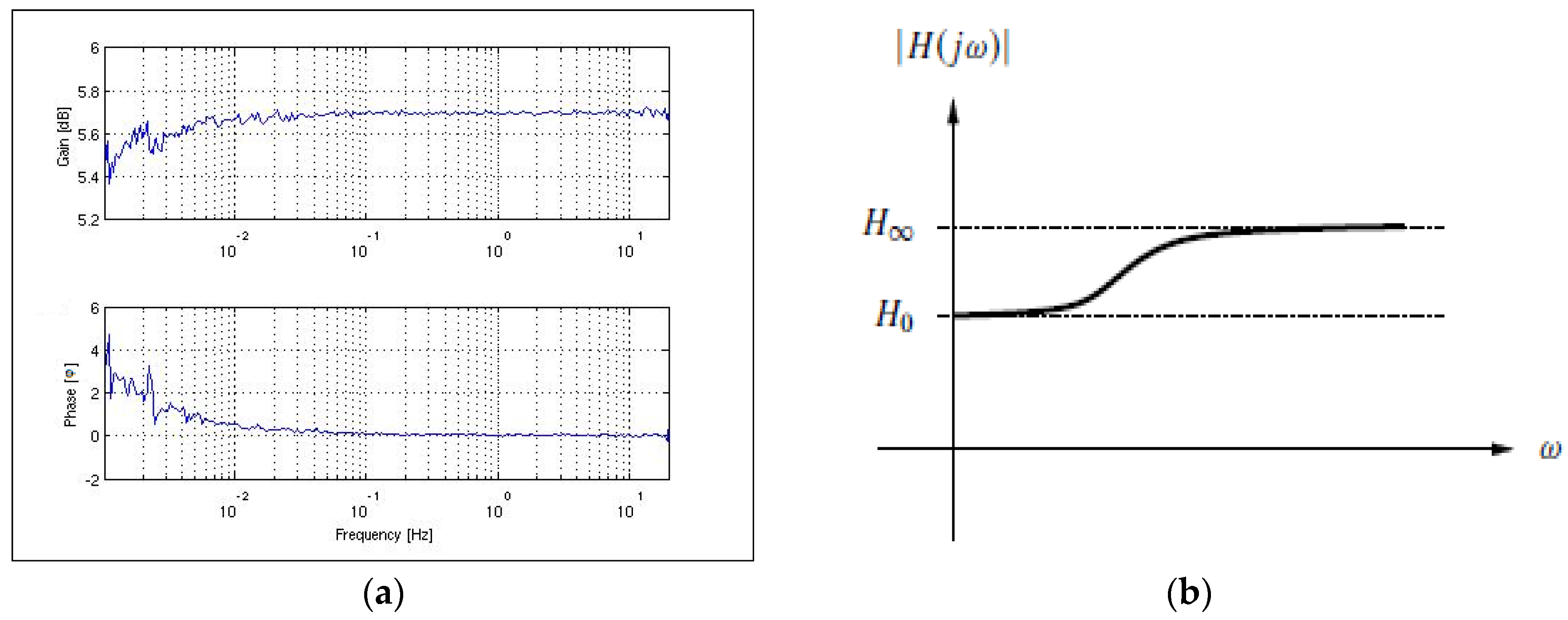
- The modulation must be such that a stable operation of the scale factor controller (auxiliary control loop) can be ensured for any input rotation rates of the sensor.
- 5.
- The modulation must be such that the expected value of the MIOC drive signal becomes zero.
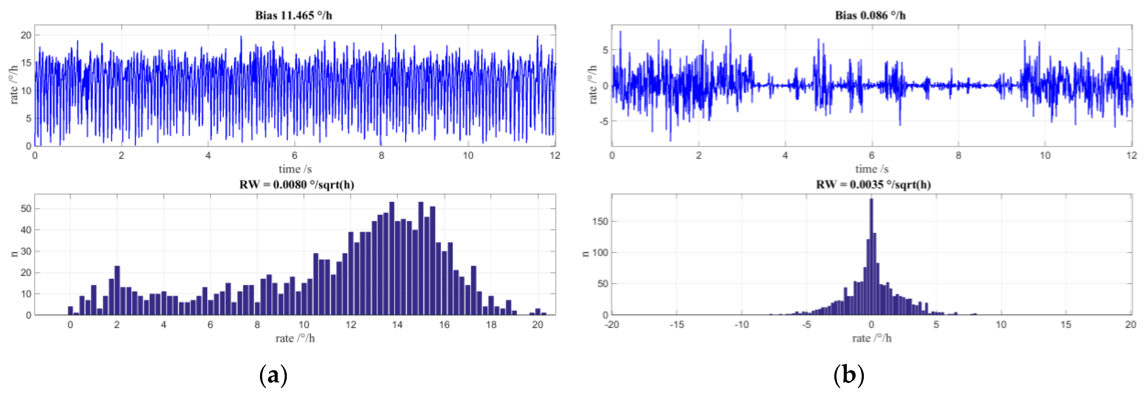
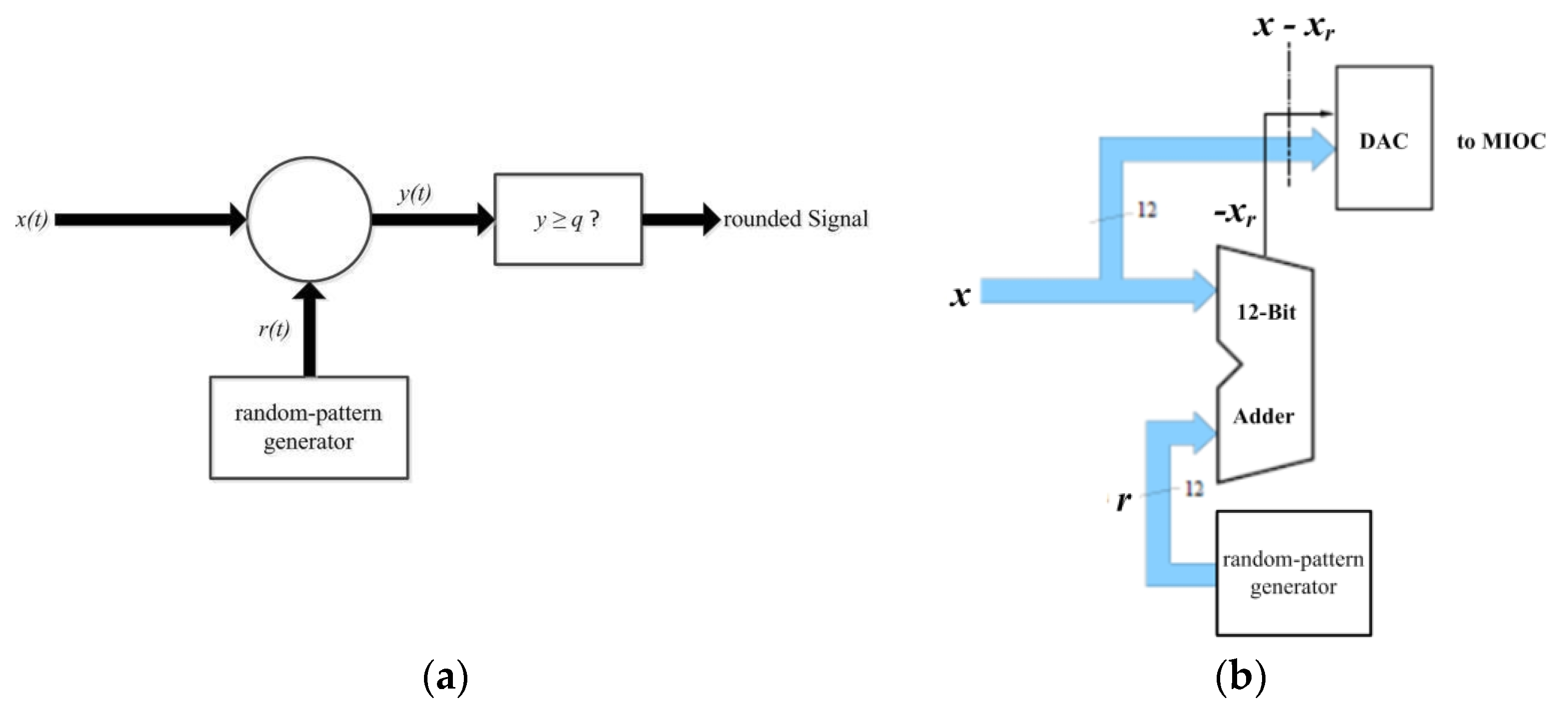
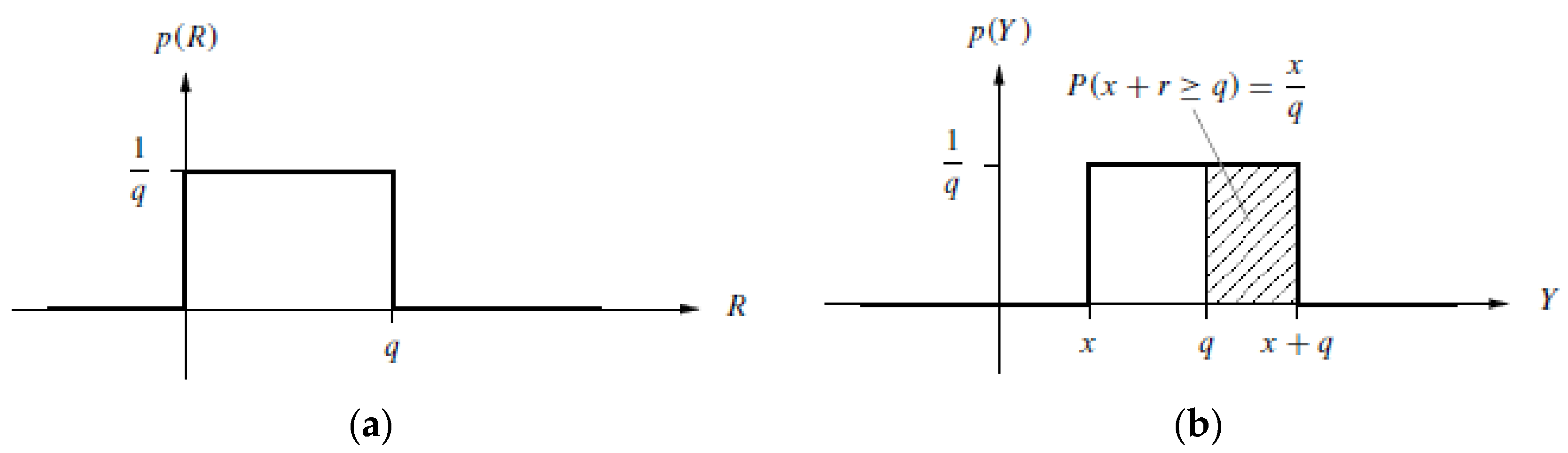
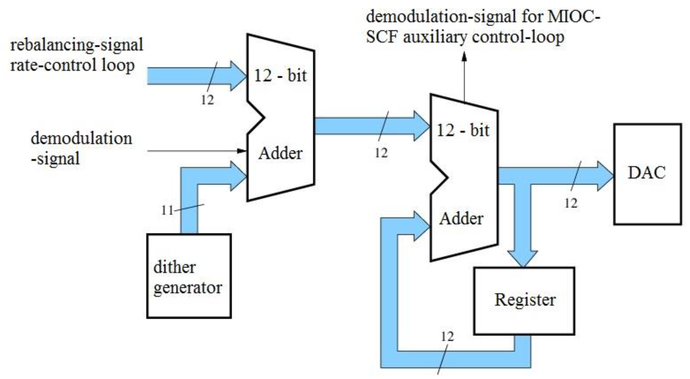
4.3.2. Statistical Rounding
- q = π which results in a modulation range of the MIOC of 2π (henceforth referred to as 2π-modulation).
- q = 2π which results in a modulation range of the MIOC of 4π (henceforth referred to as 4π-modulation).
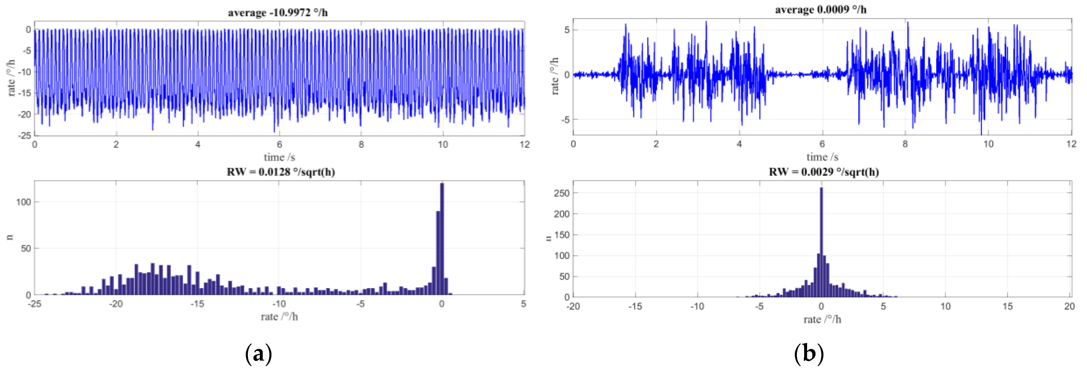
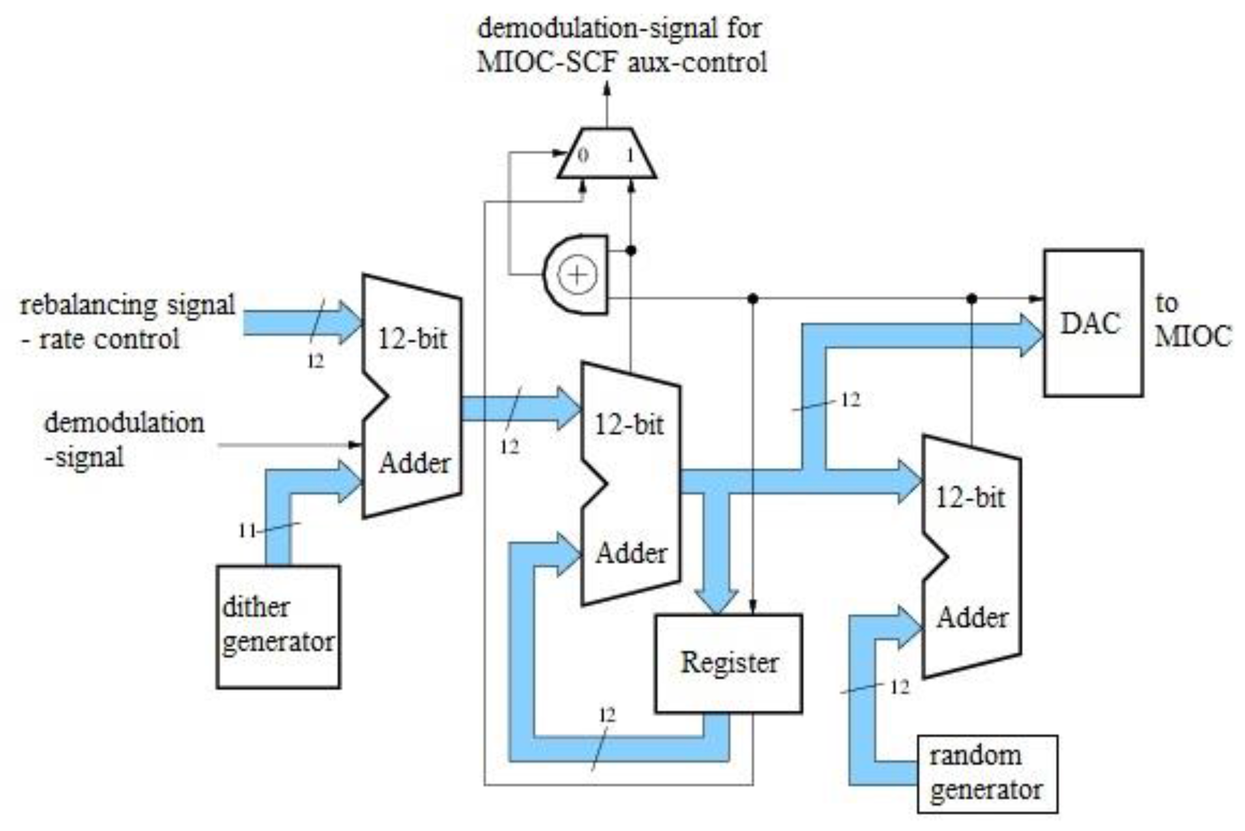
4.3.3. Mean-Value-Free MIOC Control with 4π-Modulation
4.4. Discussion and Outlook
5. Comparison of Fiber Optic and MEMS Gyroscopes
6. Conclusions
Author Contributions
Conflicts of Interest
References
- Curey, R.K.; Ash, M.E.; Thielman, L.O.; Barker, C.H. Proposed IEEE Inertial Systems Terminology Standard and Other Inertial Sensor Standards. In Proceedings of the Position Location Navigation Symposium (PLANS 2004), Monterey, CA, USA, 26–29 April 2004.
- IEEE Std 528-2001. IEEE Standard for Inertial Sensor Terminology; The Institute of Electrical and Electronics Engineers, Inc.: New York, NY, USA.
- Strachan, V.F. Inertial Measurement Technology in the Satellite Navigation Environment. J. Navig. 2000, 53, 247–260. [Google Scholar] [CrossRef]
- Probst, U. Measurement-While-Drilling System Based on Inertial Sensors for Guided Drilling and Resurveying Applications. In Proceedings of the Inertial Sensors and Systems 2013 (DGON ISS), Karlsruhe, Germany, 17–18 September 2013.
- Martin, T.; Probst, U.; Fischer, H.; Straub-Kalthoff, J.; Herbert, U. Simulation Tool Chain for Multi-Sensor Navigation Filters. In Proceedings of the Inertial Sensors and Systems 2014 (DGON ISS), Karlsruhe, Germany, 16–17 September 2014.
- Lefevre, H. The Fiber-Optic Gyroscope, 2nd ed.; Artech House: Boston, MA, USA, 2014. [Google Scholar]
- Lärmer, F. Method of Anisotropically Etching Silicon. U.S. Patent 5,501,893, 26 March 1996. [Google Scholar]
- Breng, U.; Gutmann, W.; Hafen, M.; Handrich, E.; Leiblich, M.; Ryrko, B.F.; Wetzel, M.; Zimmermann, S.; Billep, D.; Gessner, T.; et al. A Novel Micromachined Silicon Gyro. In Proceedings of the Symposium Gyro Technology 1998 (DGON SGT), Stuttgart, Germany, 15–16 September 1998.
- Xia, D.; Yu, C.; Kong, L. The Development of Micromachined Gyroscope Structure and Circuitry Technology. Sensors 2014, 14, 1394–1473. [Google Scholar] [CrossRef] [PubMed]
- Kemmler, M.W.; Spahlinger, G.; Kunz, J.; Ribes, M.; Zimmermann, S. Design of a commercial small-volume fiber optic gyro. In Proceedings of the SPIE Fiber Optic Gyros: 20th Anniversary Conference, Denver, CO, USA, 4 August 1996; Volume 2837, pp. 92–97.
- Kunz, J.; Kemmler, M.W.; Spahlinger, G.; Ribes, M. Design of an ASIC for a commercial small-volume fiber optic gyro. In Proceedings of the SPIE Fiber Optic Gyros: 20th Anniversary Conference, Denver, CO, USA, 4 August 1996; Volume 2837, pp. 98–105.
- Ribes, M.; Spahlinger, G.; Kemmler, M.W. 0.1 deg/h DSP-Controlled Fiber Optic Gyroscope. In Proceedings of the SPIE Fiber Optic Gyros: 20th Anniversary Conference, Denver, CO, USA, 4 August 1996; Volume 2837, pp. 199–206.
- Spahlinger, G.; Kemmler, M.W.; Ruf, M.; Ribes, M.; Zimmermann, S. Error Compensation via Signal Correlation in High Precision Closed-Loop Fiber Optic Gyros. In Proceedings of the SPIE Fiber Optic Gyros: 20th Anniversary Conference, Denver, CO, USA, 4 August 1996; Volume 2837, pp. 218–227.
- Deppe-Reibold, O.; Böhler, H.; Dorner, G.; Hafen, M.; Rasch, A.; Spahlinger, G. Prototype Study of a High Performance Inertial Measurement Unit for Use in Inertial Navigation Applications based on NG LITEFs AHRS LCR-100. In Proceeding of the Symposium Gyro Technology 2009 (DGON SGT), Karlsruhe, Germany, 22–23 September 2009.
- B-290 Triad Three Axis Accelerometer Datasheet; Northrop Grumman LITEF GmbH: Freiburg, Germany, 2011.
- Billep, D.; Hiller, K.; Froemel, J.; Tenholte, D.; Reuter, D.; Doetzel, W.; Gessner, T. Post-processing gap reduction in a micromachined resonator for vacuum pressure measurement. In Proceedings of the SPIE Smart Sensors, Actuators, and MEMS II, 341, Sevilla, 1 July 2005; Volume 5836.
- König, S.; Leinfelder, P. First results with MEMS tilt sensors on bridges. In Proceedings of the Inertial Sensors and Systems 2016 (DGON ISS), Karlsruhe, Germany, 20–21 September 2016.
- Föllinger, O. Lineare Abtastsysteme, 3rd ed.; R. Oldenbourg Verlag: Munich, Germany, 1986. [Google Scholar]
- IEEE Std 1293-1998. IEEE Standard Specification Format Guide and Test Procedure for Linear, Single-Axis, Nongyroscopic Accelerometers; The Institute of Electrical and Electronics Engineers, Inc.: New York, NY, USA, 1998. [Google Scholar]
- LCR-100 Gyrocompass AHRS Datasheet; Northrop Grumman LITEF GmbH: Freiburg, Germany, 2012.
- Geiger, W.; Breng, U. Method for the Production of a Component, and Component. U.S. Patent 8,258,590, 4 September 2012. [Google Scholar]
- Hiller, K.; Hahn, S.; Küchler, M.; Billep, D.; Forke, R.; Geßner, T.; Köhler, D.; Konietzka, S.; Pohle, A. Erweiterungen und Anwendungen der BDRIE-Technologie zur Herstellung hermetisch gekapselter Sensoren mit hoher Güte. In Proceedings of the Mikrosystemtechnik 2013, Aachen, Germany, 14–16 October 2013.
- Geiger, W.; Leinfelder, P.; Spahlinger, G.; Bartholomeyczik, J. Rotation rate sensor. U.S. Patent 8,365,595, 5 February 2013. [Google Scholar]
- Geiger, W. Coriolis Gyro. U.S. Patent 8,342,023, 1 January 2013. [Google Scholar]
- Trusov, A.A.; Rozelle, D.M.; Atikyan, G.; Zotov, S.A.; Simon, B.R.; Shkel, A.M.; Meyer, A.D. Non-Axisymmetric Coriolis Vibratory Gyroscope with Whole Angle, Force Rebalance, and Self-Calibration. In Proceedings of the Technical Digest of IEEE Solid State Sensors, Actuators and Microsystems Workshop, Hilton Head Island, SC, USA, 8–12 June 2014.
- Lynch, D.D. Coriolis Vibratory Gyros. In Proceedings of the Symposium Gyro Technology 1998 (DGON SGT), Stuttgart, Germany, 15–16 September 1998.
- Tronics and Si-Ware Systems Partners in Developing MEMS Gyro Sensors. Available online: http://www.tronicsgroup.com/Tronics-and-Si-Ware-Systems (accessed on 11 March 2017).
- Omar, A.; Elshennawy, A.; Ismail, A.; Nagib, M.; Elmala, M.; Elsayed, A. A New Versatile Hardware Platform for Closed-Loop Gyro Evaluation. In Proceedings of the Inertial Sensors and Systems 2015 (DGON ISS), Karlsruhe, Germany, 22–23 September 2015.
- Rombach, S.; Maurer, M.; Manoli, Y. Continuous-Time Lowpass and Bandpass ΔΣ-Modulators for Closed-Loop Readout Circuits of Capacitive MEMS Gyroscopes. In Proceedings of the Inertial Sensors and Systems 2015 (DGON ISS), Karlsruhe, Germany, 22–23 September 2015.
- Spahlinger, G. Operating Method for a Coriolis Gyro, and Evaluation/Control Electronics Which Are Suitable for This Purpose. U.S. Patent 7,805,993, 7 November 2005. [Google Scholar]
- Spahlinger, G. Method for Controlling/Regulating a Physical Quantity of a Dynamic System, in Particular a Micromechanical Sensor. U.S. Patent 7,490,015, 10 February 2009. [Google Scholar]
- Prikhodko, I.P.; Trusov, A.A.; Shkel, A.M. Compensation of drifts in high-Q MEMS gyroscopes using temperature self-sensing. Sens. Actuators A Phys. 2013, 201, 517–524. [Google Scholar] [CrossRef]
- Peters, C.; Gutmann, W.; Hafen, M.; Jäckle, A.; Kunz, J.; Ruf, M.; Stumpf, K.; Zimmermann, S.; Geiger, W. Results of Qualification and Initial Prototype Production of a MEMS IMU. In Proceedings of the Symposium Gyro Technology 2011 (DGON SGT), Karlsruhe, Germany, 20–21 September 2011.
- Rottschalk, M.; Rasch, A.; Karthe, W. Electrooptic Behavior of Proton Exchanged LiNbO3 Optical Waveguides. J. Opt. Commun. 1988, 9, 19–23. [Google Scholar] [CrossRef]
- Voigt, S. Electrooptical Digital Waveguide Modulator. U.S. Patent 9,329,412, 8 August 2013. [Google Scholar]
- Voigt, S.; Spahlinger, G.; Newzella, A. Digital Phase Modulator for a Fiber-Optic Device. U.S. Patent 7,469,075, 6 July 2006. [Google Scholar]
- Spahlinger, G.; Voigt, S. Method for Regulating the Operating Frequency and Multifunctional Integrated Circuit Chip for a Fiber-Optic Gyroscope. U.S. Patent 7,283,246, 16 October 2007. [Google Scholar]
- Bulmer, C.H.; Burns, W.K.; Hiser, S.C. Pyroelectric Effects in LiNbO3 channel waveguide devices. Appl. Phys. Lett. 1986, 48, 1036–1038. [Google Scholar] [CrossRef]
- Spahlinger, G. Fiber Optic Sagnac Interferometer with Digital Phase Ramp Resetting via Correlation-Free Demodulator Control. U.S. Patent 5,123,741, 23 June 1992. [Google Scholar]
- Graindorge, P.; Arditty, H.; Lefevre, H. Device for Measuring a Nonreciprocal Phase Shift Produced in a Closed-Loop Interferometer. U.S. Patent 4,705,399, 10 November 1987. [Google Scholar]
- Arditty, H.; Puech, C.; Papuchon, M. Device for Measuring a Phase Shift Which Is Not Reciprocal Produced in a Ring Interferometer. U.S. Patent 5,056,919, 15 October 1991. [Google Scholar]
- Lefevre, H.C. Integrated optics: A practical solution for the Fiber-Optic Gyroscope. In Proceedings of the SPIE Fiber Optic Gyros, 10th Anniversary Conference, Cambridge, MA, USA, 18 August 1986; Volume 719.
- Gröllmann, P. Fiber Optic Sagnac Interferometer with Digital Phase Ramp Resetting. U.S. Patent 5,116,127, 26 May 1992. [Google Scholar]
- Büschelberger, H.J.; Spahlinger, G. Fiber Optic Sagnac Interferometer with Digital Phase Ramp Resetting via Correlation-Free Demodulator Control. U.S. Patent 5,214,488, 25 May 1993. [Google Scholar]
- Spahlinger, G. Method and Apparatus for Stabilizing Control Loop Scale Factor and Gain in a Fiber Optic Sagnac Interferometer. U.S. Patent 5,351,123, 27 September 1994. [Google Scholar]
- Spahlinger, G. Suppression of limit-cycles in digital filters by statistical rounding. In Proceedings of the ISCAS-85, Kyoto, Japan, 5–7 June 1985.
- Shupe, D.M. Thermally induced nonreciprocity in the fiber-optic interferometer. Appl. Opt. 1980, 19, 654–655. [Google Scholar] [CrossRef] [PubMed]


| Accelerometer Design | Vertical | Lateral |
|---|---|---|
| Structuring | KOH—Wet etching | DRIE |
| Controller | PI | Dead-beat |
| Bandwidth | >400 Hz | >2 kHz |
| Damping | Torquer/Pickoff electrodes | Damping electrodes |
| Gas pressure | 13 mbar | 200 mbar |
| Parameter | Test Conditions | Typ. | Unit |
|---|---|---|---|
| Dynamic range | 1500 (max.) | °/s | |
| Scalefactor repeatability | −40 °C ≤ T ≤ 85 °C; 1σ | 300 | ppm |
| Bias repeatability | −40 °C ≤ T ≤ 85 °C; 1σ | 1.2 | °/h |
| Bias instability (Allan deviation) | 0.1 | °/h | |
| Angle random walk | 0.1 | °/√h | |
| Vibration rectification error | rms | 0.09 | °/h/g2 |
| −3 dB bandwidth | 240 | Hz |
| Parameter | Test Conditions | Typ. | Unit |
|---|---|---|---|
| Dynamic range | 1500 (max.) | °/s | |
| Scalefactor repeatability | −40 °C ≤ T ≤ 71 °C; 1σ | 30 | ppm |
| Bias repeatability | −40 °C ≤ T ≤ 71 °C; 1σ | 0.015 | °/h |
| Bias instability (Allan deviation) | 0.0012 | °/h | |
| Angle random walk | 0.005 | °/√h | |
| −3 dB bandwidth | 8000 | Hz |
© 2017 by the authors. Licensee MDPI, Basel, Switzerland. This article is an open access article distributed under the terms and conditions of the Creative Commons Attribution (CC BY) license ( http://creativecommons.org/licenses/by/4.0/).
Share and Cite
Deppe, O.; Dorner, G.; König, S.; Martin, T.; Voigt, S.; Zimmermann, S. MEMS and FOG Technologies for Tactical and Navigation Grade Inertial Sensors—Recent Improvements and Comparison. Sensors 2017, 17, 567. https://doi.org/10.3390/s17030567
Deppe O, Dorner G, König S, Martin T, Voigt S, Zimmermann S. MEMS and FOG Technologies for Tactical and Navigation Grade Inertial Sensors—Recent Improvements and Comparison. Sensors. 2017; 17(3):567. https://doi.org/10.3390/s17030567
Chicago/Turabian StyleDeppe, Olaf, Georg Dorner, Stefan König, Tim Martin, Sven Voigt, and Steffen Zimmermann. 2017. "MEMS and FOG Technologies for Tactical and Navigation Grade Inertial Sensors—Recent Improvements and Comparison" Sensors 17, no. 3: 567. https://doi.org/10.3390/s17030567