Counter-Based Broadcast Scheme Considering Reachability, Network Density, and Energy Efficiency for Wireless Sensor Networks


School of Electrical and Electronics Engineering, Chung-Ang University, 84 Heukseok-ro, Dongjak-gu, Seoul 06974, Korea
*
Author to whom correspondence should be addressed.
Sensors 2018, 18(1), 120; https://doi.org/10.3390/s18010120
Submission received: 16 November 2017
/
Revised: 20 December 2017
/
Accepted: 21 December 2017
/
Published: 4 January 2018
(This article belongs to the Special Issue QoS in Wireless Sensor Networks)
Abstract
:A wireless sensor network (WSN) is emerging as an innovative method for gathering information that will significantly improve the reliability and efficiency of infrastructure systems. Broadcast is a common method to disseminate information in WSNs. A variety of counter-based broadcast schemes have been proposed to mitigate the broadcast-storm problems, using the count threshold value and a random access delay. However, because of the limited propagation of the broadcast-message, there exists a trade-off in a sense that redundant retransmissions of the broadcast-message become low and energy efficiency of a node is enhanced, but reachability become low. Therefore, it is necessary to study an efficient counter-based broadcast scheme that can dynamically adjust the random access delay and count threshold value to ensure high reachability, low redundant of broadcast-messages, and low energy consumption of nodes. Thus, in this paper, we first measure the additional coverage provided by a node that receives the same broadcast-message from two neighbor nodes, in order to achieve high reachability with low redundant retransmissions of broadcast-messages. Second, we propose a new counter-based broadcast scheme considering the size of the additional coverage area, distance between the node and the broadcasting node, remaining battery of the node, and variations of the node density. Finally, we evaluate performance of the proposed scheme compared with the existing counter-based broadcast schemes. Simulation results show that the proposed scheme outperforms the existing schemes in terms of saved rebroadcasts, reachability, and total energy consumption.
1. Introduction
A wireless sensor network (WSN) is a network formed by a large number of sensor nodes, who detect the physical phenomena of the surrounding environments and report the sensed data to a sink node through multi-hop links. WSNs are regarded as an innovative method for gathering information that will significantly improve the reliability and efficiency of infrastructure systems such as smart grid, smart homes, smart industrial automation, etc. Broadcasting is a common method for disseminating information in a WSN, when a node intends to share its data efficiently among each other. When the source node transmits a broadcast-message, the receiving nodes retransmit this message to all other nodes in their transmission range, and, thus, information exchange is possible between nodes in a multi-hop distance [1,2]. Flooding, in which each node retransmits every uniquely received broadcast-message exactly once, is the simplest broadcast scheme guaranteeing high reachability. However, it can result in a large number of redundant transmissions of the same broadcast-message, which can cause high channel contention and collisions. This phenomenon is referred to as the broadcast-storm problem [3,4]. In addition, in a WSN, nodes act as both source/destination nodes as well as relay nodes, simultaneously. Thus, nodes may waste their energy for relaying data that just passes by the node [5,6]. Because a node with a discharged battery resulting from such high energy consumption cannot act as a relay node anymore, it becomes a major cause of the deterioration in network performance. Thus, the energy efficiency of a node is an important performance metric to be considered carefully in the design of a broadcasting scheme for WSNs.
To mitigate the broadcast-storm problem, counter-based broadcast schemes have been proposed. In counter-based broadcast schemes, a node receiving a broadcast-message sets the count value (c) and random access delay () to keep track of the number of duplicate broadcast-messages received. Next, the node counts the number of duplicate broadcast-messages received during . As soon as the timer expires, the node compares the count value with a fixed count threshold value (). If , the node transmits the broadcast-message; otherwise, transmission of the broadcast-message is inhibited. Thus, the counter-based broadcast scheme can mitigate the problems of collision and redundancy in broadcast-message retransmissions in blind flooding [7,8]. The performance of the counter-based broadcast scheme is greatly affected by the count threshold value and random access delay. For example, when the count threshold value is set too low or a too short random access delay is used, the possibility that a node relays broadcast-messages decreases. Then, the propagation of the broadcast-message is limited, and, therefore, the reachability deteriorates. Nevertheless, in this case, the redundancy in the retransmission of the broadcast-message and the energy consumption of the nodes decrease, owing to the small number of the retransmissions of the broadcast-message. It means that the use of and in counter-based broadcast schemes involves a trade-off in a sense that the use of a short and small results in low reachability, reduced redundancy in the retransmission of broadcast-messages, and high energy efficiencies for the nodes in the network. Node density is another important factor that affects the performance of the counter-based broadcasting schemes. For a given and , nodes in dense areas have higher probabilities of transmitting the broadcast-messages than those in sparse areas. Therefore, high reachability is achieved and the energy efficiency is improved; however, the redundancy via the retransmission of broadcast-messages increases when the node density is high. Thus, an efficient counter-based broadcast scheme should dynamically adjust the random access delay and count threshold value to ensure high reachability, low number of redundant retransmissions of broadcast-messages, and high energy efficiency of nodes, according to the variations in the node density.
For this purpose, in this paper, we first measure the degree of reachability more accurately than the previous distance-aware counter-based broadcasting scheme, by using not only the distance between a node and the broadcasting node but also the additional coverage area provided by a node that receives the same broadcast-message from two neighbor nodes. Second, we propose an efficient counter-based broadcast scheme, which determines the and such that high reachability, high energy efficiency, and low redundancy in broadcast-message transmission are achieved. The rest of this paper is organized as follows. Section 2 describes the related works on various counter-based broadcast schemes. In Section 3, we propose an efficient counter-based broadcast scheme, which considers the reachability, node density, and energy efficiency, simultaneously. In Section 4, we provide simulation results and discuss the performances of the proposed scheme. Finally, conclusions are given in Section 5.
2. Related Works
In this section, we introduce three representative counter-based broadcast schemes: (1) distance-aware counter-based broadcast (DCB), (2) neighborhood-aware counter-based broadcast (NCB), and (3) battery-aware counter-based broadcast (BCB).
2.1. Distance-Aware Counter-Based Broadcast (DCB) Scheme
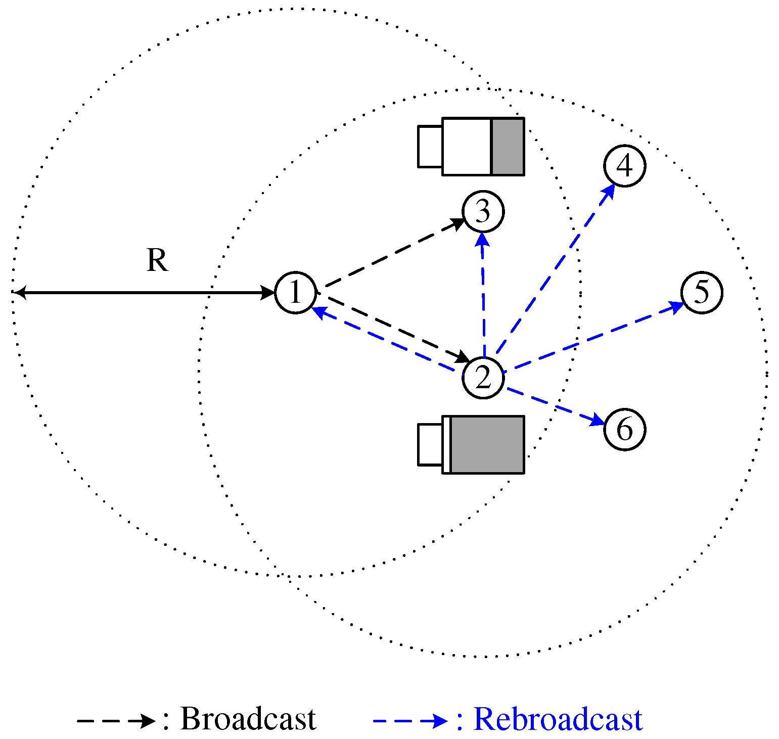
Sun et al. [9] proposed a DCB scheme in which a node receiving a broadcast-message determined an based on the distance between itself and the broadcasting node. Let be the maximum random access delay, R be the maximum transmission range of the node, and D be the distance between the broadcasting and receiving nodes. Then, in order for a node that is far from (close to) the broadcasting node to use a short (long) , the is defined as follows:
where is a uniformly distributed random variable between 0 and 1. In DCB, is defined as a fixed value. Because the coverage area of a node close to the broadcasting node is narrower than that of a node far from the broadcasting node, as shown in Figure 1, DCB mitigates the broadcast-storm problem by prohibiting the broadcast from node 2, thus providing high reachability. In DCB, distance between the broadcasting and receiving nodes can be obtained from a global positioning system (GPS) device. However, when GPS information is unavailable or unreliable, a dissimilarity-based method can be applied, in which the number of neighbors shared by two nodes is used as a performance metric to estimate the relative distance between them [10].
2.2. Neighborhood-Aware Counter-Based Broadcast (NCB) Scheme
Humoud et al. [11] proposed an NCB scheme in which the was determined based on the number of neighbor nodes. Let be a random factor. is set as one of two values: or , where is less than . When a node receives a broadcast-message, it checks the number of its neighbor nodes, n, against the average number of neighbor nodes, . If (), the network is considered sparse (dense), and is set to (). Thus, a node with a large (small) number of neighbor nodes determines a short (long) as follows:
In addition, a node with a large (small) number of neighbor nodes determines a small (large) . In Figure 2, the number of neighbor nodes of node 3 is greater than that of nodes 2 and 4. In this case, NCB mitigates the broadcast-storm problem by prohibiting the broadcasts from nodes 2 and 4, and can guarantee high reachability by rebroadcasting the broadcast-messages of node 3 to more neighbor nodes.
2.3. Battery-Aware Counter-Based Broadcast (BCB) Scheme
Utsu et al. [12] proposed a battery-aware counter-based broadcast (BCB) scheme in which a node receiving a broadcast-message determined both and , based on the remaining battery level. Let , , and be the maximum count threshold value, the remaining battery of a receiving node, and the maximum battery charge, respectively. Then, in order to make a node with a high (low) battery level employ a large (small) , is defined as follows:
where is the ceiling function, which provides the smallest integer greater than or equal to x. On the other hand, is defined by
which is designed for a node with a high (low) battery level to opportunistically employ a short (long) . In Figure 3, the remaining battery level of node 2 is higher than that of node 3. In this case, BCB mitigates the broadcast-storm problem while improving the energy efficiency, by prohibiting the broadcast of node 3 with a low battery level.
As mentioned previously, the DCB and NCB were proposed to achieve high reachability; on the other hand, the BCB was proposed to reduce the node’s energy consumption. Here, we notice that there is a trade-off between the reachability and the energy consumption of nodes in a wireless ad hoc network. If a specific node in DCB is far from the broadcasting node, it transmits broadcast-messages repeatedly, which causes high energy consumption for the node, and network-partition problems may occur. Similar arguments can be applied to a node that has a large number of neighboring nodes in NCB. In contrast, when focusing on reducing the battery consumption of a node, if a specific node in BCB has a high battery level, but is close to the broadcasting node or has a small number of neighboring nodes, it transmits the broadcast-message repeatedly although it is difficult to guarantee high reachability.
3. Proposed Method
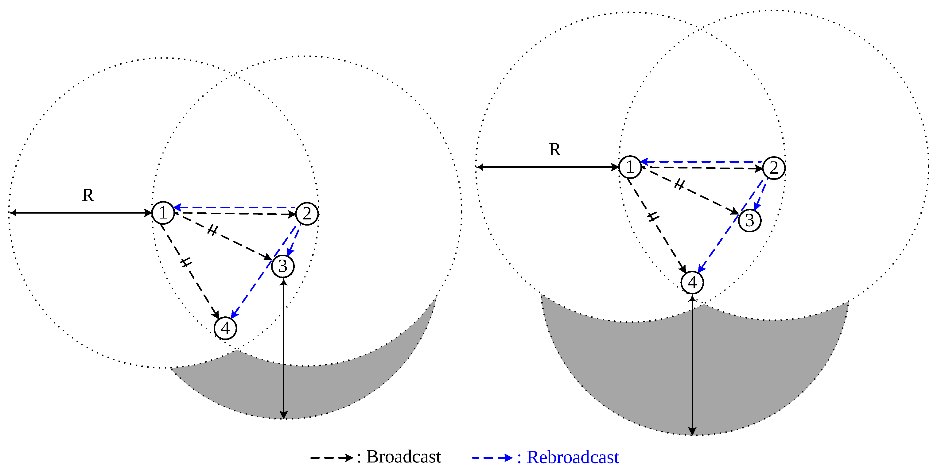
In Figure 4, nodes 3 and 4 are equidistant from node 1 and receive the same broadcast-messages from both nodes 1 and 2. Here, it is noticed that, although nodes 3 and 4 are equally far from node 1, the additional coverage of node 4 is wider than that of node 3 because of the geographical locations of the nodes. This explains the necessity to calculate the exact additional coverage areas of the nodes that receive the same broadcast-message from two different nodes, so that nodes with the largest additional coverage areas are more likely to be selected for rebroadcasting the packets, thereby achieving high reachability.
3.1. Calculation of Additional Coverage Area
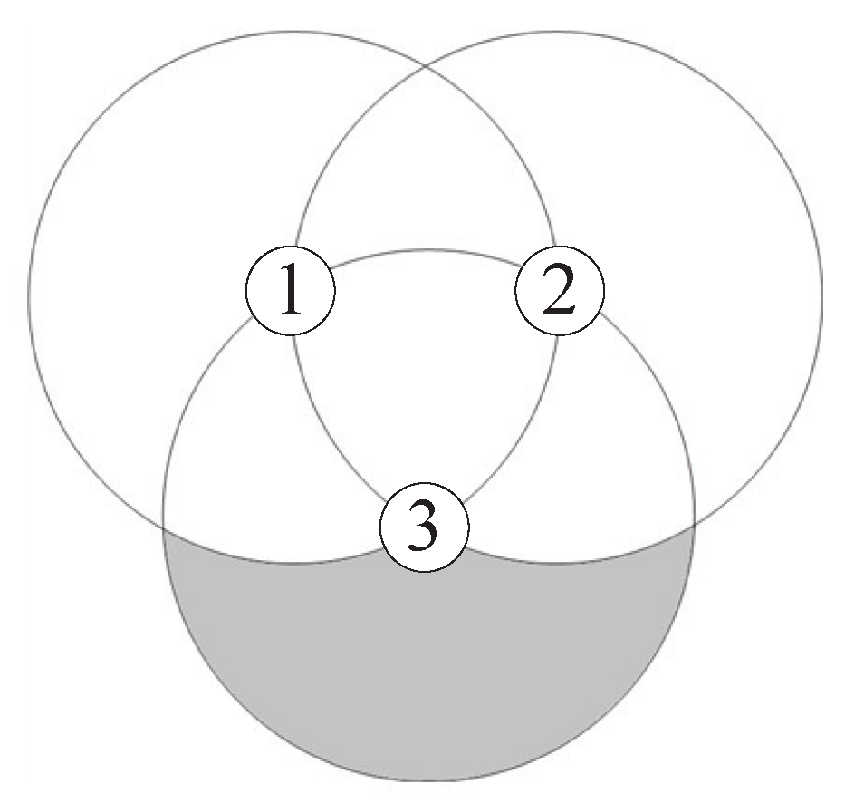
Suppose that node 1 sends a broadcast-message and node 2 rebroadcasts this message. Then, node 3 in the intersection area of the coverage areas of nodes 1 and 2 (shadowed area in Figure 5) receives the same broadcast-message from both nodes 1 and 2. It is assumed that each node is equipped with a GPS, and, thus, the distance between two nodes is recognized by the receiving node via the broadcast-message containing the GPS information of the sender [13]. Let R and be the transmission range of a node and the distance between nodes i and j, respectively. Because node 3 receives the broadcast-messages delivered through node 1 and node 2, it can recognize the distances , and . Let the point of node i in the two-dimensional Euclidean space be and the coordinates of the node i be (, ). Without loss of generality, we assume that node 1 is located at the origin point and that node 2 is on the right-hand side of the x-axis, as shown in Figure 5. That is,
Using , , and , is expressed by
When the distance between two nodes is less than the transmission range R, there are two intersection points between two transmission ranges. Let the two intersection points between the transmission ranges of nodes i and j and the intersection area of the coverage areas of nodes i and j be , , and , respectively. Then, assuming that is located above , as shown in Figure 5, the coordinates of the points and are calculated by
As shown in Figure , the shape of the additional coverage area of node 3 is classified into three cases according to the following conditions for node 3:
- and ,
- and ,
- .
Here, we define the transmission area of node i as and the additional coverage area of node 3 in case i as . Then, from Figure 7, is given by
On the other hand, , , , and is calculated as follows:
Combining Equations (9)–(13) results in the expression of as a function of the distance between the three nodes, which is given by
From Figure 8, the additional coverage area of node 3 is calculated by
Combining Equations (10)–(12) and (15) results in the expression of as a function of the distance between the three nodes, which is given by
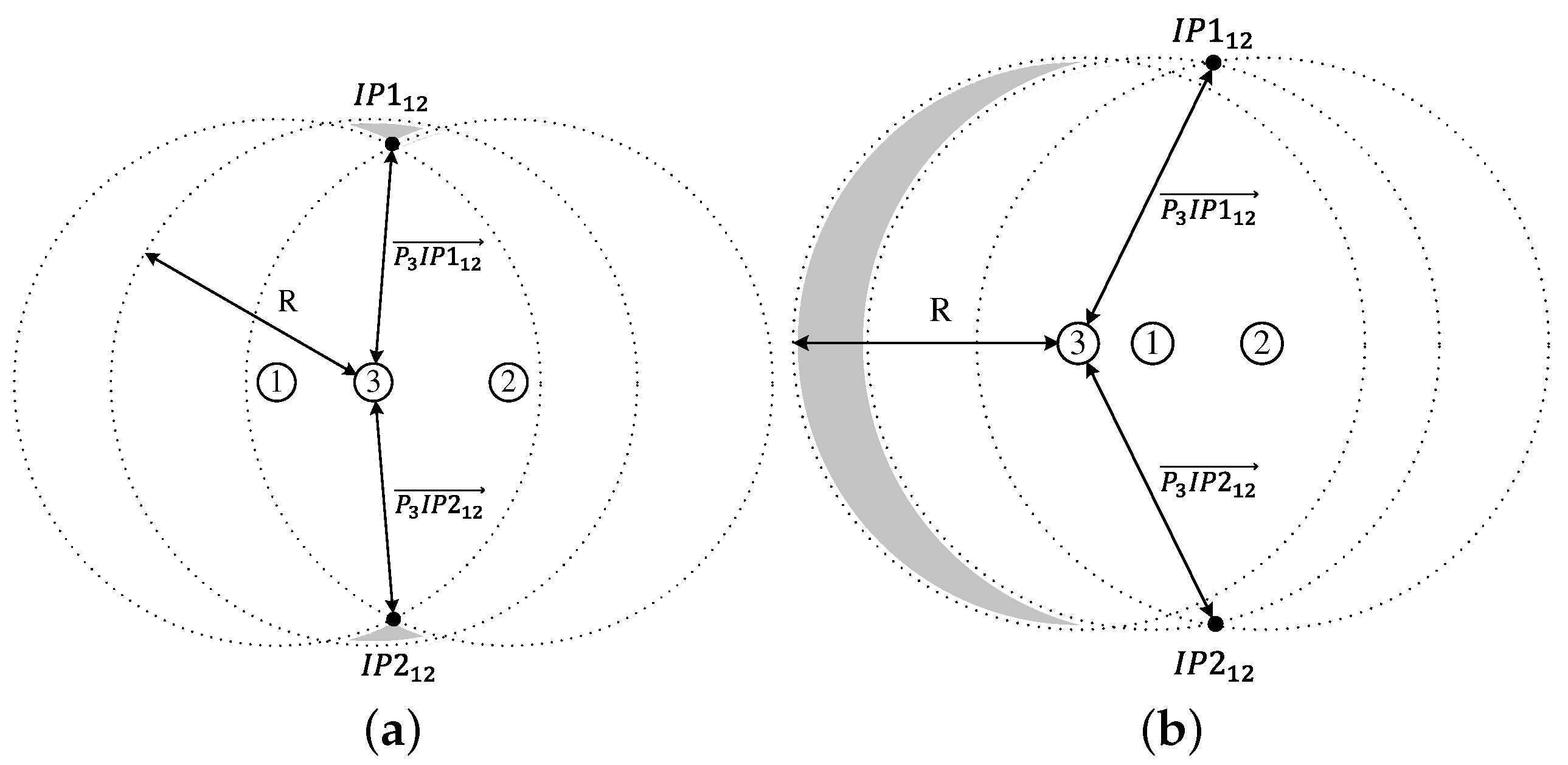
Let the intersection area of the coverages of nodes i, j, and k be . Then, from Figure 9, we can obtain the additional coverage area of node 3 in case 3, which is given by
From Figure 10, is calculated as follows:
where is shown in Figure 10a–d. In case is located below the x-axis, the coordinates of the points and are calculated by
and
respectively. From Heron’s formula, is calculated as follows:
On the other hand, , , and are calculated as follows:
where , , and . Combining Equations (18), (21)–(24) results in the expression of as
In case is located above the x-axis, we can get the from Equation (26) by substituting , , for , , , respectively. The coordinates of the points and are calculated by
and
respectively.
3.2. Proposed Algorithm to Determine a Random Access Delay
As gets longer, the number of nodes transmitting the same broadcast-message increases, and thus, the reachability improves. However, the energy efficiency decreases because the number of transmitted broadcast-messages increases the battery consumptions of the nodes in the network. Thus, it is important to determine the considering the trade-off between the reachability and the energy efficiency of nodes in the network.
Suppose that node 3 is located in the overlapped coverage area of two nodes 1 and 2. , the maximum additional coverage area of node 3, is obtained when the distances between the three nodes are equal to R, that is, , as shown in Figure 11. Thus, is calculated by
In order to allow a node with wider additional coverage area to transmit a broadcast-message earlier than the other nodes, we define the random access delay considering the additional coverage area of a node as
where is the additional coverage area of a node k and is a uniformly distributed random variable between 0 and 1.
For a node that is far from (close to) the broadcasting node to use a short (long) random access delay, we define the random access delay considering the distance between the node and the broadcasting node as
where is the distance between a node k and the broadcasting node.
Let , , and be the remaining battery of node k, maximum battery charge, and random access delay considering the remaining battery level of a node. In order for a node that has high (low) remaining battery to use a short (long) random access delay, we define as
Finally, we define the random access delay of a node k in the network as
where , , and are weighted parameters determined by the density of neighbor nodes, as follows:
where and are the number of neighbor nodes of node k and the total number of nodes in the network, respectively.
When a node is located in a dense area, increases, and a node with a high remaining amount of battery is therefore more likely to be selected for the rebroadcasting, thereby achieving high energy efficiency. On the other hand, when a node is located in a sparse area, and increase, and a node that is far from the broadcasting node or a node that achieves a wider additional coverage area is more likely to be selected for the rebroadcasting. Thus, high reachability and lower redundancy of broadcast-messages can be achieved.
3.3. Proposed Algorithm to Determine a Fixed Count Threshold Value
When large is employed, the number of nodes transmitting the same broadcast-message decreases. Therefore, energy efficiency is improved, but reachability deteriorates. Thus, it is important to determine considering the trade-off between reachability and energy efficiency of nodes in the network.
Let , , and be the minimum and maximum count threshold values, and the average number of neighbor nodes, respectively. Then, the count threshold of node k is defined by
where is defined as
From Equations (37) and (38), the count threshold value of a node in a sparse environment () is determined based on the number of neighbor nodes and has a large value (close to 1) in order to improve reachability and avoid the network-partitioning problem. On the other hand, when a node is in a dense environment (), its count threshold value is set according to the remaining battery of the node with the purpose of reducing the battery consumption of the node and redundancy of the broadcast-messages.
4. Performance Evaluation
4.1. Simulation Environment
The performance of the proposed counter-based broadcast scheme is compared against those of the existing counter-based broadcast schemes: the simplest counter-based broadcast scheme (SCB), in which the node transmits the broadcast-message when , and the DCB, NCB, and BCB introduced in Section 2. Table 1 shows the parameters used in the simulation runs. We assume a static network topology, as can be verified in most of the applications of wireless sensor networks [14,15,16]. In simulation, the source nodes of broadcasting packets are selected using partition degree (PD) and average hop to reach the reachable nodes (AHRN) [17] to guarantee a fair comparison. To observe the performance variations according to node density, we vary the variance of the number of neighbor nodes. It is noticed that the variance of the number of neighbor nodes become small when the nodes are evenly distributed, whereas it is large when the nodes are clustered in a certain area.
For the performance metrics, we employ saved rebroadcast (SRB), reachability (RE), and total energy consumption (TEC). is defined as , where is the number of nodes that actually transmitted the broadcast-message, and is the number of nodes receiving the broadcast-message. is defined as , where is the number of nodes that are reachable, directly or indirectly, from the source node. is defined as the total energy consumption of all nodes in the network, until the simulation run is over. The transmission power, , and reception power, , for a broadcast message are defined as follows [12]:
Monte Carlo simulations for 1000 trials are performed using the C language to evaluate the performance of the proposed and comparison algorithms.
4.2. Simulation Results
Figure 12 shows the as a function of the variance in the number of neighbor nodes and of the count threshold value. For SCB, DCB, and NCB, is used as the count threshold value. In BCB and the proposed counter-based broadcast scheme, an adaptive count threshold is used, as shown in Equations (3) and (37). Generally, increases as the variance of the number of neighbor nodes increases in all the schemes because increases in high-node-density areas. We confirm that the proposed scheme outperforms the other four existing counter-based broadcast schemes in terms of . This is because, under the proposed scheme, a node close to the broadcasting node or a node that cannot achieve a wider additional coverage area is more unlikely to retransmit the broadcast-message in a high-node-density region.
Figure 13 shows as a function of the variance of the number of neighbor nodes. Generally, decreases as the variance increases in all the schemes because disconnection occurs between the nodes located in the low-node-density regions. The simulation results show that BCB has the lowest reachability and SCB has the highest reachability. In addition, it is shown that the proposed scheme has reachability similar to or higher than that of the other existing schemes because, under the proposed scheme, a node that is far from the broadcasting node or a node that can achieve a wider additional coverage area is more likely to retransmit the broadcast-message.
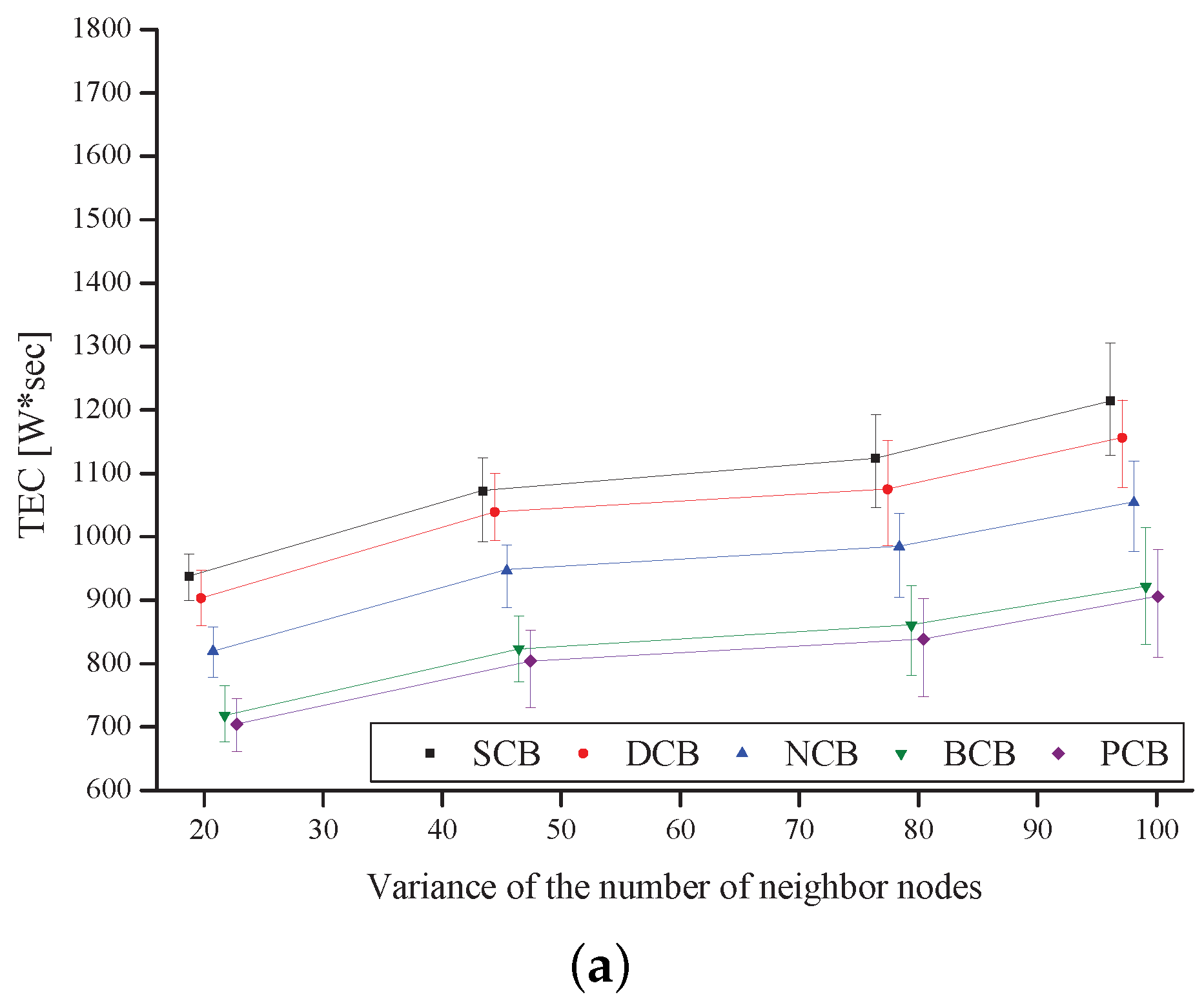
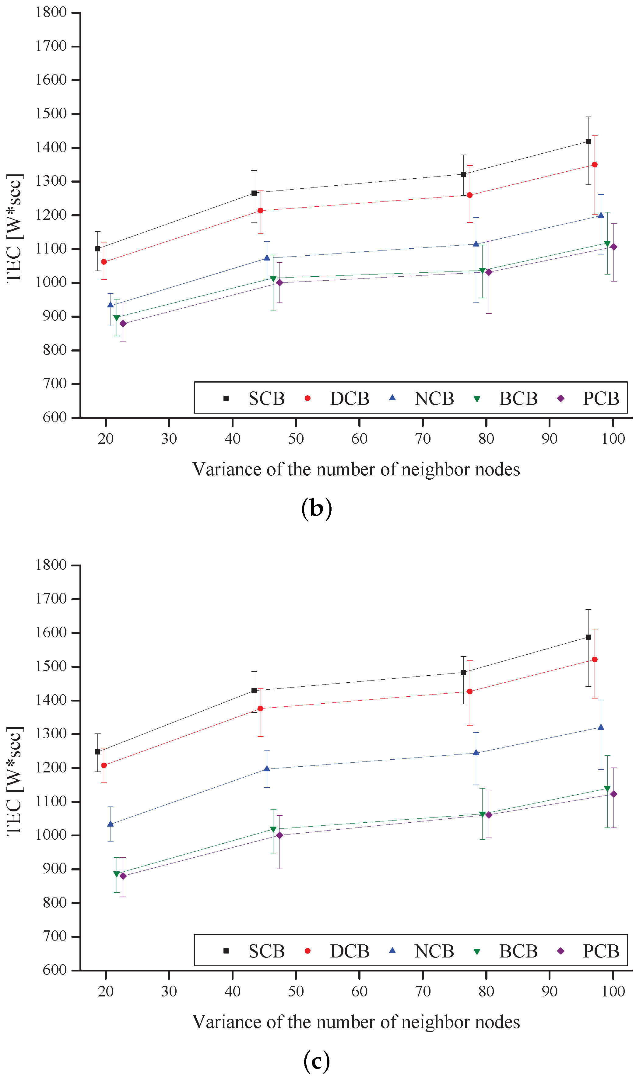
Figure 14 shows as a function of the variance of the number of neighbor nodes. The result shows that increases as increases, for all the schemes. In addition, decreases as the variance increases in all of the schemes because the power consumptions of the nodes located in high-node-density regions decrease. It is noticed that the proposed scheme outperforms the other four existing counter-based broadcast schemes in terms of the TEC because a node that has a high remaining amount of battery retransmits the broadcast-message, under the proposed scheme.
5. Conclusions
In this paper, we proposed a counter-based broadcast scheme for WSNs, which was designed to consider the additional coverage area, distance, node density, and energy efficiency, simultaneously. First, we calculated the exact additional coverage area of a node () to make the proposed scheme reflect the reachability accurately. in the proposed scheme was composed of , , and , which were determined by the remaining battery of a node , the exact additional coverage area of a node , and the distance between a node and the broadcasting node , respectively. In addition, the weight factors for , , and were set according to the density of the node, so that a node in a dense area could achieve high energy efficiency and a node in sparse area could achieve both high reachability and low redundancy in transmitting the broadcast-message. On the other hand, the count threshold value was designed to be determined by either the remaining battery of a node or the network density. Specifically, the of a node in a sparse environment was set according to the number of neighbors to improve reachability, and that of a node in a dense environment was set by the remaining battery of the node to reduce the battery consumption of the node and redundancy of the broadcast-messages. Simulation results showed that the proposed counter-based broadcast scheme outperformed the previous SCB, DCB, NCB, and BCB schemes in terms of saved rebroadcasts, reachability, and total energy consumption. In future work, we have a plan to evaluate the performance of proposed broadcast scheme in a real testbed such as Twistlab, IoT Lab, or Indriya in order to verify the validity of the proposed broadcast scheme and confirm the possible constraints and efficiency issues.
Acknowledgments
This work was supported by the Human Resources Development (No. 20174030201810) of the Korea Institute of Energy Technology Evaluation and Planning (KETEP) grant funded by the Korea government Ministry of Trade, Industry and Energy and the Basic Science Research Program through the National Research Foundation of Korea (NRF) funded by the Ministry of Education, Science and Technology (No. 2015R1D1A1A01060207).
Author Contributions
Ji-Young Jung contributed the paper by correcting some errors in the draft version of the paper, by deriving final results of simulation, by making the revised version of the paper, and by writing the response Letters. Dong-Yoon Seo contributed the paper by deriving initial results of simulation and by making the draft version of the paper. Jung-Ryun Lee was responsible for the main idea, theoretical analysis, coordination and proof reading of the paper.
Conflicts of Interest
The authors declare no conflict of interest.
References
- Zhang, X.; Fan, Y.; Li, C.; Ding, Q. Coverage Efficiency-Based Broadcast Protocol for Asynchronous Wireless Sensor Networks. IEEE Wirel. Commun. Lett. 2016, 5, 76–79. [Google Scholar] [CrossRef]
- Chen, Z.; Liu, A.; Li, Z.; Choi, Y.J.; Sekiya, H.; Li, J. Energy-efficient broadcasting scheme for smart industrial wireless sensor networks. Mob. Inf. Syst. 2017, 2017, 1–17. [Google Scholar] [CrossRef]
- Qiu, T.; Xia, F.; Ding, Y.; Liu, L.; Wan, J. A neighbour-based load-balanced packet dissemination scheme for wireless sensor networks. Int. J. Sens. Netw. 2016, 22, 220–228. [Google Scholar] [CrossRef]
- Krivtsova, I.; Lebedev, I.; Sukhoparov, M.; Bazhayev, N.; Zikratov, I.; Ometov, A.; Hosek, J. Implementing a broadcast storm attack on a mission-critical wireless sensor network. In Proceedings of the International Conference on Wired/Wireless Internet Communication, Thessaloniki, Greece, 25–27 May 2016; pp. 297–308. [Google Scholar] [CrossRef]
- Cheng, P.; Qi, Y.; Xin, K.; Chen, J.; Xie, L. Energy-Efficient Data Forwarding for State Estimation in Multi-Hop Wireless Sensor Networks. IEEE Trans. Autom. Control 2016, 61, 1322–1327. [Google Scholar] [CrossRef]
- Chanak, P.; Banerjee, I.; Sherratt, R.S. Energy-aware distributed routing algorithm to tolerate network failure in wireless sensor networks. Ad Hoc Netw. 2016, 56, 158–172. [Google Scholar] [CrossRef]
- Reina, D.G.; Toral, S.L.; Johnson, P.; Barrero, F. A survey on probabilistic broadcast schemes for wireless ad hoc networks. Ad Hoc Netw. 2015, 25, 263–292. [Google Scholar] [CrossRef]
- Liang, C.; Lim, S.; Min, M.; Wang, W. Pseudo geometric broadcast protocols in wireless sensor networks: Design, evaluation, and analysis. Comput. Commun. 2017, 101, 82–93. [Google Scholar] [CrossRef]
- Chen, C.; Hsu, C.K.; Wang, H.K. A distance-aware counter-based broadcast scheme for wireless ad hoc networks. In Proceedings of the IEEE Military Communications Conference (MILCOM), Atlantic City, NJ, USA, 17–20 October 2005; pp. 1052–1058. [Google Scholar]
- Reina, D.G.; Günes, M.; Toral, S.L. Real experimentation of probabilistic broadcasting algorithms based on dissimilarity metrics for multi-hop ad hoc networks. Ad Hoc Netw. 2016, 47, 1–15. [Google Scholar] [CrossRef]
- Al-Humoud, S.O.; Mackenzie, L.M.; Abdulai, J. Neighbourhood-Aware Counter-Based Broadcast Scheme for Wireless Ad Hoc Networks. In Proceedings of the GLOBECOM Workshops, New Orleans, LA, USA, 30 November–4 December 2008; pp. 1–6. [Google Scholar]
- Utsu, K.; Sano, H.; Kassymov, T.; Nishikawa, H.; Ishii, H. A new dynamic counter-based broadcasting scheme for Mobile Ad hoc Networks. Simul. Modell. Pract. Theory 2011, 19, 553–563. [Google Scholar] [CrossRef]
- Kobayashi, K.; Totani, Y.; Sano, H.; Utsu, K.; Ishii, H. A proposal on location data supplementing information transfer method over MANET. J. Supercomput. 2016, 72, 1226–1236. [Google Scholar] [CrossRef]
- Gupta, V.; Doja, M.N. Skewness Removal of LEACH Protocol for Wireless Sensor Networks. In Proceedings of the Recent Advances in Mathematics, Statistics and Computer Science, Bihar, India, 29–31 May 2015; pp. 561–568. [Google Scholar] [CrossRef]
- Kumar, R.; Kumar, D. Multi-objective fractional artificial bee colony algorithm to energy aware routing protocol in wireless sensor network. Wirel. Netw. 2016, 22, 1461–1474. [Google Scholar] [CrossRef]
- Huang, J.; Ruan, D.; Hong, Y.; Zhao, Z.; Zheng, H. IMHRP: Improved Multi-Hop Routing Protocol for Wireless Sensor Networks. J. Phys. 2017, 910, 1–11. [Google Scholar] [CrossRef]
- García-Campos, J.M.; Reina, D.G.; Sánchez-García, J.; Toral, S.L. A Simulation methodology for Conducting Unbiased and Reliable Evaluation of MANET Communication Protocols in Disaster Scenarios. In Smart Technologies for Emergency Response and Disaster Management; IGI Global: Hershey, PA, USA, 2017; Volume 4, pp. 106–143. [Google Scholar] [CrossRef]
Figure 1.
Distance-aware counter-based broadcast scheme.

Figure 2.
Neighborhood-aware counter-based broadcast scheme.

Figure 3.
Battery-aware counter-based broadcast scheme.

Figure 4.
Different additional coverage areas of node 3 and node 4.

Figure 5.
Nodes in the shadowed area receive the same broadcast-message from nodes 1 and 2.

Figure 6.


Figure 7.
The additional coverage area of node 3 in case 1. (a) ; (b) ; (c) ; (d) ; (e) .

Figure 8.
The additional coverage area of node 3 in case 2. (a) ; (b) ; (c) .

Figure 9.
The additional coverage area of node 3 in case 3. (a) ; (b) ; (c) ; (d) ; (e) .

Figure 10.
An intersection area within the transmission range of three nodes. (a) ; (b) ; (c) ; (d) ; (e) .
Figure 10.
An intersection area within the transmission range of three nodes. (a) ; (b) ; (c) ; (d) ; (e) .

Figure 11.
The maximum additional coverage area achieved by node 3

Figure 12.


Figure 13.


Figure 14.


Table 1.
Simulation parameters.
| Parameter | Value |
|---|---|
| Topology | Ad-hoc network |
| Network size | 500 × 500 m2 |
| Number of nodes | 120 |
| Transmission range (R) | 100 m |
| Packet type | Constant-bit-rate (CBR) packet |
| Packet generation period | 1 s |
| Broadcast message length | 200 bytes |
| Simulation run time | 10 min |
| Energy distribution | Uniformly random in |
| Iteration | 1000 |
| 1 | |
| 3 ∼ 5 | |
| Variance of the number of neighbor nodes | 20.73, 45.42, 78.41, 98.12 |
© 2018 by the authors. Licensee MDPI, Basel, Switzerland. This article is an open access article distributed under the terms and conditions of the Creative Commons Attribution (CC BY) license (http://creativecommons.org/licenses/by/4.0/).
Share and Cite
MDPI and ACS Style
Jung, J.-Y.; Seo, D.-Y.; Lee, J.-R. Counter-Based Broadcast Scheme Considering Reachability, Network Density, and Energy Efficiency for Wireless Sensor Networks. Sensors 2018, 18, 120. https://doi.org/10.3390/s18010120
AMA Style
Jung J-Y, Seo D-Y, Lee J-R. Counter-Based Broadcast Scheme Considering Reachability, Network Density, and Energy Efficiency for Wireless Sensor Networks. Sensors. 2018; 18(1):120. https://doi.org/10.3390/s18010120
Chicago/Turabian StyleJung, Ji-Young, Dong-Yoon Seo, and Jung-Ryun Lee. 2018. "Counter-Based Broadcast Scheme Considering Reachability, Network Density, and Energy Efficiency for Wireless Sensor Networks" Sensors 18, no. 1: 120. https://doi.org/10.3390/s18010120
Note that from the first issue of 2016, this journal uses article numbers instead of page numbers. See further details here.