OFDM with Index Modulation for Asynchronous mMTC Networks


1
Department of Electrical and Electronics Engineering, Istanbul Medipol University, 34810 Istanbul, Turkey
2
Department of Electrical Engineering, University of South Florida, Tampa, FL 33620, USA
*
Author to whom correspondence should be addressed.
Sensors 2018, 18(4), 1280; https://doi.org/10.3390/s18041280
Submission received: 1 March 2018
/
Revised: 13 April 2018
/
Accepted: 19 April 2018
/
Published: 21 April 2018
(This article belongs to the Special Issue Emerging Methodologies and Practical Solutions for M2M and D2D Communications in the Internet of Things Era)
Abstract
:One of the critical missions for next-generation wireless communication systems is to fulfill the high demand for massive Machine-Type Communications (mMTC). In mMTC systems, a sporadic transmission is performed between machine users and base station (BS). Lack of coordination between the users and BS in time destroys orthogonality between the subcarriers, and causes inter-carrier interference (ICI). Therefore, providing services to asynchronous massive machine users is a major challenge for Orthogonal Frequency Division Multiplexing (OFDM). In this study, OFDM with index modulation (OFDM-IM) is proposed as an eligible solution to alleviate ICI caused by asynchronous transmission in uncoordinated mMTC networks. In OFDM-IM, data transmission is performed not only by modulated subcarriers but also by the indices of active subcarriers. Unlike classical OFDM, fractional subcarrier activation leads to less ICI in OFDM-IM technology. A novel subcarrier mapping scheme (SMS) named as Inner Subcarrier Activation is proposed to further alleviate adjacent user interference in asynchronous OFDM-IM-based systems. ISA reduces inter-user interference since it gives more activation priority to inner subcarriers compared with the existing SMS-s. The superiority of the proposed SMS is shown through both theoretical analysis and computer-based simulations in comparison to existing mapping schemes for asynchronous systems.
1. Introduction
Wireless communication systems can be classified into two fundamental categories, namely human-user-based and machine-user-based from the perspective of 5G use cases and applications [1,2]. Current technology gives priority to human-based communications. However, the emerging idea of Massive Machine-Type Communications (mMTC) such as Internet of Things (IoT), vehicle-to-vehicle (V2V), vehicle-to-infrastructure (V2I), control of autonomous vehicles and smart cities with millions of sensors poses various demands for the next-generation networks [3,4,5]. mMTC, where a large number of machine users sporadically communicate with a given base station (BS), leads to asynchronous uplink transmission associated with multi-user interference (MUI). Hence, handling of asynchronous impairments is expected to be one of the most challenging problems for mMTC networks [2,3,6].
Orthogonal frequency division multiplexing (OFDM) has been well studied by academia in the last two decades [7]. It has been shown that OFDM is robust against inter-symbol interference (ISI) with the aid of cyclic prefix (CP), which turns the linear convolution with the channel into a circular convolution [8]. However, OFDM is severely effected from inter-carrier interference (ICI) due to loss of subcarrier orthogonality.
In multi-user OFDM, the users must be aligned in the time and frequency domains in order to maintain the orthogonality between the subcarriers. However, multi-user time alignment is infeasible in asynchronous mMTC-based systems, since signals transmitted from the users at different distances from the BS arrive with different time delays. Time misalignment causes ICI between the users. Furthermore, it is expected that the impact of MUI becomes significant when different power levels are assigned to the machine users, with respect to the applications or used cases [9]. Even if equal power is distributed to the users, as far as signals travel through different paths, power misalignment occurs at the BS.
In literature, 5G candidate waveforms including filter bank multi-carrier (FBMC), generalized frequency-division multiplexing (GFDM) and universal filtered multi-carrier (UFMC) are studied to relax MUI by suppressing out-of-band emission (OOBE) [2,10,11,12]. Moreover, inserting guard-bands between the users is used to further suppress OOBE [9,13]. However, filtering process increases the system complexity and use of guard-bands reduce spectral efficiency. In [14], a new perspective is presented to reduce MUI by clustering of the channel impulse response.
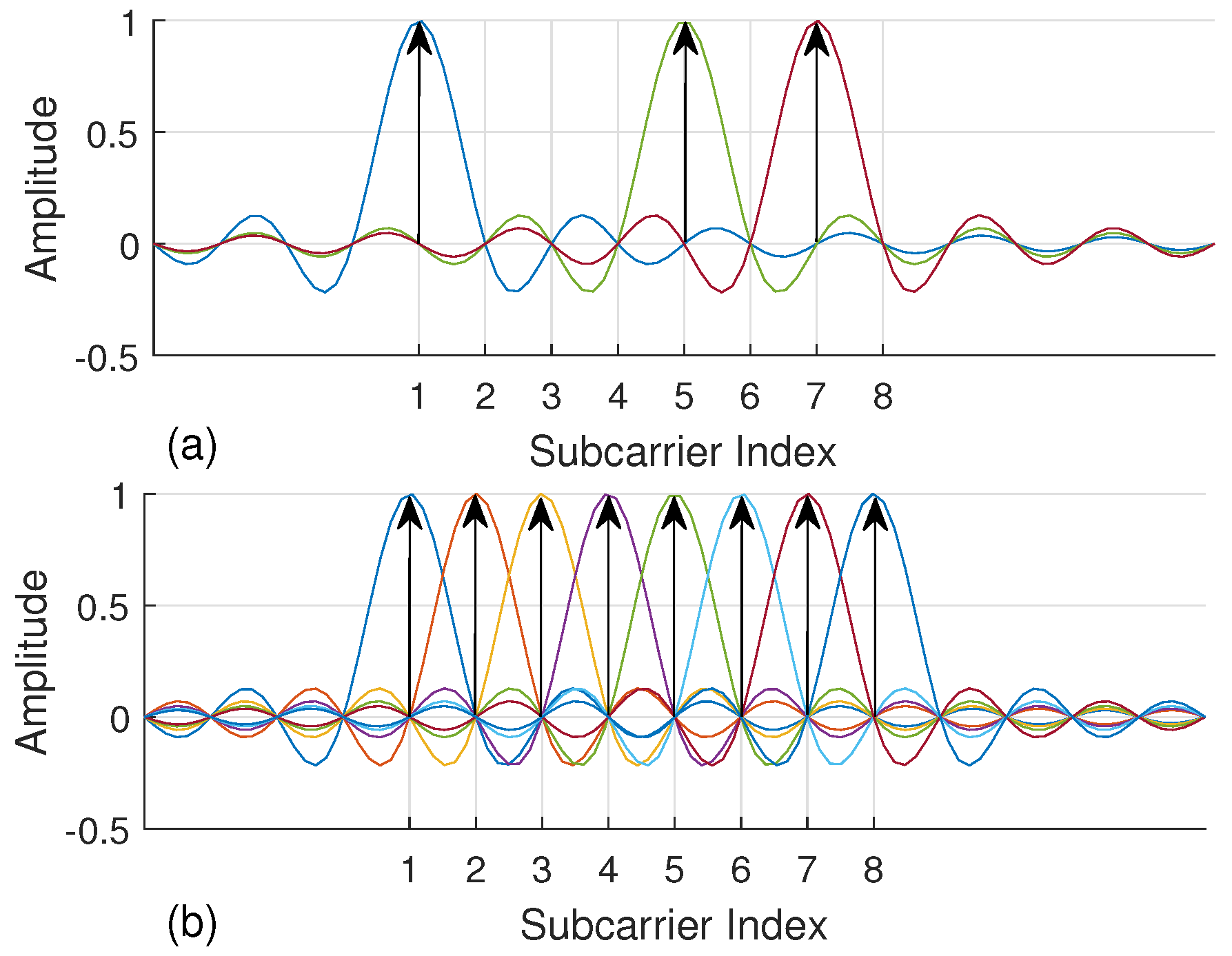
Recently, the proliferation of index modulation (IM) has introduced new research perspectives for 5G wireless systems [15]. At first, IM has been presented as spatial modulation technique (SM) for multiple-input multiple-output (MIMO) systems to convey information by antenna indices [16]. The notion of IM is also extended to OFDM and named as OFDM with index modulation (OFDM-IM), which carries information not only by data symbols but also by the indices of active subcarriers [17,18]. In contrast to conventional OFDM, not all subcarriers are utilized in OFDM-IM. In Figure 1, a simple example is illustrated for an OFDM-IM subblock consisting of eight subcarriers, where three of them are activated to convey data symbols. Extra bits are carried by the indices of active subcarriers to compensate inefficient use of spectrum. In addition, fractional subcarrier activation brings in diversity order as well as less energy consumption [15]. Hence, OFDM-IM provides a flexible and adaptive structure which can be optimized by considering the demands of next-generation communication systems.
Mapping incoming bits to the subcarrier indices is one of the flexible properties of OFDM-IM. In the literature, three subcarrier mapping schemes (SMS) have been proposed to improve error performance and to reduce complexity of the OFDM-IM-based systems. Look-up table (LUT) is the first technique used as a mapping scheme, which uses same storage table at both transmitter and receiver [18]. However, it is not practical for large OFDM-IM subblock sizes. Therefore, Combinatorial method (COM), which does not require storage table, is proposed in [18]. Due to non-uniform subcarrier activation, COM leads to an unequal protection of the transmitted information bits that makes ultimate error performance worse. Hence, equiprobable subcarrier activation (ESA) technique is proposed in [19]. It is observed an enhancement up to 1.9 dB on error rate performance by using ESA for noisy multipath fading channels.
Performance of OFDM-IM is investigated under various impairments by researchers. In [18], it is shown that OFDM-IM under frequency selective fading channels impairment with high mobility is more robust than OFDM. Due to robustness against mobility, it is offered as a candidate for vehicle to X (V2X) communication systems [20]. ICI stemming from carrier frequency offset (CFO) impairment is evaluated by introducing notions of inter-subblock and intra-subblock interference for OFDM-IM [21]. It is observed that OFDM-IM is superior to current technology when the signal is impaired by CFO. In [22], both ICI and ISI is analyzed and mitigated using optimal tone spacing between adjacent subcarriers.
To the best of our knowledge, the performance of OFDM-IM under asynchronous transmission has not been characterized or investigated. In this paper, OFDM-IM is proposed as a candidate solution for uncoordinated mMTC networks. A novel subcarrier mapping scheme (ISA) is proposed to provide further enhancement of OFDM-IM performance for asynchronous systems. It is compared with the current ESA and COM mapping methods. The comparison is performed for various OFDM-IM subblock parameters to evaluate impact of flexibility properties of OFDM-IM. Not only time misalignment but also power difference between the machine users is considered in this study. In addition, ICI analysis is performed and the performance of the OFDM-IM is compared with conventional OFDM in the present of time and power offset between the users.
The remainder of this work is organized as follows. Section 2 introduces the multi-user OFDM-IM system model for asynchronous transmission. In Section 3, ICI analysis is provided for OFDM-IM. In Section 4, existing SMS are revisited and a novel mapping technique is proposed. Numerical results are given in Section 5. Finally, some concluding remarks are provided for OFDM-IM technology with mMTC in Section 6.
2. System Model
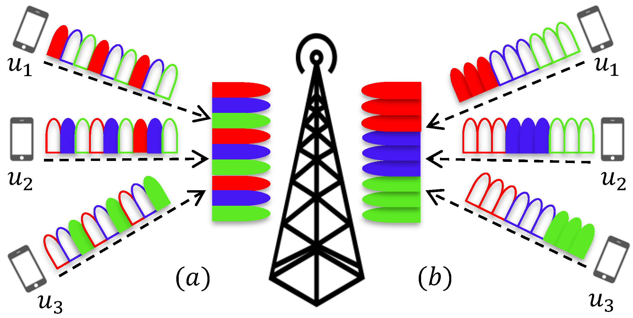
This section introduces an uplink system model where U users independently communicate with the base station (BS) through a frequency selective channel. A simple uplink system example is presented in Figure 2. Each user’s information is modulated with OFDM-IM. A total of N subcarriers is equally split between the users, and subcarriers are dedicated to u-th user, with . Assignment of OFDM-IM subblocks to the users can be performed in two ways, either interleaved-based or localized-based. Interleaved-based assignment mixes the users’ subblocks, while localized-based assignment successively places each user’s subblocks, as visualized in Figure 2.
In Figure 3, time domain signal that belongs to u-th user is expressed as . It is assumed that , which reaches first to the BS, is considered to be reference signal for the BS. Each user’s signal arrives to the BS with a different time offset (TO) with respect to since they can be placed at different distances from the BS or can be transmitted at different times. The transmitted signal from each user passes through its own channel . All the channels are uncorrelated with each other. Later, individual signals transmitted from all the users is superimposed, and additive white Gaussian noise (AWGN) is added to the superimposed signal . Due to the time misalignments, orthogonality between the machine users cannot be maintained anymore. Therefore, ICI between the users occurs and degrades the system performance. Table 1 presents symbols used in the study and their descriptions. Further insights about asynchronous mMTC transmission with OFDM-IM are given in following subsection.
OFDM-IM Transmission Model
In this work, it is considered N size OFDM-IM block, where subcarriers are equally split into G subblocks. Each subblock consists of subcarriers and v out of s are selected to transmit M-ary data symbols with . As mentioned in Section 1, in contrast with conventional OFDM , not all subcarriers are utilized for M-ary symbols. Hence, the loss of spectral efficiency is compensated by the used subcarrier indices that convey additional information bits.
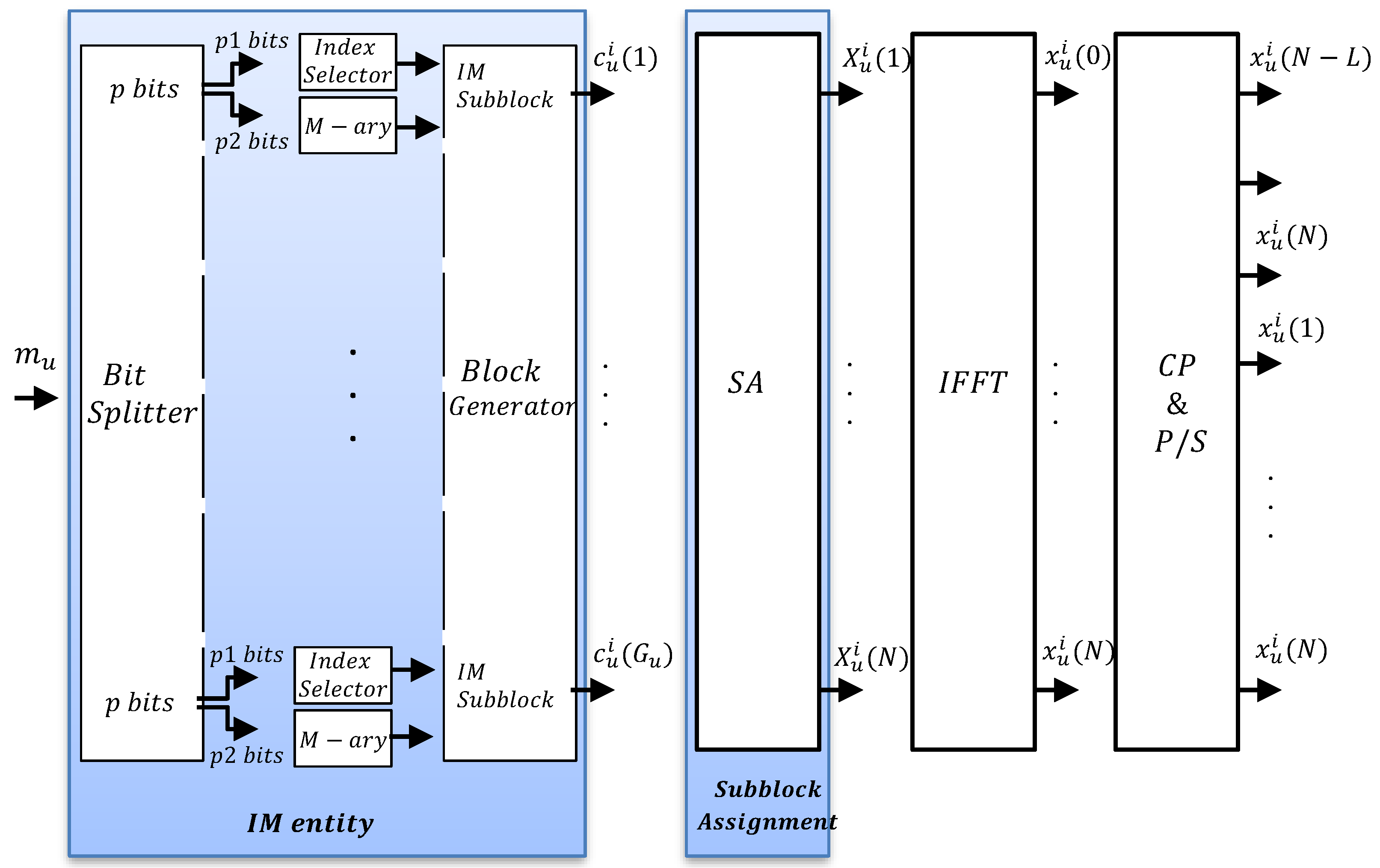
In multi-user transmission, each user has a total of available subblocks to carry bit stream, with . When all the subcarriers are assigned to one user, equals to G. Block diagram for asynchronous OFDM-IM transmitter is shown in Figure 4. Each OFDM-IM subblock consists of bit stream, which is divided into and bits. The indices of active subcarriers are defined from bit stream, while remaining bit stream is mapped to conventional M-ary symbols , which are carried by the activated subcarriers. Division of the p bit stream is illustrated by “IM” entity in Figure 4. The indices of active subcarriers of u-th user for l-th subblock are defined as
where for . Thus, total number of conveyed bits per OFDM-IM subblock is calculated as
where and denote floor function and binomial coefficient, respectively. The number of transmitted bits per user is
l-th subblock belongs to i-th data block of u-th user is represented as
where . represents the data symbols. Later, as illustrated by “Block Generator” in Figure 4, subblocks are combined to form i-th data block of u-th user expressed as follow
out of subcarriers carry M-ary symbols and the rest equal to zero. “IM” entity in Figure 4 full demonstrates the process of generating the frequency domain data samples for u-th user.
Once is generated, it passes through the multi-user “Subblock assignment” (SA) entity, as in Figure 4. SA performs either localized assignment or interleaved assignment for , and inserts N- zeros to the subcarriers assigned to the other users. Then, i-th OFDM-IM block of u-th user is generated as follow
Time domain samples for i-th block of u-th user are obtained by inverse-Fast Fourier Transform (IFFT) process shown in Figure 4 as
A cyclic prefix (CP) with length L is appended to the beginning of to prevent inter-symbol interference (ISI) due to time dispersion of the channel [8]. Time domain signal of u-th user passes through multipath channel. The signal experiences Rayleigh fading. Channel impulse response coefficients between u-th user and the BS for i-th block are characterized as
where denotes total number of taps, r is the path index and is the delay of the r-th path. It is assumed that maximum excess delay of the channel is smaller than CP size, and path gains are Gaussian random variables with distribution . The signal is received as
where ∗ denotes convolution process. At the BS, signal transmitted from all the machine users are superimposed as follow
is AWGN with distribution of .
At the receiver, time offset is removed from the superimposed signal to obtain the signal belonging to u-th user. Fast Fourier Transform (FFT) is applied to obtain the frequency domain samples . Then, deassignment process, which refers to the inverse process of the SA, is applied to get only u-th user data blocks . The indices of active subcarriers are detected by using maximum likelihood (ML) or log-likelihood ratio (LLR) detectors. ML detector checks all the possible subcarriers combinations and information symbols to find the most optimum joint decision. LLR receiver first detects active subcarriers and then information symbols carried by the detected subcarriers are demodulated [18].
3. ICI Analysis in OFDM-IM Systems
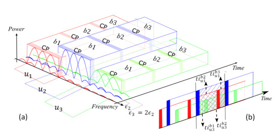
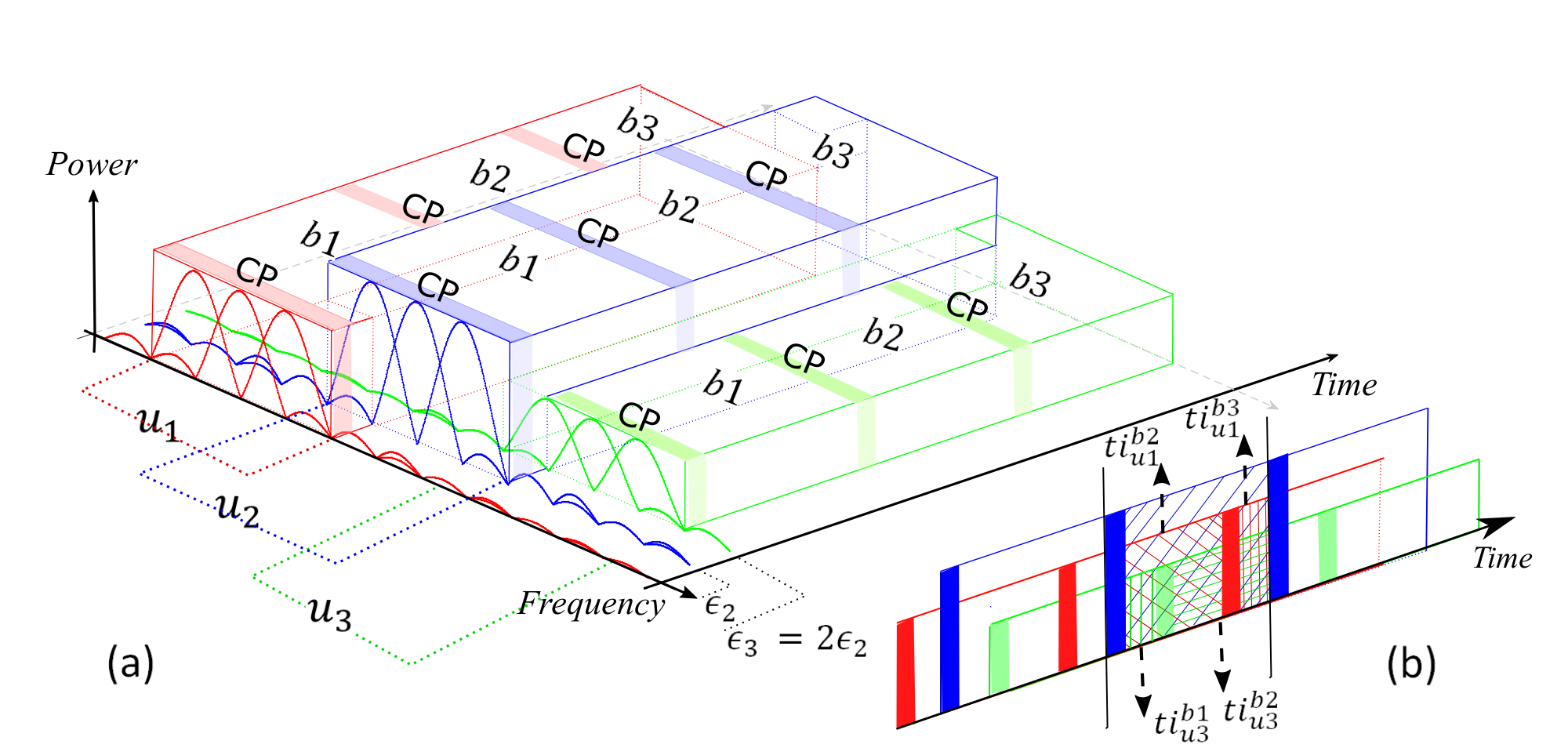
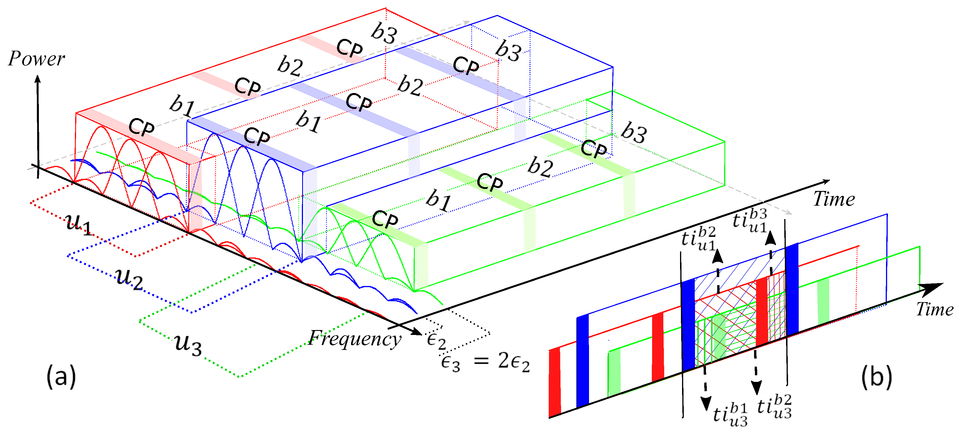
Consider a system model which includes users with 3 OFDM-IM blocks to analyze ICI because of time offset between the users. These users transmit sporadically in adjacent bands with different transmit power levels, as illustrated in Figure 5a. For the sake of simplicity, it is assumed that equal time offset between the adjacent users. Notations of , and in the figure denote first, second and third OFDM-IM block, respectively.
In [6], ICI model is calculated for OFDM systems under time misalignment. Besides time offset, the model is modified for uncoordinated OFDM-IM systems by considering the fact that power difference between the machine users. In contrast to OFDM, only the active subcarriers of the users’ cause ICI in OFDM-IM. Therefore, the indices of interferer subcarriers belong to .
In our calculations, shows the interference coming from -th user to the -th user while denotes the interference caused by l-th block of -th user. denotes the active subcarrier indices of u-th user for all the subblocks. Figure 5b shows the superimposed signal at the BS. As illustrated in the figure, time domain interference for the 2-nd symbol of 2-nd user is calculated as
where and , and they are expressed as
where and refers to power difference between the 1-st and 2-nd user, and the 3-rd and 2-nd user, respectively.
In the frequency domain, ICI is calculated by taking FFT for , and it is expressed as
ICI for first user and third user is obtained as
In this paper, it is considered that subcarriers belong to u-th user are orthogonal to each other while machine users’ subcarriers are interfering with each other due to the time offset between them. For this reason, interference coming from other users to u-th user is mainly determined by its adjacent users’ edge subcarriers. Since the subcarriers are sinc functions in frequency domain, inner subcarriers’ sidelobes have less impact on the ICI compared to the edge subcarriers, as explained in [13,23,24]. Therefore, more users can be considered, but the interference coming from users that are not adjacent with the u-th user becomes much smaller.
4. OFDM-IM Subcarrier Mapping Schemes
In this section, the existing SMS-s in the literature for OFDM-IM are revised, and the proposed mapping scheme ISA is explained in details.
4.1. Existing SMS-s
4.1.1. LUT
The method requires at both transmitter and receiver side a look-up table with the size to store all possible combinations of the active subcarrier indicies with respect to -bit stream. An example of LUT with , and is illustrated in Table 2. denotes bit streams corresponding to each index combination , with . The size of look-up table significantly increases the system complexity with the increase of the . Therefore, LUT scheme become infeasible for large .
At the receiver, ML detector is used to make a joint decision for active subcarrier indices with M-ary data symbols [18].
4.1.2. COM
In contrast to LUT method, storage tables at the transmitter and receiver are not required. It assigns a specific lexicographically ordered sequence with for each possible index combination . The -bit stream is converted to a natural number E, which is converted to a specific sequence as follow
To select components, we start from the condition that satisfies and then choose the maximal that satisfies until and then the index combination is obtained as . Detailed information about COM can be found in [18].
In the receiver, firstly is identified for a given subblock by using LLR detector, and is mapped to its corresponding decimal number E, which passes through bit to decimal converter to get bit stream.
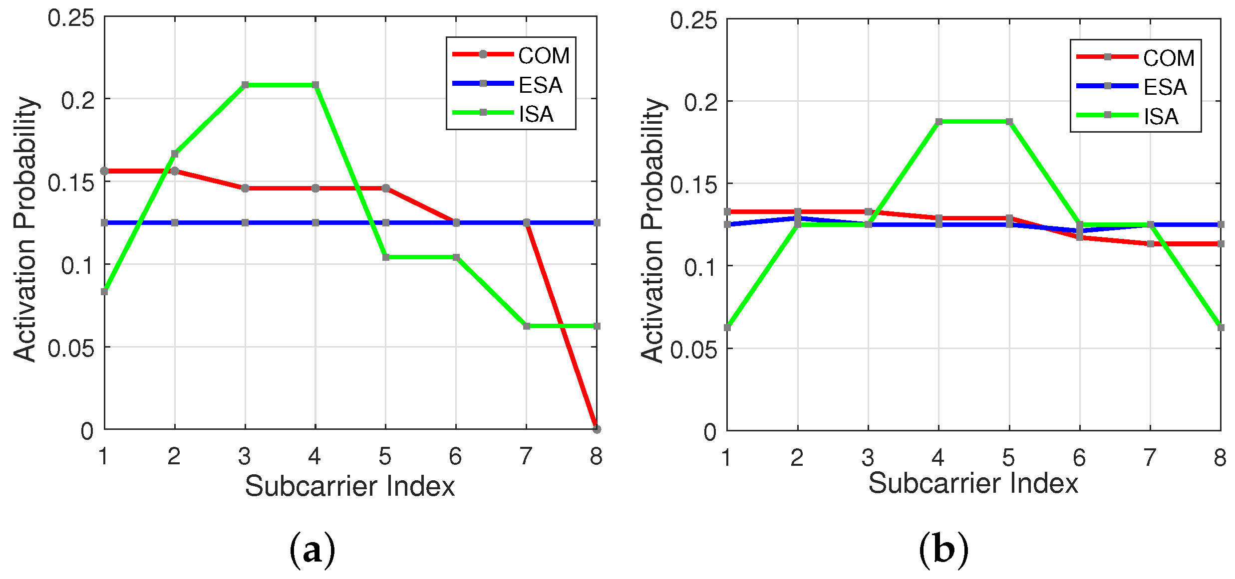
In Figure 6a,b subcarrier activation probability is represented by the red line for COM scheme. As seen in the figures, initial subcarriers have higher usage probability in comparison to the last ones, especially for and .
4.1.3. ESA
In contrast with COM method, ESA offers as much as possible equiprobable subcarrier activation opportunity as illustrated in Figure 6a,b by the blue line [19]. A small table named as adjacent subcarrier distance vector (ASDV) is present at both transmitter and receiver to find basic combinations , which belongs to . By using column cyclic shift new active subcarrier combinations are generated from the . The new combinations have the same ASDV with the corresponding basic pattern . Note that some index combinations generated from cyclic shift of -s can be the same. In this case, ASDV considers only one from repeated patterns and disregards the rest. This idea successively is applied all over until we get all possible subcarrier combinations . Selection of the basic patterns are explained in [19]. At the receiver side, LLR receiver is used to find that is mapped to -bit stream for a given subblock.
4.2. Proposed SMS: ISA
Aforementioned SMS-s are designed for synchronous communication systems, which leads to equal noise power level at each subcarrier. Therefore, in this study new mapping scheme ISA, which stands for inner subcarrier activation, is proposed and explained to alleviate the ICI due to sporadic transmission in mMTC.
ISA scheme gives a higher activation probability to the subcarriers located at the center part of the OFDM-IM subblock, as illustrated in Figure 6a,b by the green line. OOBE coming from inner subcarrier is less than that of edge subcarriers [23]. Therefore, each user experiences less interference from its adjacent users.
ISA scheme is based on the COM scheme, which directly maps bits to subcarrier indices , and vise versa. As calculated in line 1 of Algorithm 1, a subblock with s subcarriers is divided into two parts, where first part and second part contains subcarriers and subcarriers, respectively. subcarriers and subcarriers are activated to carry data information symbols. Indices for active subcarriers are selected by flipped version of COM method, which is calculated from line 4 through 6. Conventional COM method is used to select subcarrier indices as shown in line 7. Consequently, indices of active subcarriers for are composed of and , as shown in line 8. In ISA, equals . This results in less spectral efficiency for some combinations of s and v.
| Algorithm 1 ISA mapper. |
|
At the receiver, LLR detectors are used to know the active subcarrier indices , as shown in line 3 through 6 of Algorithm 2.
| Algorithm 2 ISA demapper. |
|
The receiver first calculates the LLR values with respect to each subcarrier as
where and denotes the probability of k-th subcarrier being active and inactive, respectively. shows total distortion of the system due to both ICI and noise, and is channel frequency response (CFR) for u-th user. After calculation of values for a subblock, v out of them with highest define the active subcarriers. The subcarrier index patterns are converted to lexicographically ordered sequences and . By using Equation (21), these sequences are mapped to decimal numbers and . Then, and undergo decimal-to-bit converter to obtain and bit streams as illustrated in line 7 and 8, respectively. bit stream is a concatenation of and , as shown in line 9.
Due to the fact that proposed ISA mapper is based on COM mapper, ISA does not bring additional complexity to the system. Unlike LUT and ESA schemes, storage tables are not required for ISA. Moreover, ISA technique gives higher activation probability to the inner subcarriers with low and vice versa. Therefore, the reliability of calculated LLR values is maximum for asynchronous transmission with the aid of ISA regarding to Equation (22). In other words, detection performance of the active subcarriers under asynchronous transmission is increased by ISA.
5. Numerical Results and Discussion
This section is dedicated to evaluating the performance of OFDM-IM and OFDM-based systems for asynchronous mMTC networks. Theoretical results for ICI due to both time offset and power difference between the users are first validated by computer-based simulations. Secondly, BER performance for OFDM-IM with three different subcarrier mapping schemes including COM, ESA and ISA are shown to compare their performance for uncoordinated networks. In this study, we assume three users are sporadically transmitting to the BS. Available N = 120 subcarriers are equally split between the users. The system is tested over = 10 tap frequency-selective Rayleigh fading channel. A CP size is adjusted as to prevent ISI for each user. BPSK modulation is used for the machine users. MATLAB software is used for the simulations.
In all simulations, two different subblock parameters are preferred to make a proper comparison between the subcarrier mapping methods. OFDM-IM with ESA for subblock parameters s = 8 and v = 3 offers the best performance in comparison to COM, since it benefits the most from frequency selectivity of the channel. On the other hand, the performance of ESA becomes similar to COM for the parameters s = 8 and v = 4 due to loss of selectivity, which is caused by usage of almost all subcarrier combinations [19]. In addition, two different time offset between the users are considered. Minimum and maximum time offset are adjusted as 24 and , respectively. Power differences between the users obey uniform distribution in a range of 2 dB and 7 dB.
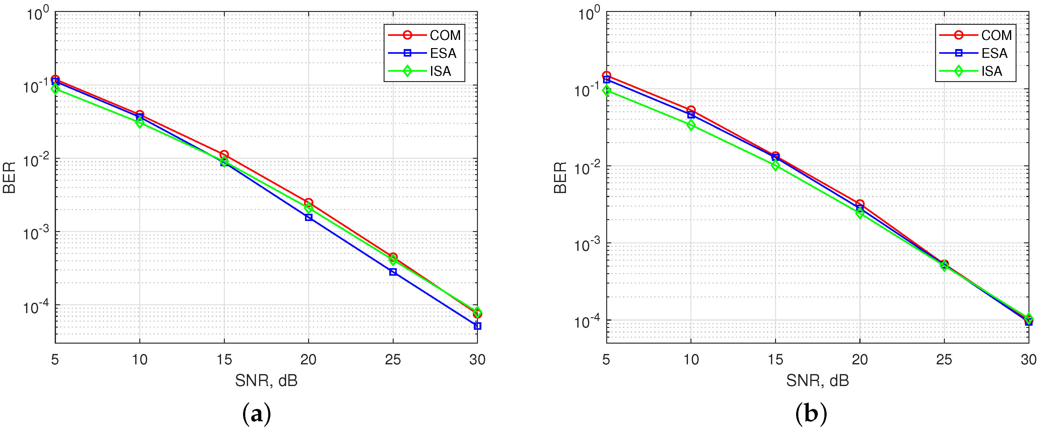
In Figure 7, BER performance of existing SMS-s and the ISA are simulated for synchronous communication, where all users arrive to the BS at the same time (). Figure 7a shows the results for OFDM-IM with . ESA mapper is superior to COM mapper as aforementioned. BER performance of ISA lies in between COM with (, ) and COM with (s, v) because of subblock division property. Therefore, the performance of ISA is the best for low signal-to-noise ratio (SNR). Its performance goes near to COM as SNR increases. In Figure 7b, obtained results are illustrated for . The performance of ESA is similar to COM [19].The performance of ISA is almost the same with ESA and COM for high SNR, while it outperforms for low SNR due to subblock division.
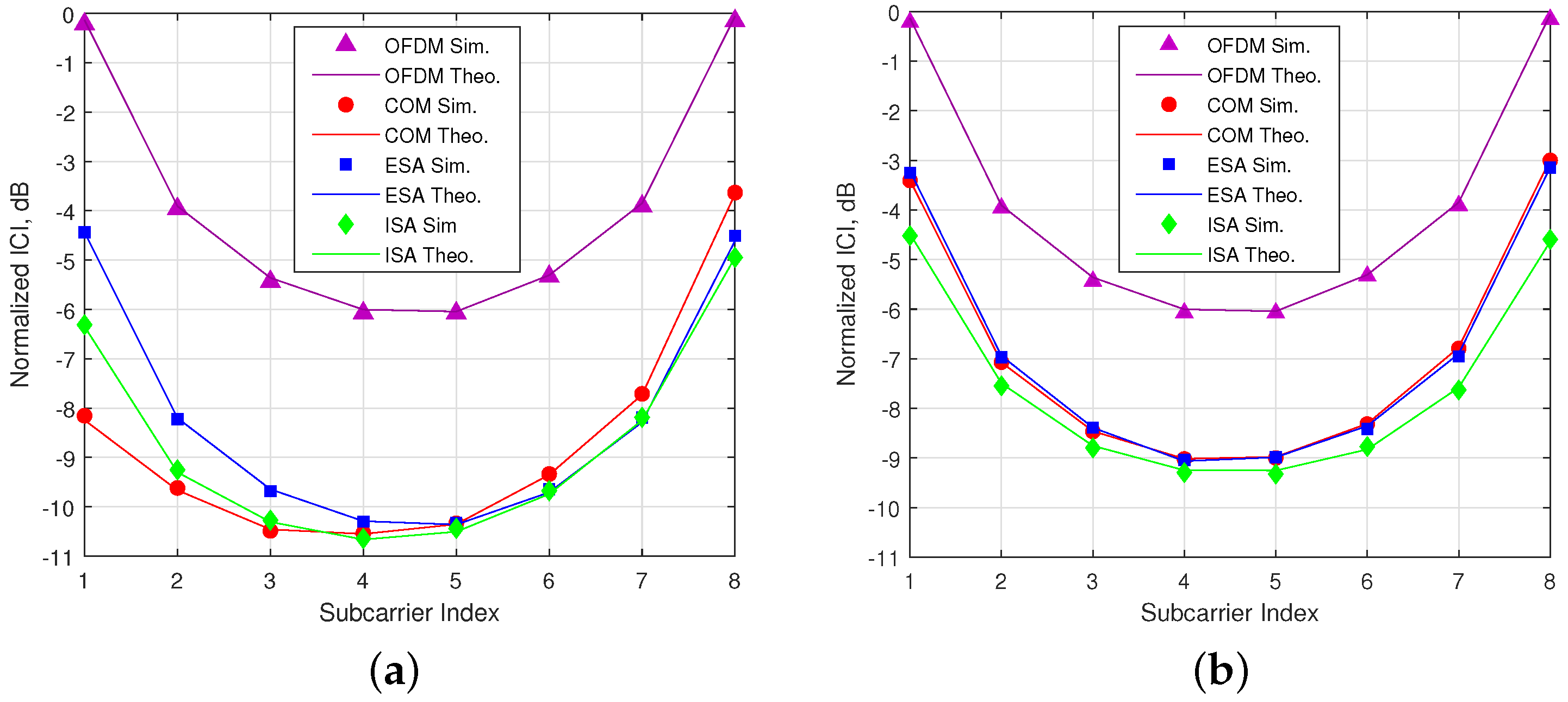
In Figure 8, it is shown that theoretical calculations of ICI for both OFDM-IM and conventional OFDM perfectly match with computer-based simulations. The simulation results are obtained under maximum time offset for 2-nd user, who has less power in comparison to others. As seen in the figure, OFDM-IM is exposed to less ICI thanks to partial subcarrier activation under asynchronous transmission. In the Figure 8a, the most exposed to ICI is ESA, since it has higher probability of edge subcarrier usage as shown in Figure 6a. COM experience minimum ICI for initial subcarriers due to lower usage probability of last subcarriers of the previous user. On the other hand, last subcarriers of subblock are exposed to maximum ICI due to higher usage probability of initial subcarriers of the following user. Proposed method ISA encounters less ICI because of its lower usage probability for edge subcarriers.The obtained ICI results are inversely proportional to the edge subcarrier usage probability within the subblock. According to activation probability for SMS-s with (, ) as in the Figure 6b, ISA faces minimum ICI, as illustrated in Figure 8b.
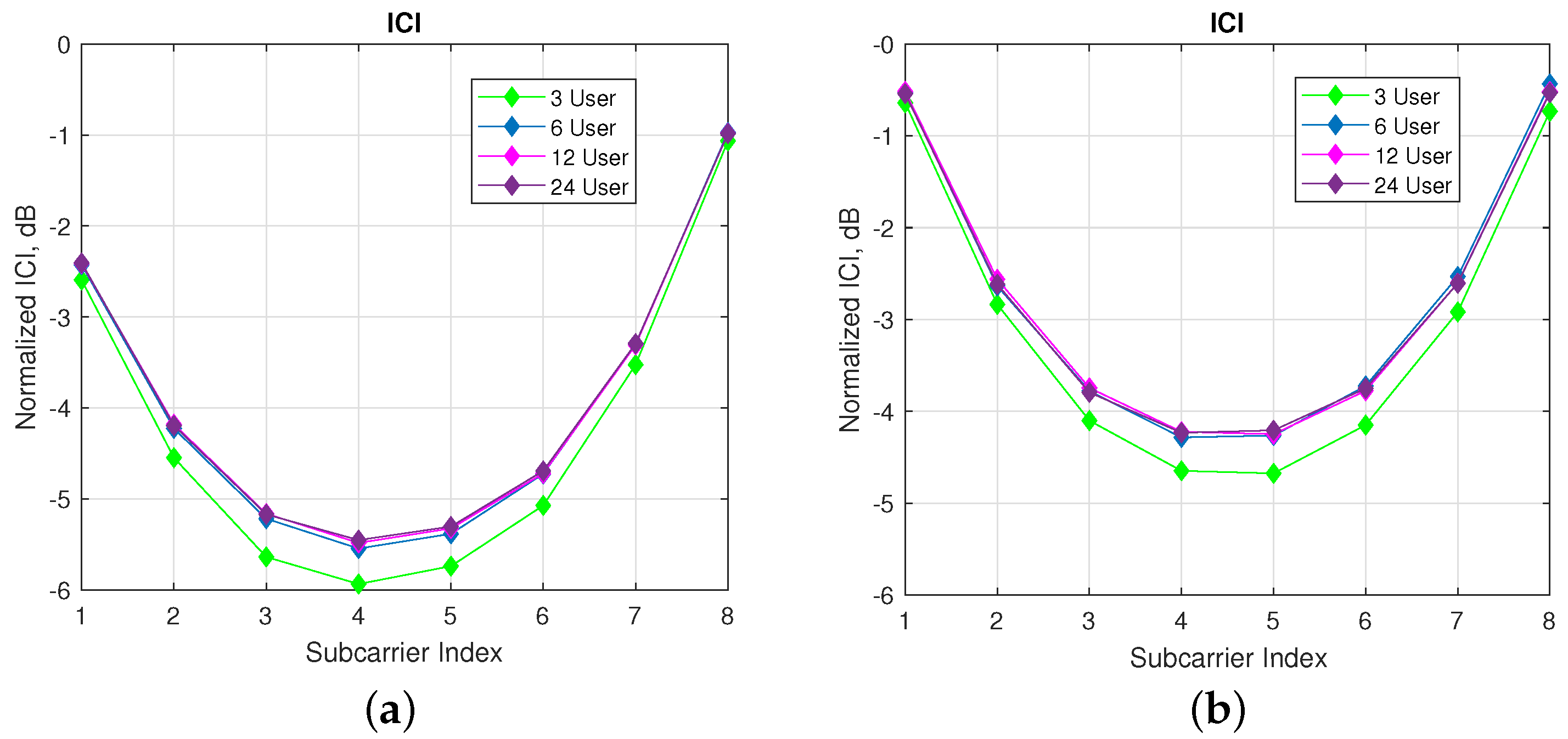
In Figure 9, ICI analyzes on reference user are performed regarding different number of machine users with a fixed number of subcarriers per user. As seen in the Figure 9a,b, nearly 0.5 dB more interference is observed for 6 users compared with 3 users case. For more than 6 users, there is a very slit increase in the ICI. Hence, the amount of the interference coming from far users proportionally decays with the increase in the number of users.
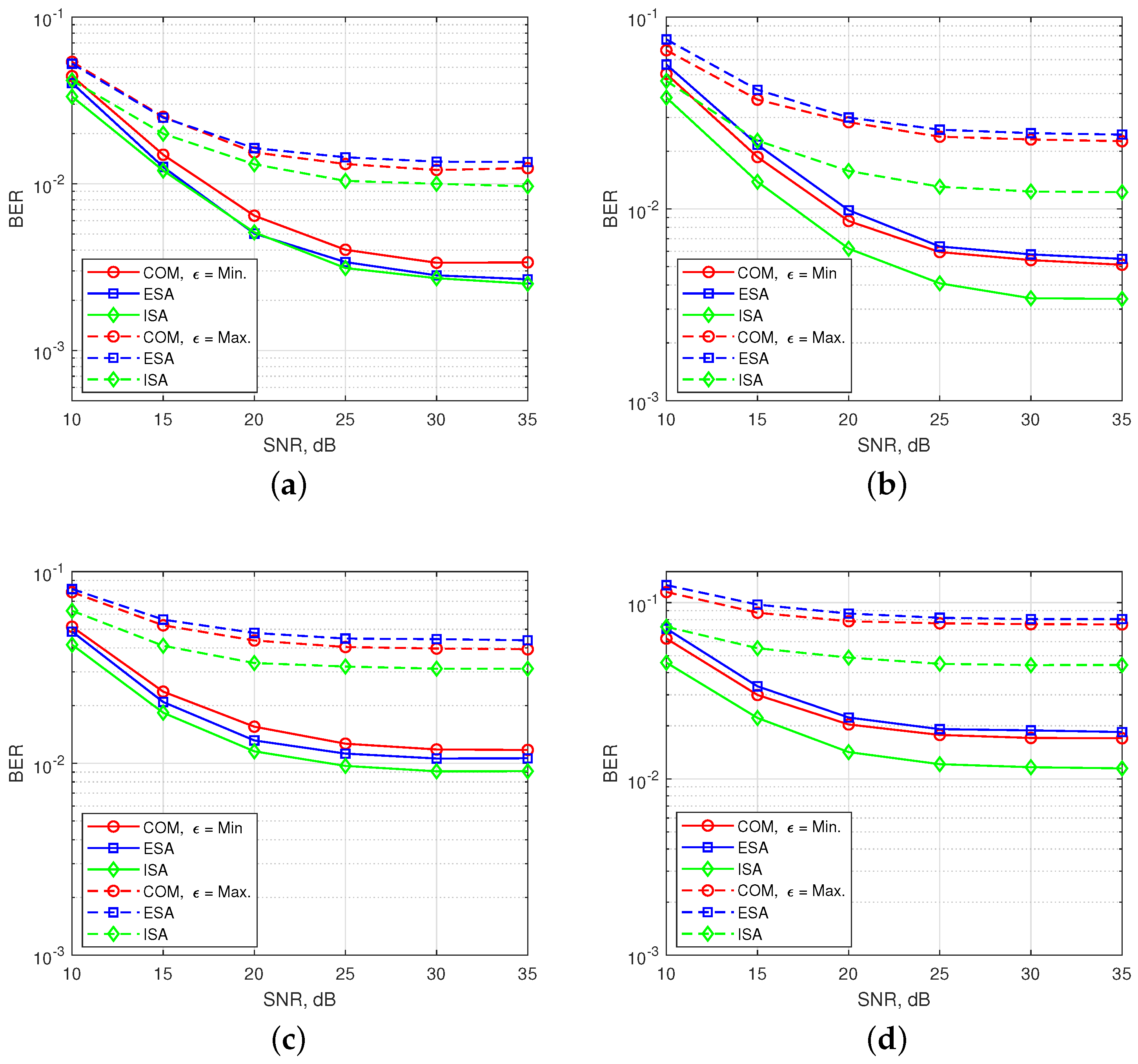
In Figure 10, BER performances are obtained for 2-nd user under time and power misalignment. In Figure 10a,b, only time misalignment between the users is considered. As seen in the Figure 10a, ISA with (, ) has the best BER performance, but with a slight difference from ESA for . Edge subcarrier activation probability for ESA is higher in comparison to COM and ISA, as shown in Figure 6. Therefore, ICI coming from adjacent users to the 2-nd user further increases for ESA. For , the difference between the performances of SMS-s is more obvious and ESA has the worst performance. COM has a slight better BER performance than ESA as observed in the Figure 8b. ISA offers a much better BER performance for maximum time misalignment, since it has the smallest edge subcarrier activation probability associated with the lowest ICI. In Figure 10b, OFDM-IM with subblock parameters (, ) is simulated. The performance of both ESA and COM become much worse than in Figure 10a. For ISA with (, ), subcarrier usage probability is more localized around the middle subcarriers than in the case of ISA with (, ), as shown in Figure 6. Moreover, equiprobable activation properties of ESA causes a destructive effect on the BER performance due to non-uniform distribution of ICI. For COM, less activation probability of one edge provides better protection against ICI caused by asynchronism between the users in time. In Figure 10c,d, power difference between the users is also considered as well as time offset. The advantages of ISA against asynchronous transmission impairments are much more visible with the increase of ICI. Not only power difference but also increased number of active subcarriers within the OFDM-IM subblock results in higher ICI. Therefore, ISA mapping scheme plays a key role for larger subcarrier activation ratio of in asynchronous mMTC networks.
6. Conclusions
One of the fundamental challenges for 5G and beyond technologies is to handle asynchronous impairments in uncoordinated mMTC networks. Performance of OFDM under time misalignment conditions is severely affected due to its susceptibility against ICI. Fractional subcarrier activation in OFDM-IM develops immunity to ICI caused by both time and power misalignments between the machine users. Flexible and adaptive structure of OFDM-IM provides opportunities to manage the active subcarriers. A novel subcarrier activation scheme ISA is proposed by considering the non-uniform distribution of ICI in asynchronous transmission. It offers the best performance in comparison to existing methods both COM and ESA without increasing the computational complexity. In addition, energy-free transmission through active subcarrier indices makes OFDM-IM technology a strong candidate for mMTC networks that require low energy consumption.
In this study, investigations are performed for OFDM-IM systems by considering asynchronous impact of mMTC networks. In order not to exceed the scope of this paper, OFDM-IM systems performance regarding other impacts of mMTC architecture is left for future studies. In the future work, we will consider both clustering users and conflicted users for mMTC. Moreover, optimization of OFDM-IM subblock size and activation ratio will be evaluated for different machine users with respect to their requirements.
Acknowledgments
The authors would like to thank Murat Karabacak from CoSINC and WCSP research groups for his help through obtaining and evaluating the results properly.
Author Contributions
Seda Doğan, Armed Tusha and Hüseyin Arslan conceived the study idea and developed the system model. Seda Doğan and Armed Tusha performed computer-based simulations and wrote the paper. Hüseyin Arslan supervised Seda Doğan and Armed Tusha during the development of the manuscript.
Conflicts of Interest
The authors declare no conflict of interest.
Abbreviations
The following abbreviations are used in this study:
| AWGN | Additive White Gaussian Noise |
| BS | Base Station |
| CFO | Carrier Frequecny Offset |
| COM | Combinatorial |
| CP | Cyclic Prefix |
| ESA | Equiprobable Subcarrier Activation |
| FBMC | Filter Bank Multi Carrier |
| FFT | Fast Fourier Transform |
| GFDM | Generalized Frequency Division Multiplexing |
| ICI | Inter-Carrier Interference |
| IFFT | Inverse-Fast Fourier Transform |
| IM | Index Modulation |
| ISA | Inner Subcarrier Activation |
| ISI | Inter Symbol Interference |
| LLR | Log-Likelihood Ratio |
| LUT | Look Up Table |
| MIMO | Multiple Input Multiple Output |
| ML | Maximum Likelihood |
| mMTC | Massive Machine-Type Communications |
| MUI | Multi User Interference |
| OFDM | Orthogonal Frequency Division Multiplexing |
| OFDM-IM | Orthogonal Frequency Division Multiplexing with Index Modulation |
| OOBE | Out-of-Band Emission |
| SA | Subblock Assignment |
| SNR | Signal to Noise Ratio |
| SM | Spatial Modulation |
| SMS | Subcarrier Mapping Scheme |
| TO | Time Offset |
| UFMC | Universal Filtered Multi-Carrier |
| V2X | Vehicle to X |
References
- Brake, D. 5G and Next Generation Wireless: Implications for Policy and Competition; Technical report; Information Technology & Innovation Foundation (ITIF): Washington, DC, USA, 30 June 2016. [Google Scholar]
- Wunder, G.; Jung, P.; Kasparick, M.; Wild, T.; Schaich, F.; Chen, Y.; Brink, S.T.; Gaspar, I.; Michailow, N.; Festag, A.; Mendes, L.; et al. 5G NOW: Non-orthogonal, asynchronous waveforms for future mobile applications. IEEE Commun. Mag. 2014, 52, 97–105. [Google Scholar] [CrossRef]
- Bockelmann, C.; Pratas, N.; Nikopour, H.; Au, K.; Svensson, T.; Stefanovic, C.; Popovski, P.; Dekorsy, A. Massive machine-type communications in 5G: Physical and MAC-layer solutions. IEEE Commun. Mag. 2016, 54, 59–65. [Google Scholar] [CrossRef]
- Yazar, A.; Arslan, H. A flexibility metric and optimization methods for mixed numerologies in 5G and beyond. IEEE Access 2018. accepted for publication. [Google Scholar] [CrossRef]
- Cordeschi, N.; Amendola, D.; Shojafar, M.; Baccarelli, E. Distributed and adaptive resource management in Cloud-assisted Cognitive Radio Vehicular Networks with hard reliability guarantees. Veh. Commun. 2015, 2, 1–12. [Google Scholar] [CrossRef]
- Wang, S.; Thompson, J.S.; Grant, P.M. Closed-form expressions for ICI/ISI in filtered OFDM systems for asynchronous 5G uplink. IEEE Trans. Commun. 2017, 65, 4886–4898. [Google Scholar] [CrossRef]
- Hwang, T.; Yang, C.; Wu, G.; Li, S.; Li, G.Y. OFDM and its wireless applications: A survey. IEEE Trans. Veh. Technol. 2009, 58, 1673–1694. [Google Scholar] [CrossRef]
- Muquet, B.; Wang, Z.; Giannakis, G.; de Courville, M.; Duhamel, P. Cyclic prefixing or zero padding for wireless multicarrier transmissions? IEEE Trans. Commun. 2002, 50, 2136–2148. [Google Scholar] [CrossRef]
- Demir, A.F.; Arslan, H. The Impact of Adaptive Guards for 5G and Beyond. In Proceedings of the 28th IEEE International Symposium on Personal, Indoor, and Mobile Radio Communications (PIMRC), Montreal, QC, Canada, 8–13 October 2017. [Google Scholar]
- Farhang-Boroujeny, B. OFDM versus filter bank multicarrier. IEEE Signal Process. Mag. 2011, 28, 92–112. [Google Scholar] [CrossRef]
- Wang, S.; Armstrong, J.; Thompson, J.S. Waveform performance for asynchronous wireless 5G uplink communications. In Proceedings of the IEEE 27th Annual International Symposium on Personal, Indoor, and Mobile Radio Communications (PIMRC), Valencia, Spain, 4–8 September 2016; pp. 1–6. [Google Scholar]
- Eeckhaute, M.V.; Bourdoux, A.; Doncker, P.D.; Horlin, F. Performance of emerging multi-carrier waveforms for 5G asynchronous communications. EURASIP J. Wirel. Commun. Netw. 2017, 2017, 29. [Google Scholar] [CrossRef]
- Weiss, T.; Hillenbrand, J.; Krohn, A.; Jondral, F. Mutual interference in OFDM-based spectrum pooling systems. In Proceedings of the IEEE 59th Vehicular Technology Conference, VTC, Milan, Italy, 17–19 May 2004. [Google Scholar]
- Soleimani, H.; Tomasin, S.; Alizadeh, T.; Shojafar, M. Cluster-head based feedback for simplified time reversal prefiltering in ultra-wideband systems. Phys. Commun. 2017, 25, 100–109. [Google Scholar] [CrossRef]
- Basar, E. Index modulation techniques for 5G wireless networks. IEEE Commun. Mag. 2016, 54, 168–175. [Google Scholar] [CrossRef]
- Mesleh, R.; Haas, H.; Sinanovic, S.; Ahn, C.W.; Yun, S. Spatial modulation. IEEE Trans. Veh. Technol. 2008, 57, 2228–2241. [Google Scholar] [CrossRef]
- Abu-alhiga, R.; Haas, H. Subcarrier-index modulation OFDM. In Proceedings of the IEEE 20th International Symposium on Personal, Indoor and Mobile Radio Communications (PIMRC), Tokyo, Japan, 13–16 September 2009. [Google Scholar]
- Basar, E.; Aygolu, U.; Panayirci, E.; Poor, H.V. Orthogonal frequency division multiplexing with index modulation. IEEE Trans. Signal Process. 2013, 61, 5536–5549. [Google Scholar] [CrossRef]
- Wen, M.; Zhang, Y.; Li, J.; Basar, E.; Chen, F. Equiprobable subcarrier activation method for OFDM with index modulation. IEEE Commun. Lett. 2016, 20, 2386–2389. [Google Scholar] [CrossRef]
- Cheng, X.; Wen, M.; Yang, L.; Li, Y. Index modulated OFDM with interleaved grouping for V2X communications. In Proceedings of the 17th International IEEE Conference on Intelligent Transportation Systems (ITSC), Qingdao, China, 8–11 October 2014; pp. 1097–1104. [Google Scholar]
- Ma, Q.; Yang, P.; Xiao, Y.; Bai, H.; Li, S. Error probability analysis of OFDM-IM with carrier frequency offset. IEEE Commun. Lett. 2016, 20, 2434–2437. [Google Scholar] [CrossRef]
- Ntouni, G.D.; Kapinas, V.M.; Karagiannidis, G.K. On the optimal tone spacing for interference mitigation in OFDM-IM systems. IEEE Commun. Lett. 2017, 21, 1019–1022. [Google Scholar] [CrossRef]
- Sahin, A.; Arslan, H. Edge windowing for OFDM based systems. IEEE Commun. Lett. 2011, 15, 1208–1211. [Google Scholar] [CrossRef]
- Sahin, A.; Bala, E.; Guvenc, I.; Yang, R.; Arslan, H. Partially overlapping tones for uncoordinated networks. IEEE Trans. Commun. 2014, 62, 3363–3375. [Google Scholar] [CrossRef]
Figure 1.
Subcarrier presentation in frequency domain for OFDM and OFDM-IM. Each color refers to a single subcarrier. (a) Three out of eight subcarriers are activated in OFDM-IM. (b) All of eight subcarriers are utilized in OFDM.
Figure 1.
Subcarrier presentation in frequency domain for OFDM and OFDM-IM. Each color refers to a single subcarrier. (a) Three out of eight subcarriers are activated in OFDM-IM. (b) All of eight subcarriers are utilized in OFDM.

Figure 2.
Uplink system model and user-subblock assignment methods: (a) interleaved; (b) localized. In frequency domain, each user’s band is shown with a different color. For a given user, filled bands represent used OFDM-IM subblock, which contains more than one subcarrier.
Figure 2.
Uplink system model and user-subblock assignment methods: (a) interleaved; (b) localized. In frequency domain, each user’s band is shown with a different color. For a given user, filled bands represent used OFDM-IM subblock, which contains more than one subcarrier.

Figure 3.
Baseband equivalent model of the uplink system by considering time offset between the users.
Figure 3.
Baseband equivalent model of the uplink system by considering time offset between the users.

Figure 4.
Block diagram of asynchronous OFDM-IM transmitter for i-th block of u-th user.

Figure 5.
(a) Time, frequency and power domain illustration of three users’ signals. Each user’s signal is shown by different color. (b) Time domain representation of the superimposed signal at the BS.
Figure 5.
(a) Time, frequency and power domain illustration of three users’ signals. Each user’s signal is shown by different color. (b) Time domain representation of the superimposed signal at the BS.

Figure 6.
Subcarrier usage probability within an OFDM-IM subblock for the three SMS-s regarding to different . (a) and . (b) and .
Figure 6.
Subcarrier usage probability within an OFDM-IM subblock for the three SMS-s regarding to different . (a) and . (b) and .

Figure 7.
BER performance of synchronous multi-user OFDM-IM regarding to the three SMS-s. (a) SMS-s with and . (b) SMS-s with and .
Figure 7.
BER performance of synchronous multi-user OFDM-IM regarding to the three SMS-s. (a) SMS-s with and . (b) SMS-s with and .

Figure 8.
ICI analysis for OFDM and OFDM-IM regarding to three SMS-s. (a) SMS-s with and . (b) SMS-s with and .
Figure 8.
ICI analysis for OFDM and OFDM-IM regarding to three SMS-s. (a) SMS-s with and . (b) SMS-s with and .

Figure 9.
ICI analysis for ISA SMS regarding to various number of machine users. (a) ISA SMS with and . (b) ISA SMS with and .
Figure 9.
ICI analysis for ISA SMS regarding to various number of machine users. (a) ISA SMS with and . (b) ISA SMS with and .

Figure 10.
BER performance of multi-user OFDM-IM regarding to three SMS-s. Only time offset between the machine users is considered for (a) and (b), while both time and power offset are considered for (c) and (d). (a) SMS-s with and . (b) SMS-s with and . (c) SMS-s with and . (d) SMS-s with and .
Figure 10.
BER performance of multi-user OFDM-IM regarding to three SMS-s. Only time offset between the machine users is considered for (a) and (b), while both time and power offset are considered for (c) and (d). (a) SMS-s with and . (b) SMS-s with and . (c) SMS-s with and . (d) SMS-s with and .


Table 1.
Symbol description used in the paper.
| Symbol | Description |
|---|---|
| Transmitted signal by u-th user | |
| Channel belongs to u-th user | |
| Time offset for u-th user | |
| Received Signal by u-th user | |
| N | OFDM-IM block size |
| G | Number of OFDM-IM subbblock |
| U | Number of machine users |
| Number subcarriers per user | |
| Number of subblocks per user | |
| s | OFDM-IM subblock size |
| v | Number of active subcarriers within a OFDM-IM subbblock |
| Indices of active subcarriers of u-th user for l-th subblock | |
| p | Number of bits per OFDM-IM subblock |
| Bit stream corresponds to active subcarriers for a OFDM-IM subblock | |
| Bit stream is mapped to M-ary symbols | |
| Number of transmitter per user | |
| i-th data block of u-th user | |
| Interference coming from to the | |
| Power difference between and | |
| ICI for u-th user |
Table 2.
Look-up table for .
| I | ||
|---|---|---|
| 00 | 1,2 | |
| 01 | 2,3 | |
| 10 | 3,4 | |
| 11 | 1,4 |
© 2018 by the authors. Licensee MDPI, Basel, Switzerland. This article is an open access article distributed under the terms and conditions of the Creative Commons Attribution (CC BY) license (http://creativecommons.org/licenses/by/4.0/).
Share and Cite
MDPI and ACS Style
Doğan, S.; Tusha, A.; Arslan, H. OFDM with Index Modulation for Asynchronous mMTC Networks. Sensors 2018, 18, 1280. https://doi.org/10.3390/s18041280
AMA Style
Doğan S, Tusha A, Arslan H. OFDM with Index Modulation for Asynchronous mMTC Networks. Sensors. 2018; 18(4):1280. https://doi.org/10.3390/s18041280
Chicago/Turabian StyleDoğan, Seda, Armed Tusha, and Hüseyin Arslan. 2018. "OFDM with Index Modulation for Asynchronous mMTC Networks" Sensors 18, no. 4: 1280. https://doi.org/10.3390/s18041280
Note that from the first issue of 2016, this journal uses article numbers instead of page numbers. See further details here.