A MEMS-based Air Flow Sensor with a Free-standing Micro-cantilever Structure

1
Department of Mechanical and Automation Engineering, Da-Yeh University, Changhua, Taiwan
2
Department of Architecture, National Cheng Kung University, Tainan, Taiwan 701
*
Author to whom correspondence should be addressed.
Sensors 2007, 7(10), 2389-2401; https://doi.org/10.3390/s7102389
Submission received: 27 August 2007
/
Accepted: 10 October 2007
/
Published: 17 October 2007
(This article belongs to the Special Issue Cantilever, Microcantilevers and Nanocantilever Sensors and Biosensors)
Abstract
:This paper presents a micro-scale air flow sensor based on a free-standing cantilever structure. In the fabrication process, MEMS techniques are used to deposit a silicon nitride layer on a silicon wafer. A platinum layer is deposited on the silicon nitride layer to form a piezoresistor, and the resulting structure is then etched to create a freestanding micro-cantilever. When an air flow passes over the surface of the cantilever beam, the beam deflects in the downward direction, resulting in a small variation in the resistance of the piezoelectric layer. The air flow velocity is determined by measuring the change in resistance using an external LCR meter. The experimental results indicate that the flow sensor has a high sensitivity (0.0284 Ω/ms-1), a high velocity measurement limit (45 ms-1) and a rapid response time (0.53 s).
1. Introduction
Flow measurement is a necessary task in such diverse fields as medical instrumentation, process control, environmental monitoring, and so forth. Many previous studies have demonstrated the successful application of MEMS techniques to the fabrication of a variety of flow sensors capable of detecting both the flow rate and the flow direction [1-15]. Broadly speaking, MEMS-based gas flow sensors can be categorized as either thermal or non-thermal, depending upon their mode of operation.
Many thermally-actuated gas flow sensors employ some form of resistor to evaluate local temperature changes [1-6]. In such sensors, the temperature difference between the sensing resistors varies as the gas flow rate changes, and the resulting change in resistance enables the gas flow rate to be precisely determined. Qiu et al. [1] presented a micro gas-flow sensor featuring a heat sink and a flow guide on the underside of the sensing element, and showed that the device had a power consumption of 8 mW and was capable of measuring flow velocities of up to 5 ms-1. Neda et al. [2] fabricated a single-wire-type thermal flow sensor incorporating a polysilicon micro-heater, and demonstrated that the device had a broad measurement range of 0.005-35 ms-1, a rapid response time of just 0.14 ms (90%), and a power consumption of 6 mW. Mailly et al. [5] developed a flow sensor featuring a hot platinum thin film (3000 Å) deposited on a SiNx membrane (5000 Å). The response time and measurement range of the sensor were shown to be 6 ms and 0-20 ms-1, respectively, while the power consumption was of the order of 20 mW. Kim et al. [6] presented a micromachined circular-type thermal flow sensor capable of the simultaneous detection of both the flow rate and the flow direction. However, the power consumption of the device exceeded 80 mW. In recent years, an increasing number of non-thermal flow sensors have been developed. Typically, such devices have the advantages of a lower power consumption and an improved potential for integration with other sensors. Svedin et al. [8] fabricated a static turbine flow sensor featuring a micromachined silicon torque sensor. Although the proposed design eliminated the requirement for micro-heaters and therefore resulted in a low power consumption, the assembly process was complex, and hence the fabrication costs were high. Su et al. [9] developed a piezoresistive-type flow sensor with a silicon cantilever probe, in which the gas flow was measured by a strain gauge attached to the root of the cantilever beam. While the fabrication of the flow sensor was straightforward, the maximum measurable flow rate was of the order of just 20 ms-1, and hence the practicality of the device for flow rate sensing applications characterized by flow rates as high as 40 ms-1 was severely limited.
In a previous study [16], the current group presented a simple and reliable method for fabricating micro-cantilevers for humidity sensing applications. In the current study, a similar approach is employed to fabricate a flow sensor in which a piezoresistor is deposited on a free-standing micro-cantilever structure and connected to an LCR meter via gold electrodes. When air flows over the surface of the cantilever structure, the beam deforms slightly, causing a measurable change in the resistance of the piezoresistor layer from which the gas flow rate can then be inversely derived. The proposed sensor can be manufactured with a simplified and cheap fabrication process for measuring high flow rates.
2. Design
2.1. Sensing principle
In this study, the cantilever deflection by air flow can be obtained by combining the effects of the loads acting separately:
where δt is the total deflection of the cantilever, q is the uniform load intensity on the beam part, E is the Young's modulus of cantilever, I is the moment of inertia, L is the length of the cantilever, F is the concentrated load on the paddle part, a is the distance from the fixed end to the uniform load and b is the distance from the fixed end to the concentrated load [17]. Please note that q (the uniform load intensity) and F (the concentrated load) are applied by the wind pressure calculated by the Bernoulli's Eq.:
where Pwind is the wind pressure, ρair is the intensity of the air and Vwind is the air flow velocity.
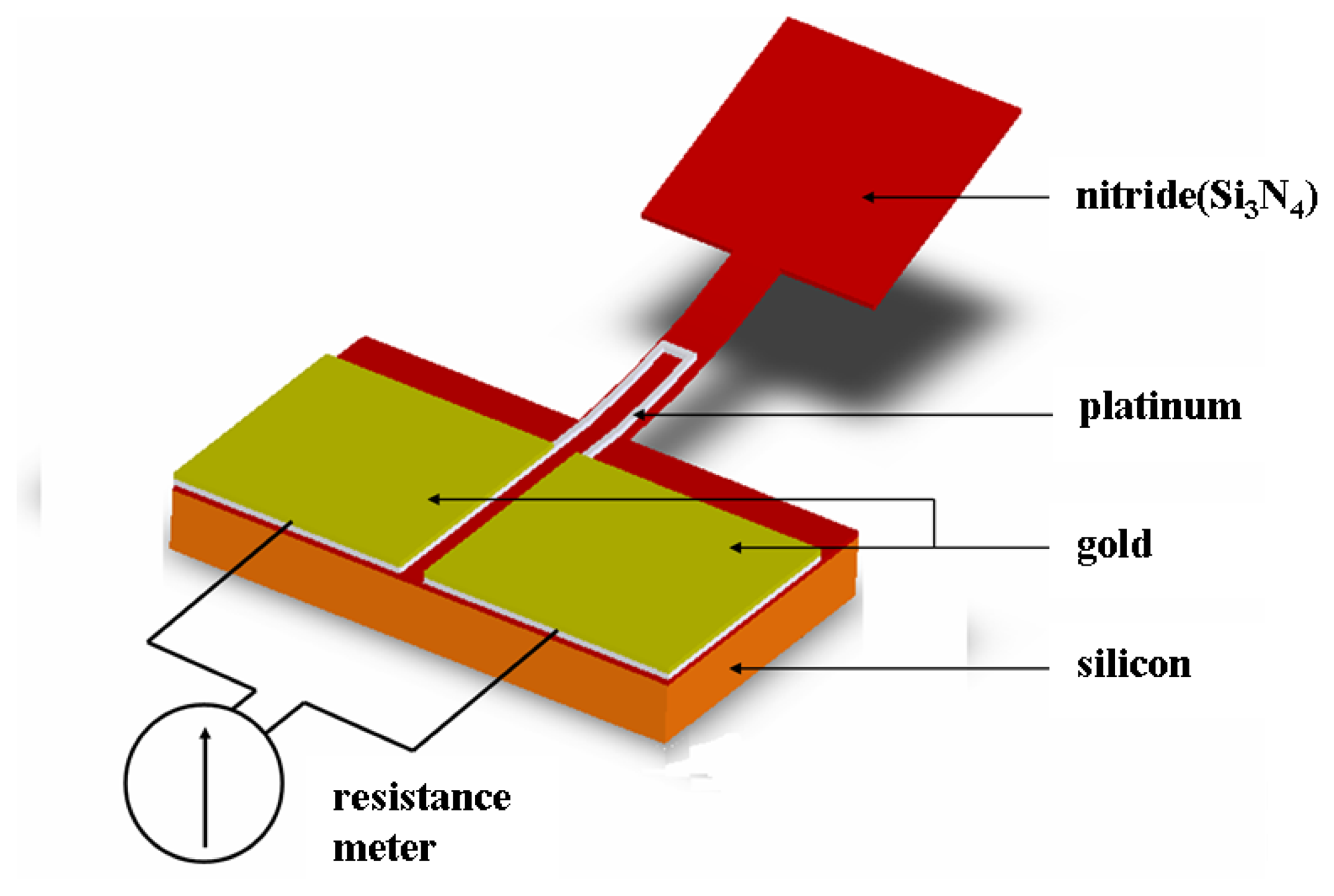
Due to the limit of the available manufacturing equipment, the airflow velocity is determined by measuring the change in resistance of the platinum pizeoresistor as the cantilever beam deflects under the influence of a gas flow passing over its surface. As shown in Figure 1, the electrodes used to connect the piezoresistor to the external LCR meter are fabricated from gold since gold has a lower resistivity than platinum, and hence the resistance effect of the leads is reduced. The resistance R of the piezoresistor is given by
where lR is the resistor length, ρ is the resistivity, A is the cross-sectional area, w is the width and t is thickness. The derivative of Eq. (3) is
where defines
, dl = Δl, dw = Δw and dt = Δt,
where v is poission's ratio.
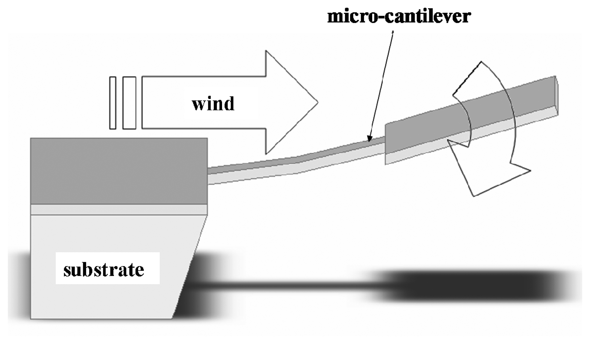
As shown in Figure 2, when air flows over the cantilever structure, the beam is deflected in the downward direction causing a change in the cross-sectional area, and hence the resistance, of the platinum resistor. The corresponding airflow velocity can then be determined simply by measuring the resistance change using the external LCR meter.
2.2. Cantilever beam dimensions
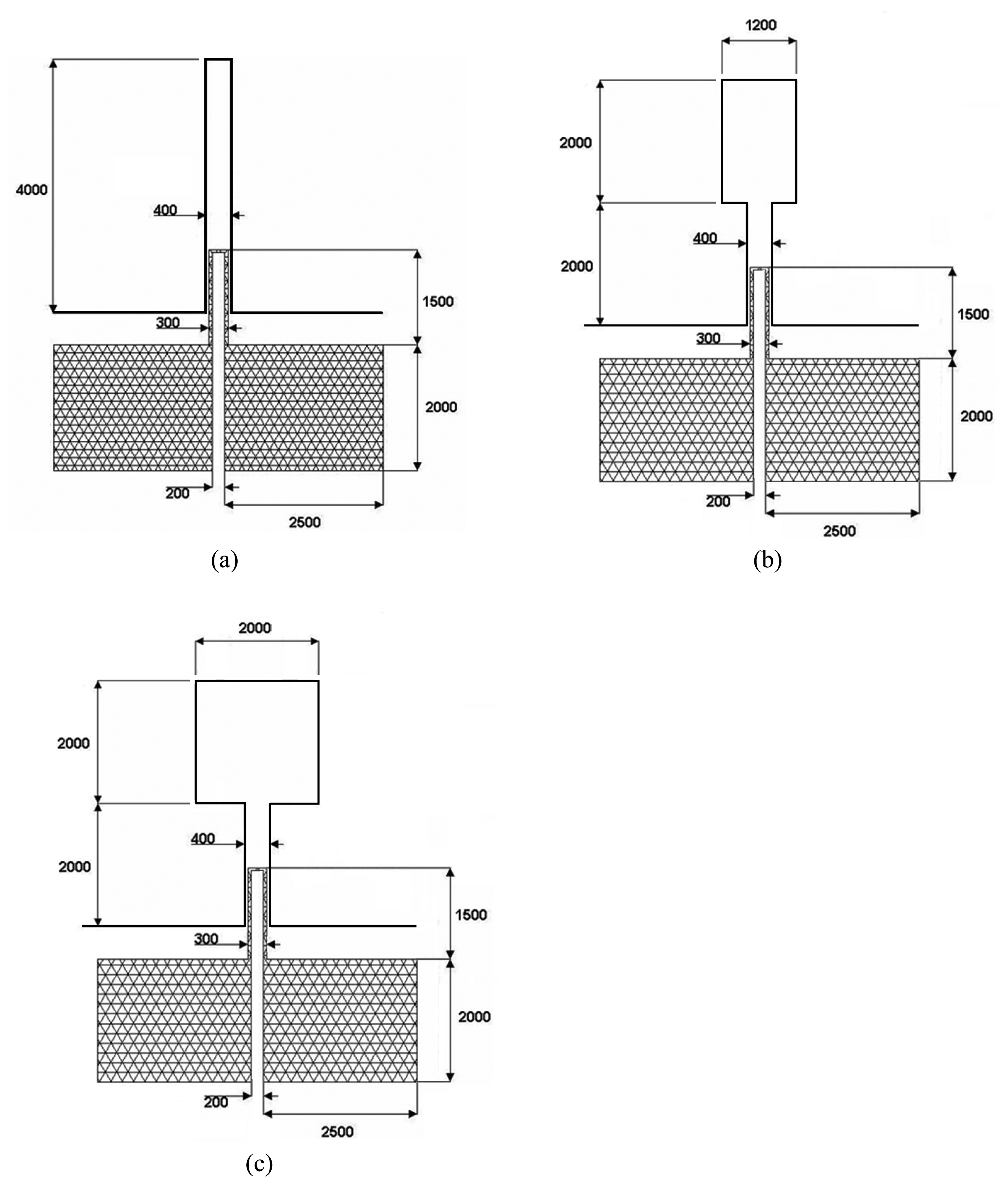
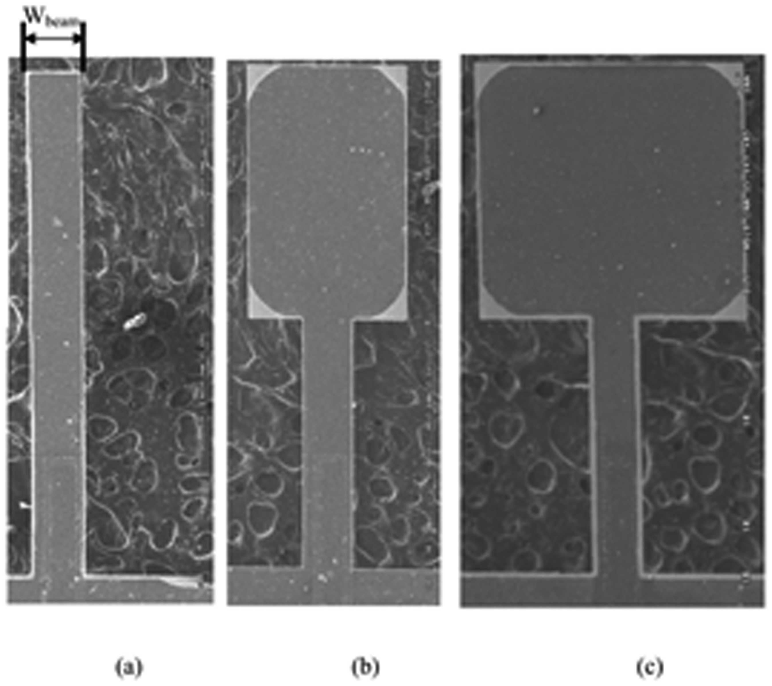
To investigate the relationship between the sensitivity of the proposed flow sensor and the physical dimensions of the cantilever structure, three different cantilever beam widths (Wbeam) were considered, namely 400 μm, 1200 μm and 2000 μm, respectively. As shown in Figure 3, the platinum piezoresistor had a length of 1500 μm in every case. Note that in this figure, the black crosshatched areas denote the platinum resistor, while the black lines indicate the periphery of the cantilever structure.
2.3. Cantilever deflection induced by thermal stress
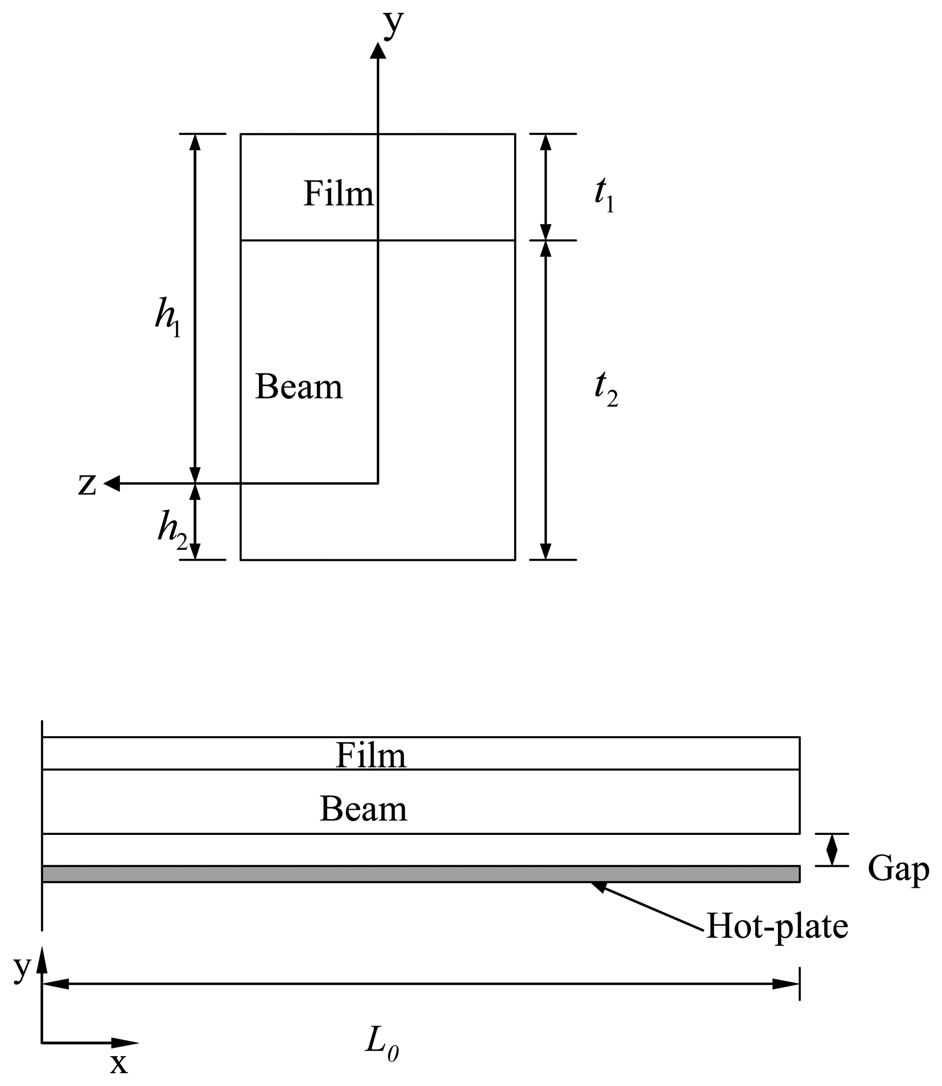
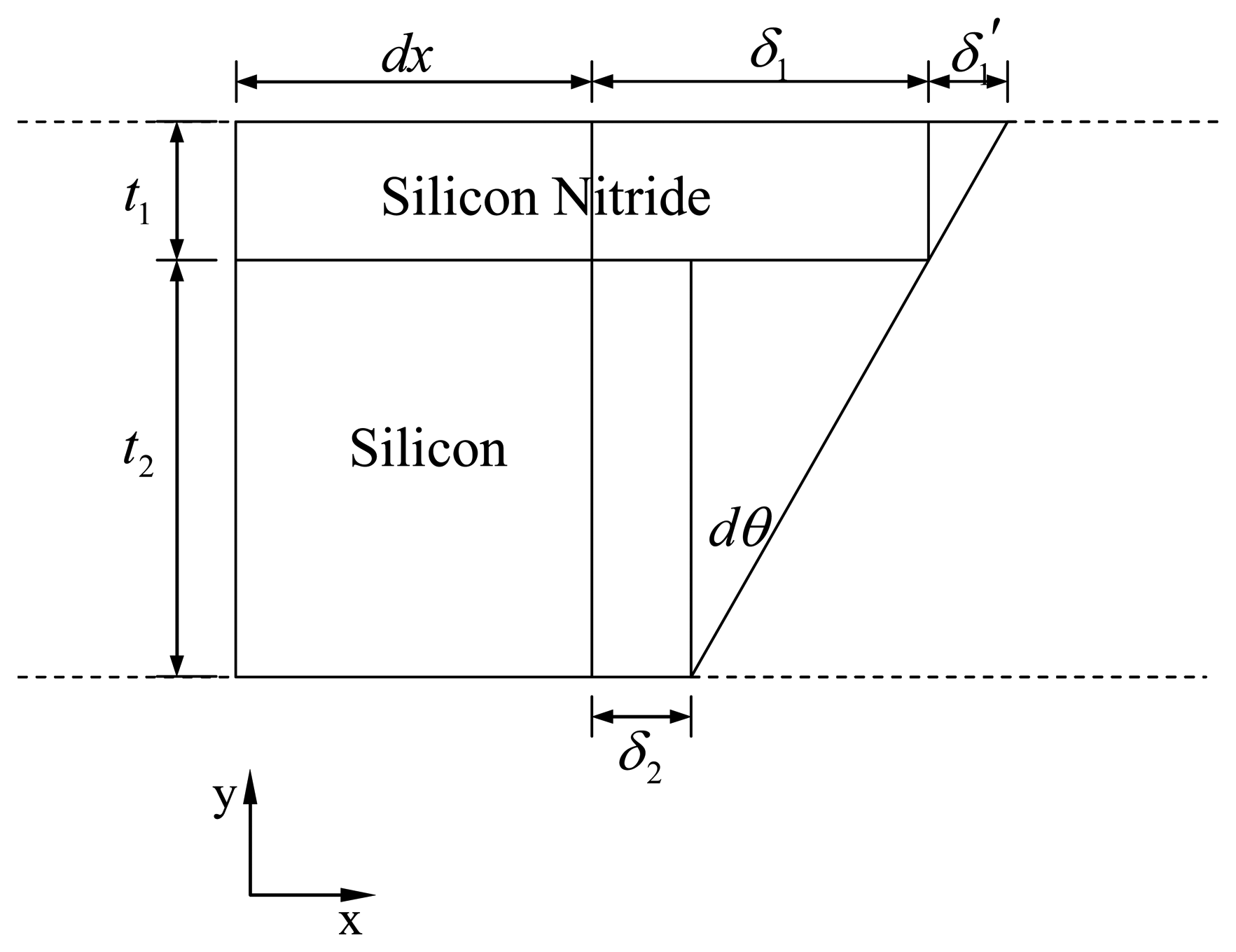
A schematic illustration of the current bimorph micro-cantilever is shown in Figure 4 [18]. In the current study, a thin film of silicon nitride is deposited on a silicon beam. In the model shown in Figure 4, the thicknesses of the film and beam are denoted as t1 and t2, respectively. When the micro-cantilever is subjected to thermal loading, the mismatch between the thermal expansion coefficients of the two components induces different thermal deformations of them and this causes residual stresses to be generated within the structure. A schematic diagram of the deformed micro-cantilever is shown in Figure 5 [18]. The relationship between the micro-cantilever displacement and the film and beam thicknesses is given approximately by
where δ1 and δ2 are the displacements of the film and beam caused by thermal expansion. From the geometrical similarity in Figure 5, it can be shown that the relationship among δ1, δ2, t1, and t2 is given by
Substituting eq. (7) and the relationships δ1 = α1ΔT dx and δ2 = α2ΔT dx into Equation (6) yields
where △T is the temperature rise and α1 and α2 are the coefficients of thermal expansion of the film and beam, respectively. The coefficients of thermal expansion of the electrode, film and beam are 9.1 E-6, 3.0 E-5 and 4.1 E-6, respectively. Equation (8) can be rewritten as
The equations of the micro-cantilever slope, θ, and deflection, v, can be obtained by integrating eq. (9) once and twice, respectively, i.e.,
Under these boundary conditions, the constants C1 and C2 must therefore also be equal to zero. The deflection at the free end of the beam, δ, can then be calculated from
where L is the length of the micro-cantilever [18].
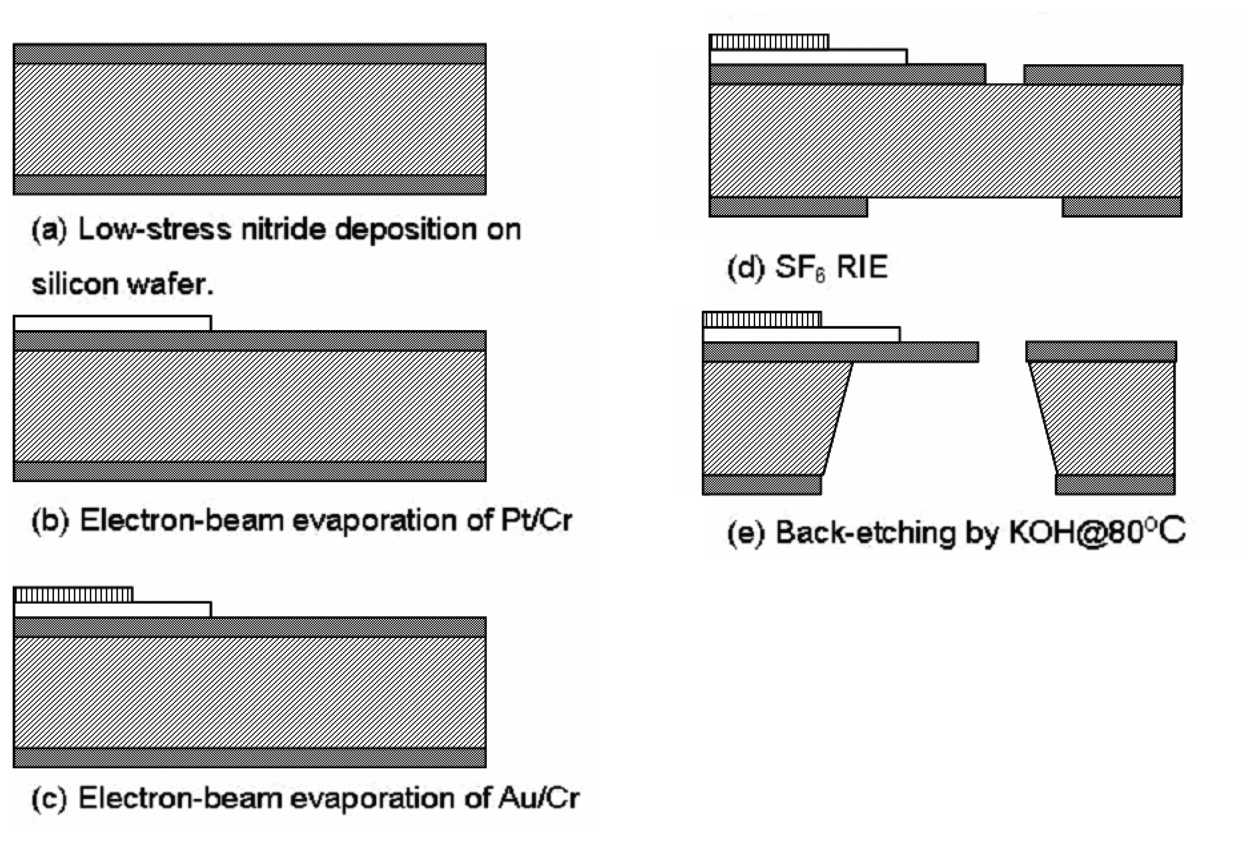
3. Fabrication
Figure 6 presents a schematic overview of the fabrication process employed to create the freestanding micro-cantilever beam and platinum piezoresistor. The fabrication procedure commenced by depositing a 1.0 μm low-stress nitride layer on either side of a silicon wafer of thickness 500 μm using a low-pressure chemical vapor deposition process. Using an electron-beam evaporation process, a thin (0.02 μm) chromium adhesion layer was deposited on the nitride layer followed by a platinum layer with a thickness of 0.1 μm. The same deposition technique was then used to deposit an Au layer of thickness 0.4 μm on top of the platinum layer to connect the piezoresistor to the external LCR meter. The freestanding micro-cantilever structure was created by patterning the upper and lower nitride layers using SF6 RIE plasma and then releasing the structure by performing a back-etching process using a KOH etchant (30 wt%, 80 °C) with the front face of the wafer shielded using a Teflon protector.
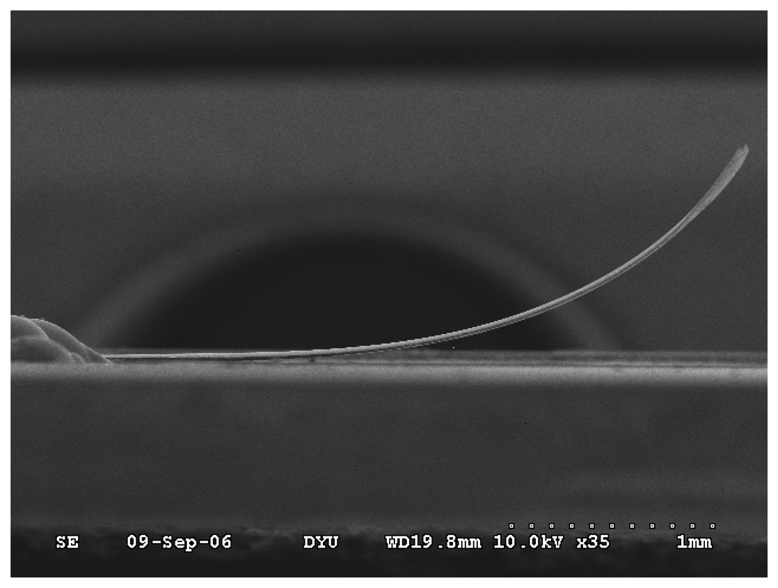
Following the etching process, it was observed that all three cantilevers exhibited an upward bending tendency due to the residual stress released during the fabrication process, as shown in the SEM images presented in Figure 7 and 8. In this study, the thermal fabrication process directly affects the residual stress of the cantilever. Therefore, it is controlled by accurate fabrication steps and parameters [16, 18].
4. Results and Discussion
A systematic investigation was performed to characterize the three air flow sensors. The tests were performed under ambient temperature conditions (25°C) in a wind tunnel at airflow velocities ranging from 0∼45 ms-1. The variation in the sensor resistance was measured using an LCR meter (WK4230, Wayne Kerr Electronics Ltd.). For reference purposes, the airflow velocity was also measured using a Pitot tube flow sensor in the wind tunnel. The power of the proposed sensors only consumes that of the LCR meter (0.15 mW), which is much less than the hot wire type of flow sensors.
4.1. Sensitivity of gas flow sensors
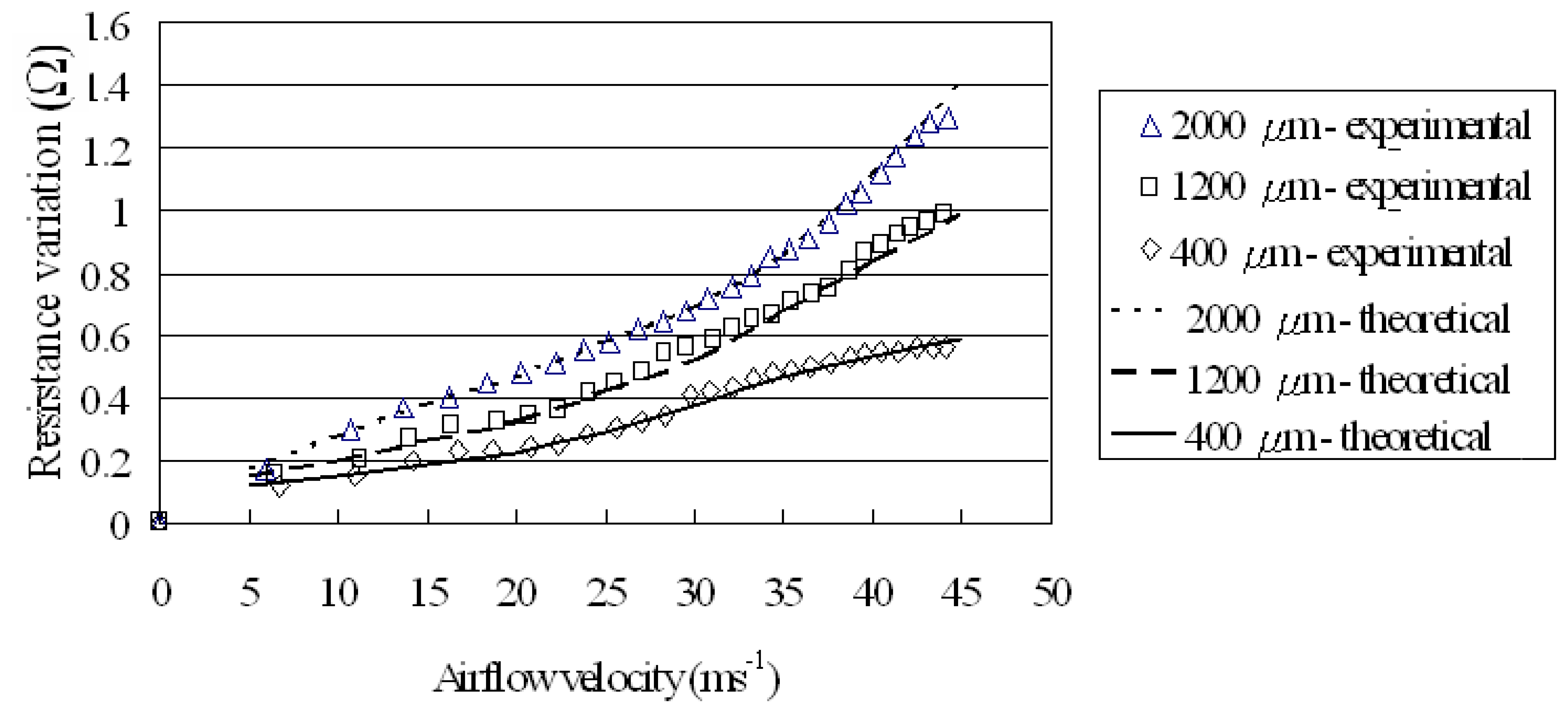
As shown in Figure 9, the resistance signal generated by the three flow sensors increases approximately linearly with an increasing airflow velocity. From inspection, the average sensitivities of the sensors with cantilevers of width (Wbeam) 400 μm, 1200 μm and 2000 μm are found to be 0.0134, 0.0227 and 0.0284 (Ω/ms-1), respectively, with a maximum error of 2%. In other words, the flow rate sensitivity increases as the width of the cantilever beam is increased. The experimental results also reveal that the maximum detectable flow rate is 45 ms-1. The theoretical results are shown in the same figure and it is found that both the experimental and theoretical results are of high correspondence.
The proposed flow sensor can be operated under the wind coming from the opposite direction in Figure 2, but the measurement range is reduced to be below 30ms-1 due to the cantilever structure fracture. Please note that to avoid undergoing torsion deformation and producing the erratic output problem of the piezoresistors, the flow sensors can only measure air flow that is directly along the axis of the cantilever.
It can also be found that due to the limits of the energy conversion between the kinetic energy of the air flow and the heat and the delay of the heat transfer on the thermal types of flow sensors, the current non-thermal type of flow sensor can measure higher flow rates because of its direct piezoresistor deformation caused by the kinetic energy of the air flow.
4.2. Time response of flow sensors
The response time of thermal flow sensors is known to vary from 0.14 ms to 150 ms [1-2]. It is also essential to investigate this performance in non-thermal type flow sensors. Figures 10, 11 and 12 reveal that the time responses of the sensors with cantilevers of width 400 μm, 1200 μm and 2000 μm are 1.38, 0.99 and 0.53 s (90%), respectively. In other words, the response time of the flow sensors decreases as the cantilever beam width is increased.
4.3. Stability of flow sensors
The experimental results indicate that at a constant flow rate of 30 ms-1 and a temperature of 25 °C, the variation in stability of the three flow sensors is found to be 0.0275%, 0.0346% and 0.0450% for cantilever tip width (Wbeam) of 400 μm, 1200 μm and 2000 μm, respectively. As shown the experimental data, the sensors stability decreases with an increasing cantilever tip width. It is clear to know the increasing cantilever tip width not only can enhance the flow sensor sensitivity but also decrease the response time. However, it may cause the flow sensor stability to be reduced. The resonant frequencies of the cantilevers are estimated to be 17.3 kHz, 8.7 kHz and 5.8 kHz, which are far above the possible environmental activation frequency.
5. Conclusions
Advances in MEMS techniques now make possible the fabrication of sophisticated sensors for a diverse range of applications. Compared to their traditional counterparts, micro-scale sensors have a greater sensitivity, a lower cost, an improved portability and a more straightforward integration with IC circuit devices. Of the various domains in which micro-sensors are deployed, flow rate sensing is one of the most common. Accordingly, the current study has developed a MEMS-based air flow sensor featuring a free-standing micro-cantilever structure. In the sensing operation, the air flow velocity is detected by measuring the change in resistance of a piezoelectric layer deposited on a cantilever beam as the beam deforms under the effect of the passing air flow. The experimental results have shown that the flow sensor has a high sensitivity (0.0284 Ω/ms-1), a high velocity measurement limit (45 ms-1) and a rapid response time (0.53 s).
Acknowledgments
The authors gratefully acknowledge the financial support provided to this study by the National Science Council of Taiwan under Grant N°s (NSC 96-2221-E-212-037 and NSC 95-2218-E-006-022).
References and Notes
- Qiu, L.; Hein, S.; Obermeier, E.; Schubert, A. Micro gas-flow sensor with integrated heat sink and flow guide. Sensors and Actuators A 1996, 54, 547–551. [Google Scholar]
- Neda, T.; Nakmura, K.; Takumi, T. A polysilicon flow sensor for gas flow meters. Sensors and Actuators A 1996, 54, 626–631. [Google Scholar]
- Makinwa, K.A.A.; Huijsing, J.H. A wind-sensor interface using thermal sigma delta modulation techniques. Sensors and Actuators A 2001, 92, 280–285. [Google Scholar]
- Matova, S.P.; Makinwa, K.A.A.; Huijsing, J.H. Compensation of packaging asymmetry in a 2-D wind sensor. IEEE Sensors Journal 2003, 3, 761–765. [Google Scholar]
- Mailly, F.; Giani, A.; Bonnot, R.; Temple-Boyer, P.; Pascal-Delannoy, F.; Foucaran, A.; Boyer, A. Anemometer with hot platinum thin film. Sensors and Actuators A 2001, 94, 32–38. [Google Scholar]
- Kim, S.; Nam, T.; Park, S. Measurement of flow direction and velocity using a micromachined flow sensor. Sensors and Actuators A 2004, 114, 312–318. [Google Scholar]
- Poghossian, A.; Yoshinobu, T.; Schöning, M. J. Flow-velocity microsensors based on semiconductor field-effect structures. Sensors 2003, 3, 202–212. [Google Scholar]
- Svedin, N.; Stemme, E.; Stemme, G. A static turbine flow meter with a micromachined silicon torque sensor. Journal of Microelectromechanical Systems 2003, 12, 937–946. [Google Scholar]
- Su, Y.; Evans, A.G.R.; Brunnschweile, A.; Ensell, G. Characterization of a highly sensitive ultra-thin piezoresistive silicon cantilever probe and its application in gas flow velocity sensing. J. Micromech. Microeng 2002, 12, 780–785. [Google Scholar]
- Wu, J.; Zhou, Q.; Liu, J.; Lou, Z. Simulation study of nano aqueous flow sensor based on amperometric measurement. Sensors 2006, 6, 473–479. [Google Scholar]
- Gundogdu, S.; Sahin, O. E.M.I. effects of cathodic protection on electromagnetic flowmeters. Sensors 2007, 7, 75–83. [Google Scholar]
- Nguyen, N. T. Micromachined flow sensors – a review. Flow Meas. Instrum. 1997, 8, 7–16. [Google Scholar]
- Neuzil, P.; Sridhar, U.; llic, B. Air flow actuation of micromechanical oscillators. Applied Physics Letters 2001, 79, 138–140. [Google Scholar]
- Putten, V.; Middelhoek, S. Integrated silicon anemometer. Electronics Letters 1974, 10, 425–426. [Google Scholar]
- Wang, X.; Qian, J.; Zhang, D. Design, fabrication, testing and mechanical analysis of bulk-micromachined flowmeters. ACTC Mechanica Sinica 2004, 20, 152–158. [Google Scholar]
- Lee, C.Y.; Lee, G.B. Micromachine-based humidity sensors with integrated temperature sensors for signal drift compensation. J. Micromech. Microeng 2003, 13, 620–627. [Google Scholar]
- Gere, J.M. Mechanics of Materials, 5th Ed. ed; Nelson Thornes Ltd: United Kingdom, 2002; pp. 887–888. [Google Scholar]
- Lee, C.Y.; Tsai, C.H.; Chen, L.W.; Fu, L.M.; Chen, Y.C. Elastic-plastic modeling of heat-treated bimorph micro-cantilevers. Microsystem Technologies 2006, 12, 979–986. [Google Scholar]
Figure 1.
Schematic illustration of gas flow sensor.

Figure 2.
Diagram of gas flow sensor during sensing operation.

Figure 3.
Dimensions of cantilever beams with different tip widths. (a) Wbeam = 400 μm, (b) Wbeam = 1,200 μm and (c) Wbeam = 2,000 μm.
Figure 3.
Dimensions of cantilever beams with different tip widths. (a) Wbeam = 400 μm, (b) Wbeam = 1,200 μm and (c) Wbeam = 2,000 μm.

Figure 4.
Geometrical model of bimorph micro-cantilever [18].
Figure 4.
Geometrical model of bimorph micro-cantilever [18].

Figure 5.
Schematic diagram of deformed micro-cantilever [18].
Figure 5.
Schematic diagram of deformed micro-cantilever [18].

Figure 6.
Overview of fabrication process employed for proposed gas flow sensor.

Figure 7.
Side view SEM image of cantilever beam.

Figure 8.
SEM images of cantilever beams. (a) Wbeam = 400 μm, (b) Wbeam = 1,200 μm and (c) Wbeam = 2,000 μm.
Figure 8.
SEM images of cantilever beams. (a) Wbeam = 400 μm, (b) Wbeam = 1,200 μm and (c) Wbeam = 2,000 μm.

Figure 9.
Experimental and simulated result comparisons of flow rate sensitivity for sensors with cantilever tip widths of: (a) Wbeam = 400 μm [◊], (b) Wbeam = 1,200 μm [□] and (c) Wbeam = 2,000μm [∆].
Figure 9.
Experimental and simulated result comparisons of flow rate sensitivity for sensors with cantilever tip widths of: (a) Wbeam = 400 μm [◊], (b) Wbeam = 1,200 μm [□] and (c) Wbeam = 2,000μm [∆].

Figure 10.
Time response of gas flow sensor with cantilever tip widths of Wbeam = 400 μm for gas flow rate range of 0 to 30 ms-1.
Figure 10.
Time response of gas flow sensor with cantilever tip widths of Wbeam = 400 μm for gas flow rate range of 0 to 30 ms-1.

Figure 11.
Time response of gas flow sensor with cantilever tip widths of Wbeam = 1,200 μm for gas flow rate range of 0 to 30 ms-1.
Figure 11.
Time response of gas flow sensor with cantilever tip widths of Wbeam = 1,200 μm for gas flow rate range of 0 to 30 ms-1.

Figure 12.
Time response of gas flow sensor with cantilever tip widths of Wbeam = 2,000 μm for gas flow rate range of 0 to 30 ms-1.
Figure 12.
Time response of gas flow sensor with cantilever tip widths of Wbeam = 2,000 μm for gas flow rate range of 0 to 30 ms-1.

© 2007 by MDPI ( http://www.mdpi.org). Reproduction is permitted for noncommercial purposes.
Share and Cite
MDPI and ACS Style
Wang, Y.-H.; Lee, C.-Y.; Chiang, C.-M. A MEMS-based Air Flow Sensor with a Free-standing Micro-cantilever Structure. Sensors 2007, 7, 2389-2401. https://doi.org/10.3390/s7102389
AMA Style
Wang Y-H, Lee C-Y, Chiang C-M. A MEMS-based Air Flow Sensor with a Free-standing Micro-cantilever Structure. Sensors. 2007; 7(10):2389-2401. https://doi.org/10.3390/s7102389
Chicago/Turabian StyleWang, Yu-Hsiang, Chia-Yen Lee, and Che-Ming Chiang. 2007. "A MEMS-based Air Flow Sensor with a Free-standing Micro-cantilever Structure" Sensors 7, no. 10: 2389-2401. https://doi.org/10.3390/s7102389