1. Introduction
Coal resources play a supporting role in China’s economic development [
1,
2,
3], and they are also important for Poland and other countries [
4]. The support of surrounding rock is a basic protection of underground mining excavations [
5,
6,
7], but the problem of surrounding rock control in the goaf-side roadway is one of the major technical challenges that restricts underground coal mines [
8,
9,
10]. With the prolongation of mine service periods and deterioration of mining conditions, the complexity and support difficulty of such a goaf-side roadway continues to be upgraded, resulting in severe shrinkage and deformation of the roadways, increased maintenance costs, and frequent repair work, all of which seriously affect the normal mine production. The breakage of overlying strata and caving disturbances are the key cause of the surrounding rock structure instability of the goaf-side roadway. Understanding the disturbance mechanism and control countermeasures of breaking and caving of overburden strata is therefore of great importance for high efficiency safety, production, and sustainable development of coal mines [
11].
Several studies have addressed the disturbance mechanism and control countermeasures of breaking and caving overburden strata in the goaf-side roadway. Li [
12] studied the stress distribution and structure of rock surrounding a roadway under the goaf-side entry of fully mechanized caving and proposed a stability principle for large and small structures of rock surrounding the goaf-side entry of a fully mechanized top coal caving face. Using theoretical analysis and numerical methods, Bai [
13] investigated the overlapping effect of mining driven stress and the spatial-temporal distribution law of dynamic pressure disturbances during dynamic pressure roadway excavation processes and put forward staged dynamic support technology. Han [
14] used physical simulations and theoretical analysis to obtain the characteristics of a gradual collapse of overburden rock in a goaf and the superimposed disturbance mechanism of a goaf-side retaining roadway. They developed the stability control technology of surrounding rock in a goaf-side retaining roadway. Wang [
15,
16] studied the mechanism of roadway deformation, failure, and control measures and obtained the main factors of asymmetric deformation in a strong mining roadway. They put forward an asymmetric coupling control countermeasure of an “anchor net cable spraying + bottom angle bolt + full section grouting + reverse bottom arch”. Qin [
17] systematically studied the distribution characteristics of a bearing structure of surrounding rock of a dynamic pressure roadway. According to the control effect of different supporting methods on the bearing structure of surrounding rock, a reinforcement scheme of deep dynamic soft rock roadway was put forward and applied. Zhang [
18] reported that ensuring the stability of a support structure under structural instability conditions is critical in the study of deformation control of a dynamic pressure roadway and proposed pre-tension combined support technology under high support strength. Yao [
19] used a borehole stress meter to study the distribution of lateral abutment pressure of a roadway under dynamic pressure 8 m from the goaf. They obtained the peak lateral abutment pressure of the roadway and determined a reasonable location for the roadway with optimized coal pillar width for roadway protection. Wang [
20,
21] studied the excavation-damage zone under dynamic and static pressure and found that the zone width under dynamic pressure was larger than that under static pressure.
Most of the above research focused on the disturbance law and control countermeasures of the goaf-side roadway caused by mining in adjacent working faces. However, there is still a lack of research on the disturbance law and control technology of the working face mining to goaf-side roadway separated by a narrow goaf. In order to control the stability of the goaf-side roadway under the mining disturbance of an adjacent working face, theoretical analysis, numerical simulation, and engineering practice were carried out in this paper to reveal the mechanism of overburden key strata fracture, stress distribution, and deformation characteristics of the surrounding rock of the goaf-side roadway due to mining disturbance. We propose a new stability control technology of integrated pressure relief and anchorage for goaf-side roadway driving, and the roadway control effect was satisfactory, as well as the maintenance of the goaf-side roadway under such conditions was achieved.
2. Engineering Geological Conditions
2.1. Mining Face and Roadway Layout
The Xinyi coal mine is located in Jining City, Shandong Province, China, and mainly mines the 3
up coal seam. To avoid surface subsidence and protect villages from relocation, the mine adopted a wide and narrow working face that alternates skip-mining (
Figure 1). The mining sequence is as follows. The 1512 working face was first mined, driving the belt haulageway 1513 along the goaf 1512 (serving the working face 1513). After the working face 1512 was exhausted, mining began on the working face 1511 after excavation of the belt haulageway 1513. The width of the working face 1512 was 50 m, and that of the working face 1513 was 200 m. The width of coal pillar between the 1513 and 1511 working faces was 5 m, and that of the coal pillar between the belt haulageway 1513 and working face 1512 was 6 m.
2.2. Lithology of the Coal Seam, Roof, and Floor
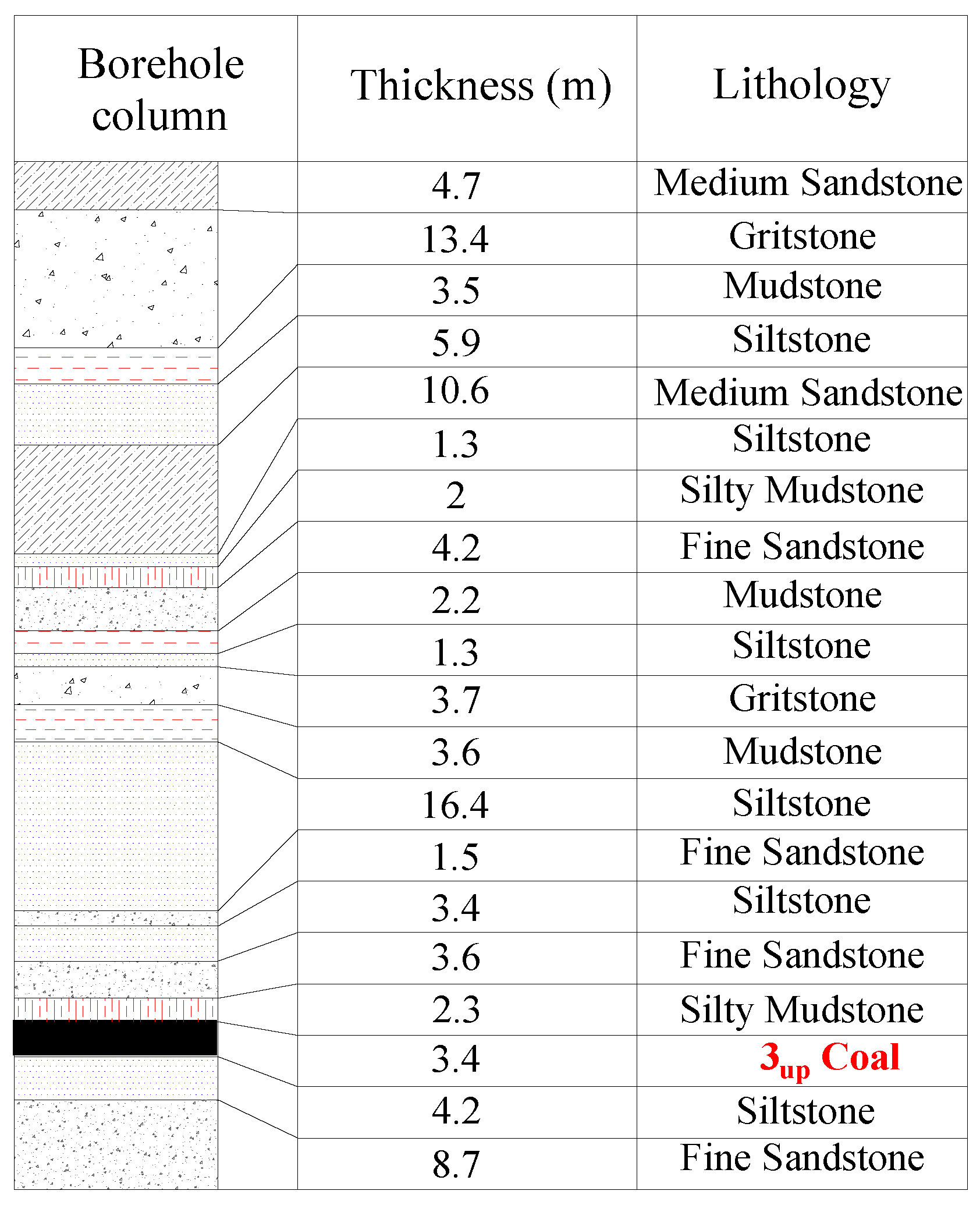
The test roadway was the belt haulageway 1513 with a
f of the 3
up coal seam of about 1–2. The thickness of the coal seam was 3.4 m. The immediate roof was silty mudstone with a thickness of 2.3 m. The main roof was fine sandstone with a thickness of 3.6 m. The concrete occurrence of the roof and floor strata is shown in
Figure 2.
3. Mechanism of Overburden Fracturing and Weighting
3.1. Fracturing Mechanism of Key Strata
3.1.1. Key Strata Identification
According to the key stratum theory, there are one to several thick and hard layers in the overburden strata above the immediate roof, which play a major controlling role in the activities of overburden strata in the stope. The strata that control a component or all of the activities of the overburden in the stope are called key strata. In the process of key strata deformation, the overlying strata controlled by the key strata deform synchronously, while the underlying strata are not coordinated with the deformation. The loading of key strata therefore no longer needs to be borne by the underlying strata assuming that the first key stratum controls n layers, and the (n + 1)
th stratum will be satisfied by Equations (1) and (2) if becoming the second key stratum.
According to the principle of Equation (1), the position of the hard rock layers that may become key strata is assessed from bottom to top, layer-by-layer, until the position of the top layer is determined. Assuming there are K hard rock strata in the overlying stratum satisfying this condition, the determined hard rock strata must also satisfy the strength condition of the key stratum, that is the broken length of the lower hard rock stratum is less than that of the upper hard rock stratum:
According to the occurrence of strata shown in
Figure 2, the position of hard strata that may become key stratum above the first key strata was determined by Equation (1), and all key strata were then determined by Equation (3). The calculation results are shown in
Table 1. There are four key strata in the overlying strata.
3.1.2. Key Strata Fracturing Law
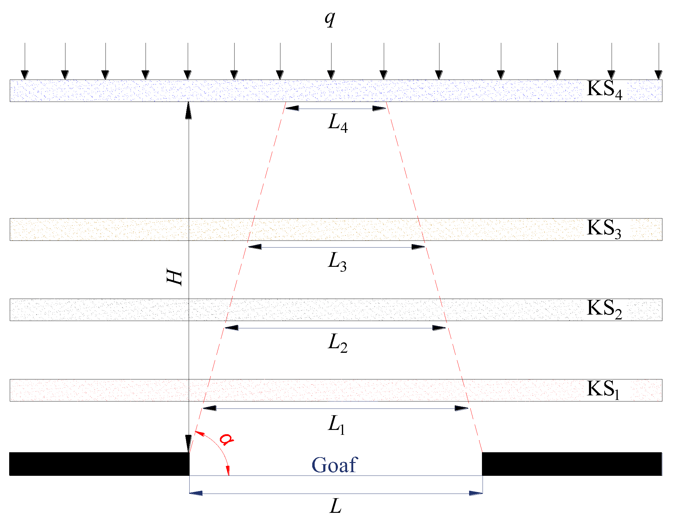
According to the calculation results, there are four key layers above the working face. As shown in
Figure 3, the key layers above the working face are KS
1, KS
2, KS
3, and KS
4 from bottom to top, corresponding to spans of
L1,
L2,
L3, and
L4, respectively.
When the overburden strata above the goaf break and collapse after a coal seam is exhausted, the caving angle α and span of the strata gradually decrease from bottom to top. The rock strata without fracture failure are regarded as clamped beams. The elastic equation is established according to Griffith’s strength theory, and the limit span
Lj of the beam is obtained by Equation (4). From the geometric relationship, the span, caving angle, and vertical height of the KS
n to the working face of the coal seam satisfy the following:
If the span
Ls of a key stratum is larger than its limit span
Lj, the key stratum will break, the overburden combination will break accordingly, and the breaking form will proceed according to
α of the strata. Equation (5) shows that a higher key stratum is associated with a smaller span and a lesser likelihood of collapse. If the stope width is smaller, the span of the corresponding key stratum will also be smaller and the less likely it is to collapse. Therefore, in the high horizon of overlying strata above a narrow goaf, there may be complete key strata that do not collapse. Similarly, the key overlying strata may all break if the stope width is large. According to the occurrence of strata in the working face, α of overlying strata is 70°. The span of overlying key strata is calculated by Equation (5) when the working faces of 1512 and 1511 are exhausted and compared with the limit span of each key stratum. The calculation results are shown in
Table 2.
The span of KS1 above the goaf 1512 (48.3 m) has reached its span limit (43.2 m), whereas the span of KS2 (42.1 m) has not reached its limit (112.7 m). Therefore, after the working face 1512 is exhausted, the caving of overlying strata ceases beneath KS2. Because of its large width, when the working face 1511 is exhausted and becomes a goaf, the spans of the four key strata are larger than their span limits, and all four key strata in the overburden rock break. The overburden pressure in the goaf is then transferred to the small pillars between the two goafs, resulting in the instability and loose destruction of the pillars, which induces further roof subsidence or secondary breakage.
3.2. Pressure Bearing Mechanism of the Coal Pillar
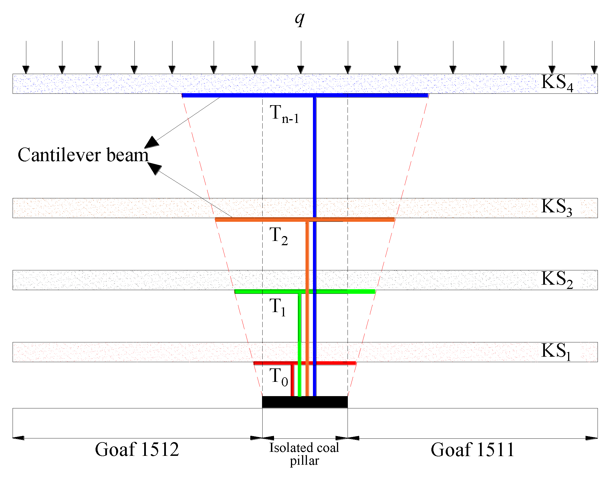
After coal seam mining, the overburden strata of the goaf are broken and cave from bottom to top with caving angle α. At this time, a cantilever beam forms under a key stratum after the strata on the side of coal pillar above the goaf break. The cantilever length is related to the key strata horizon and increases gradually with strata height [
22]. The weight of the overlying strata between two adjacent key strata is borne by the lower key stratum. After certain key strata are broken, the entire weight of the bearing strata is borne by the roadway coal pillar. A cantilever beam forms over the isolated coal pillars with a goaf on both sides by the collapse of the overburden rock at caving angle α. At this time, the pillar bears the weight of the strata below the cantilever beam. According to this definition, the overburden rock under the cantilever beam is defined as the strata in the “T” type area. At this time, the pillar bears the load of the “T” structure, as shown in
Figure 4.
The coal pillar bears the load of the “T0” structure prior to KS1 breakage. After KS1 breaks, the rock caves downward and stops below KS2. The coal pillar bears the load of the “T1” structure, that is the “T” structure under key strata that remains unbroken.
Larger goaf widths are associated with higher breakage horizons of key strata, increased strata of “T” type area, and increased pressure borne by the coal pillar. There are few rock strata in the “T” type area above the chain pillar of a narrow goaf because the lateral abutment pressure above the pillar formed by the “T” type structure is small and the pillar stability is relatively good. On the contrary, increasing goaf width is associated with higher pressure of isolated island pillars, which may cause pillar instability and collapse.
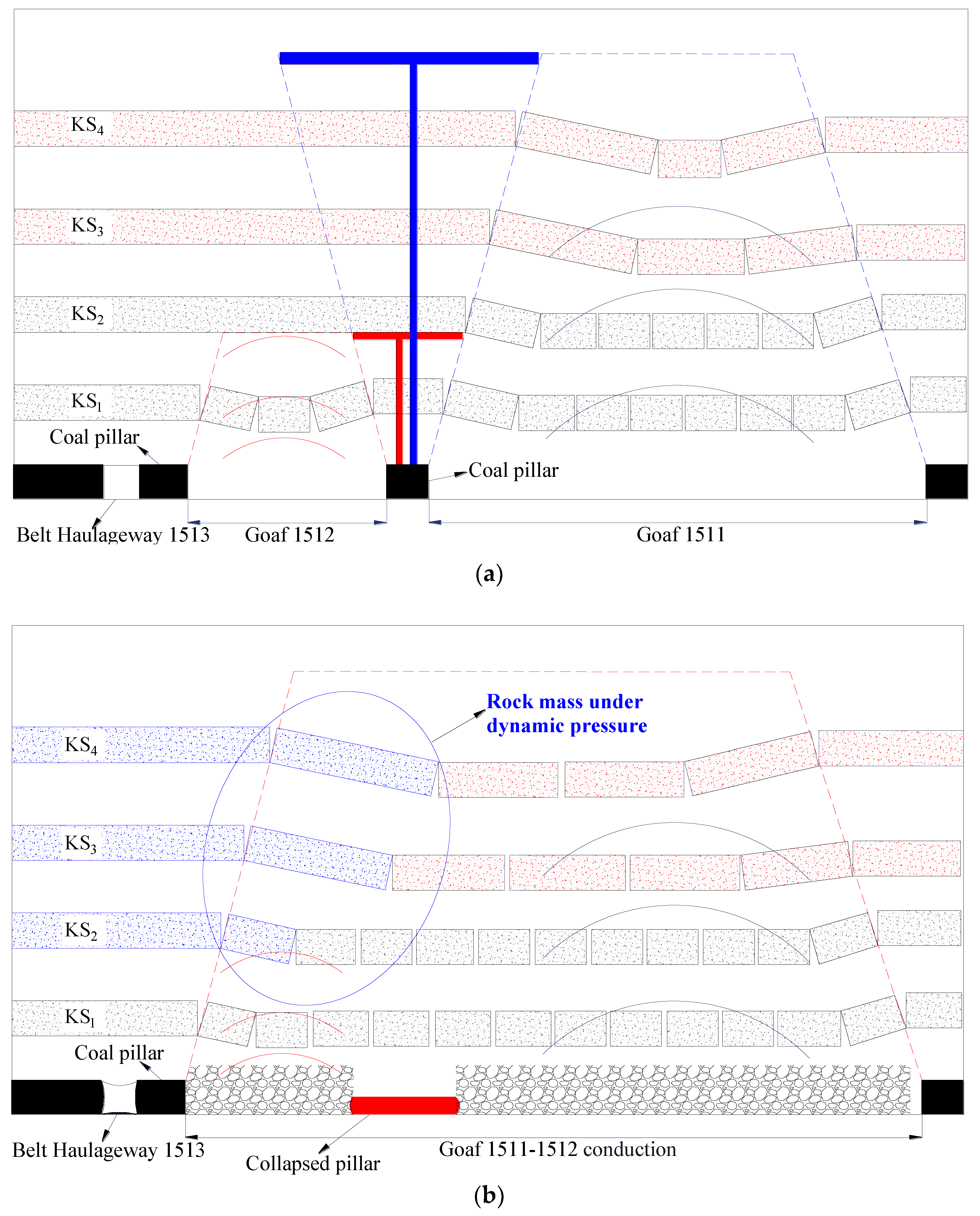
3.3. Mechanism of Strata Fracturing and Weighting of Adjacent Wide and Narrow Working Faces
Mining of the working faces of 1512 and 1511 inevitably isolates the pillar between the two goafs (
Figure 5). After formation of the goaf 1511, the isolated pillar collapses and destabilizes owing to the increased pillar pressure, which fractures the high overlying strata in the goaf 1511 and affects the belt haulageway 1513, resulting in severe roadway deformation.
As shown in
Figure 5, when the working face 1512 is exhausted, only the KS
1 and overlying strata it bore break owing to the narrow width (50 m) of the 1512 goaf. The weight of the overburden strata is then borne by the unbroken key strata and, the chain pillar only bears the load of the low “T” type structure below the key strata. At this time, there are fewer strata in the “T” type area, the pressure borne by the chain pillar is relatively small, and the integrity of the pillar remains acceptable.
When the working face 1511 is exhausted, a 200 m wide goaf forms. The overlying strata collapse upward, layer-by-layer, with a caving angle α, and all key strata are broken. At this time, the small pillars between the two working faces bear the load of the high “T” type structure. With increasing strata in the “T” type area, the pressure of the pillars gradually increases.
When the coal pillar pressure increases, the coal pillar eventually collapses, and a larger goaf forms by the 1512 and 1511 working faces. At this time, the span of the key unbroken strata above the goaf 1512 instantaneously increases, resulting in fracturing, which makes the fracture horizon continue to expand upward. The fracture of overlying strata forms dynamic pressure rock blocks, which disturb the dynamic pressure of the belt haulageway 1513, resulting in severe deformation of the roadway.
3.4. Field Verification of Overlying Key Strata Fracturing
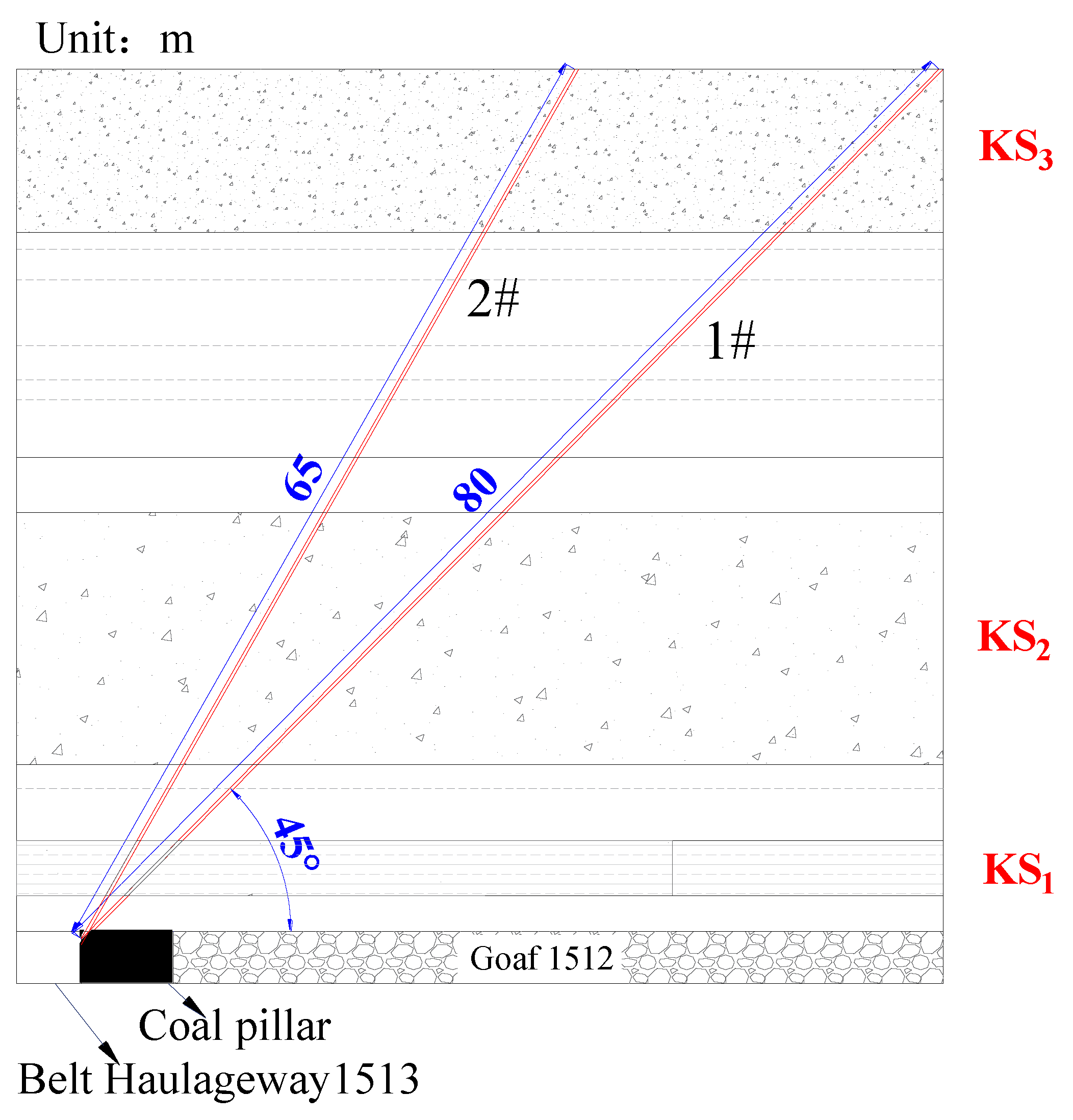
To verify that the caving horizon of key strata above the goaf 1512 are related to mining in the working face 1513, two groups of boreholes (
Figure 6) were constructed in the belt haulageway 1513 before mining of the working face 1513. The angles of the two boreholes groups were 45° and 60° with lengths of 55 and 45 m, respectively (reaching the height of KS
3). A comparison of the peeping results is shown in
Figure 7 before and after mining of the working face 1513.
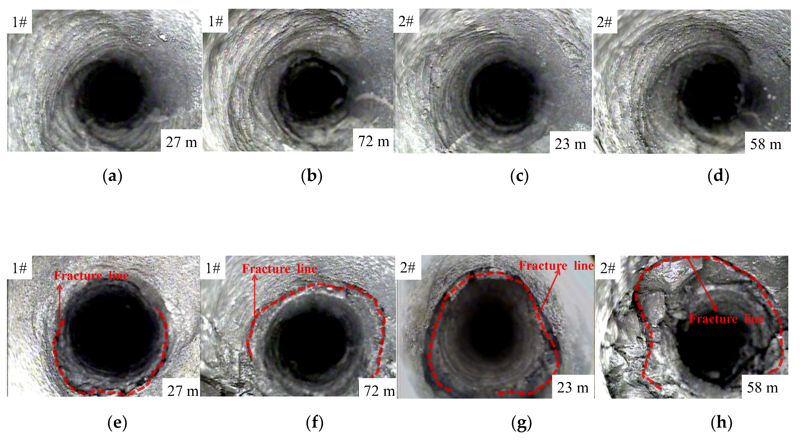
Figure 7 shows that before mining of the working face 1511, the KS
2 and KS
3 strata of the first and second group boreholes were relatively complete, and no fracture lines or fissures were observed. After exhaustion of the working face 1511, the first and second group boreholes show that KS
2 and KS
3 strata had different degrees of rock fracture line and crack development. As a result and owing to the small width of the working face, caving of the overburden strata above the goaf ceases below KS
2 when the working face 1512 is exhausted, and KS
2 and KS
3 are relatively complete without fracture. After mining of the working face 1513, the caving horizon of the overlying strata above the goaf increases because of the large working face width, which leads to an increase of pressure of the isolated pillar between the goafs of 1512 and 1513. The pillar eventually becomes unstable and collapses, resulting in fracture of unbroken KS
2 and KS
3 above the goaf 1512 to form dynamic pressure rock blocks, which cause stress fluctuation in the belt haulageway 1513.
4. Disturbance Law of the Goaf-Side Roadway Induced by Overburden Fracturing and Weighting
4.1. Setting up the Numerical Model
We establish a numerical model (
Figure 8) using finite difference software FLAC
3D according to the engineering geological and mining conditions of the Xinyi coal mine. The thickness of the coal seam was 3.4 m; the width of the working face 1512 was 50 m; the width of the working face 1511 was 200 m; the width of the coal pillar between the working faces of 1512 and 1511 was 5 m; and the width of the coal pillar along the goaf was 6 m. The upper boundary load of the model was calculated according to the actual mining depth of 500 m, and the upper end of the model was free to apply a vertical load of 12.5 MPa. The bottom boundary of the model was fixed vertically, and the left and right boundaries were fixed horizontally without displacement. The model adopted the Mohr-Coulomb yield criterion. The physical parameters of rock strata were taken from the same coal field in the Xinyi coal mine [
23,
24].
The mining sequence was as follows: (1) mining of the working face 1512; (2) excavation of the belt haulageway 1513 along the goaf 1512; and (3) mining of the working face 1511. The influence of the working face 1511 mining on the stress and displacement disturbance of the belt haulageway 1513 was calculated and analyzed.
4.2. Stress Disturbance Characteristics
After mining of the working face 1511, the unbroken key strata above the working face 1512 broke, rotated, and subsided to form dynamic pressure rock blocks. In this process, the dynamic pressure rock blocks produced vertical and horizontal stresses, which affected the stress state of the rock surrounding the belt haulageway 1513 and caused a redistribution of the stress. To analyze the specific stress influence law, two survey lines of horizontal and vertical stresses were arranged at the 2 m level of the coal seam roof built using the FLAC
3D numerical model. The absolute values of the data measured by the survey line are shown in
Figure 9 and
Figure 10. In
Figure 9, positive values represent horizontal stress to the left. In
Figure 10, positive values represent vertical stress downward.
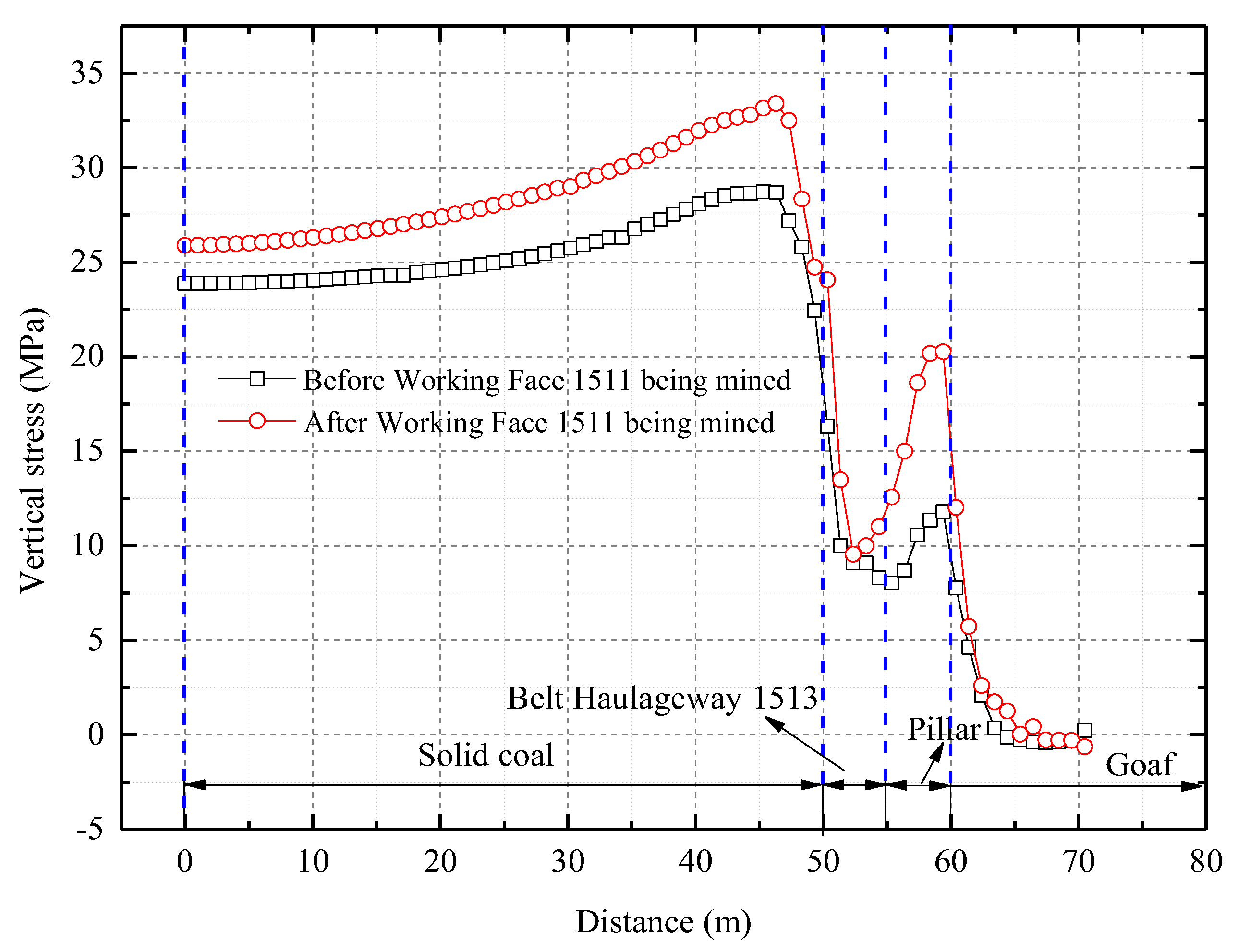
Figure 9 shows that the peak vertical stress increased by 61.5%, from 13 to 21 MPa, above the coal pillar along the goaf after mining of the working face 1511 with the peak value close to the goaf side. The amplitude increase of the vertical stress above the roadway gradually decreased as it approached the coal pillar side. The peak lateral vertical stress of the roadway solid on the coal side increased from 28 to 32 MPa.
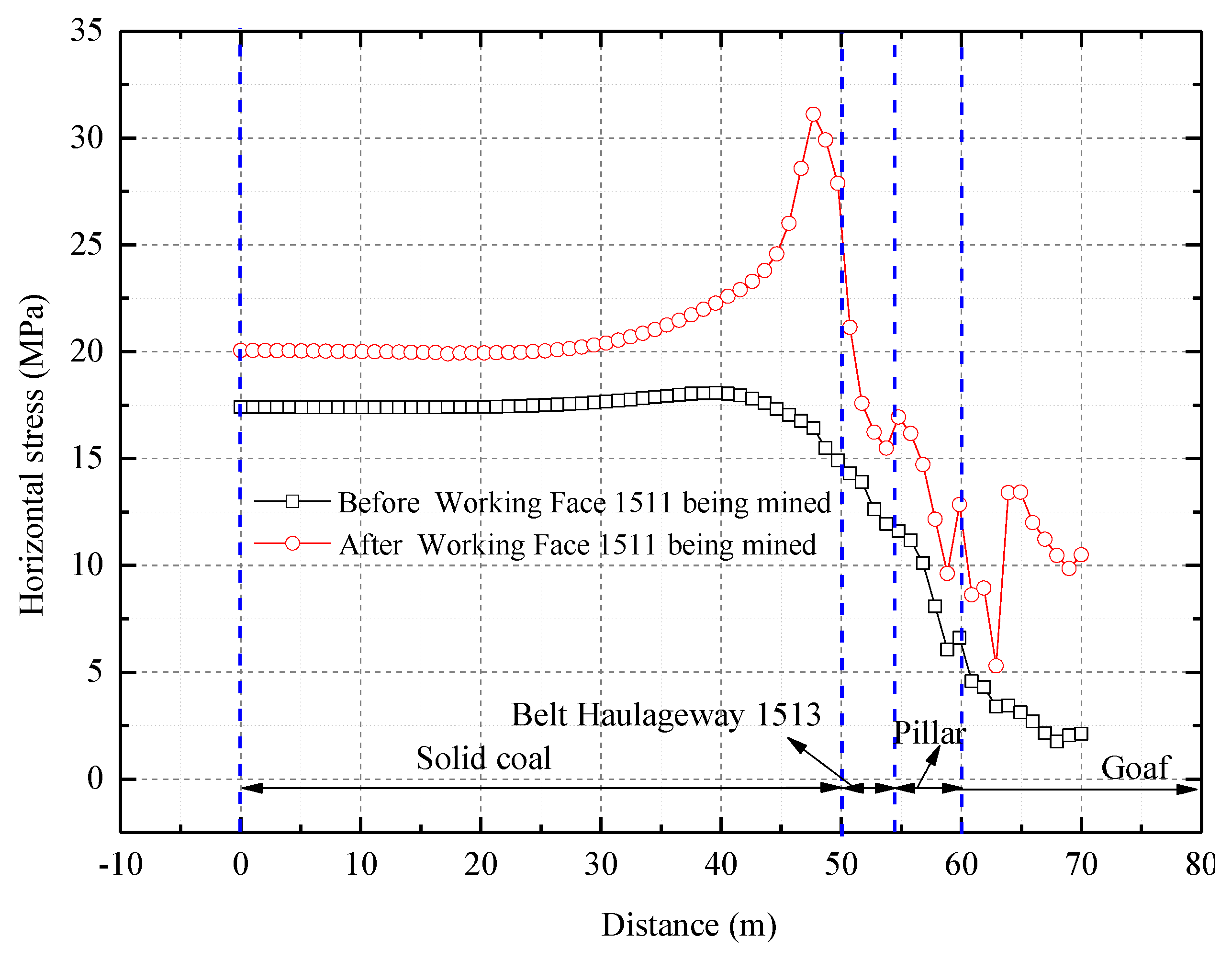
Figure 10 shows that the horizontal stress disturbance of the rock surrounding the belt haulageway 1513 was more apparent than the vertical stress. The peak lateral horizontal stress of the solid coal side of the roadway increased by 85.5% from 16.8 to 31.1 MPa. The distance between the peak stress point and the roadway’s solid coal side decreased dramatically from 9 to 3 m. The horizontal stress above the belt haulageway 1513 and pillar increased, and the amplitude of the horizontal stress gradually decreased along the right side owing to the gradual weakening of the dynamic pressure rock blocks.
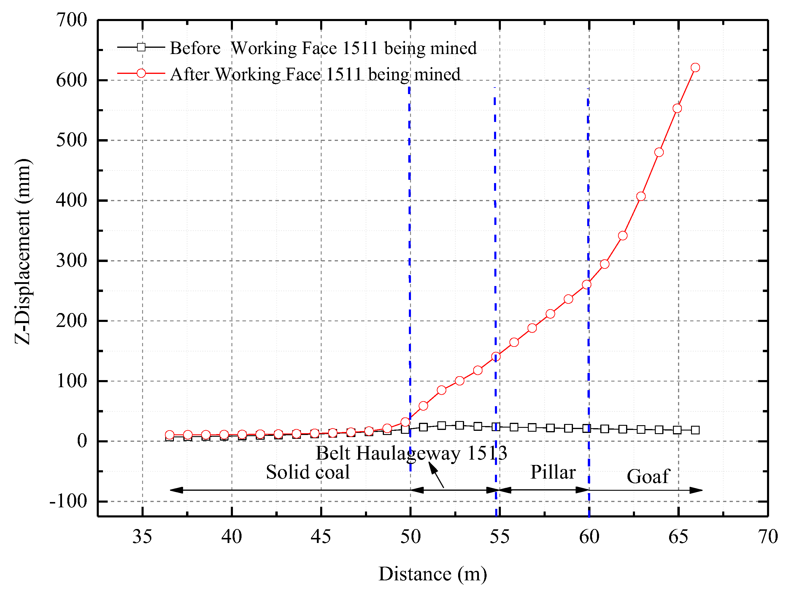
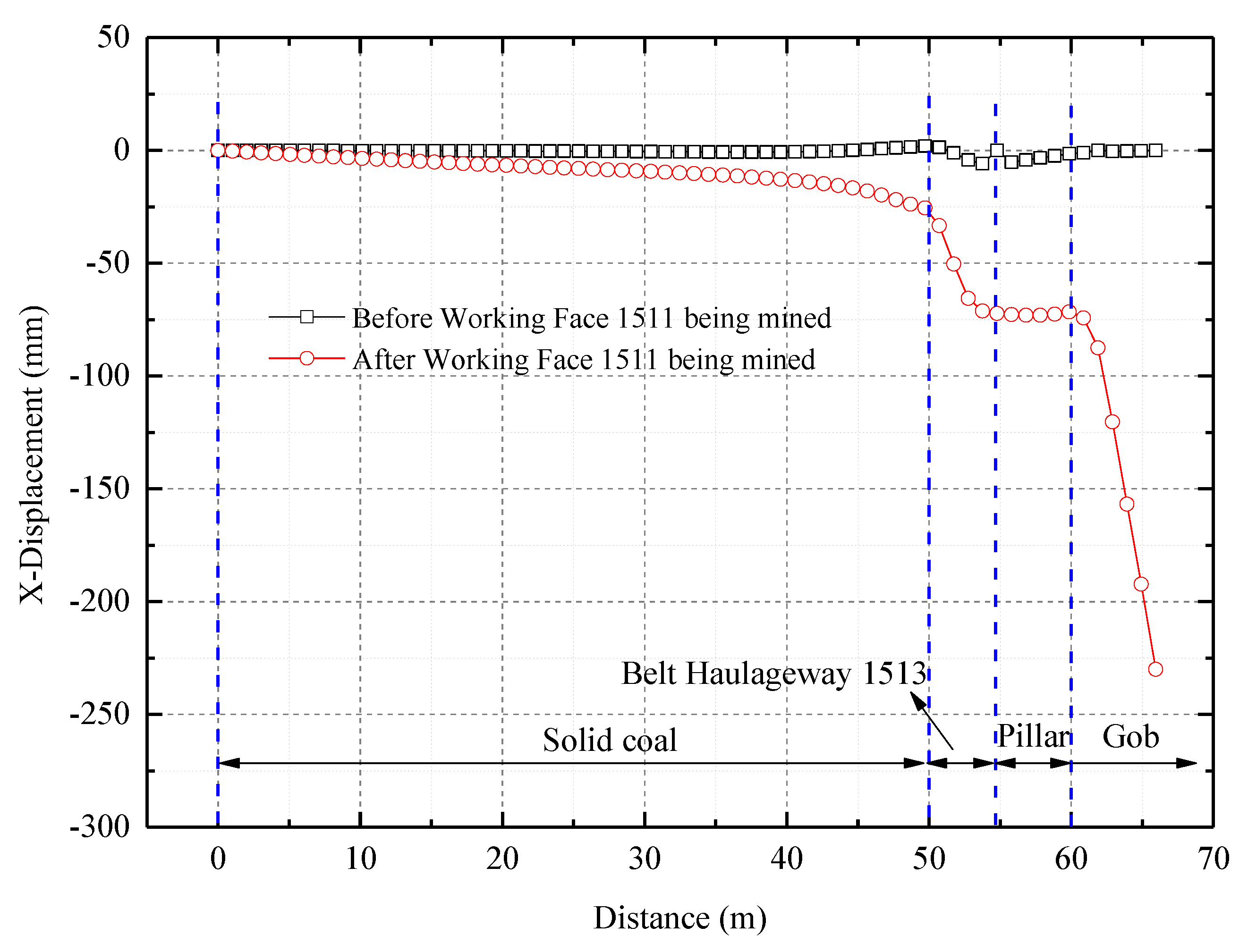
4.3. Deformation Characteristics
Vertical and horizontal deformation of the roadway roof and coal pillar occurred after mining of the working face 1511 owing to vertical and horizontal stress during the rotary subsidence of dynamic pressure rock blocks. To understand the concrete influence law, two survey lines of vertical and horizontal displacement were arranged in the numerical model at the 2 m level of the coal seam roof. The absolute values of the data measured by the vertical displacement survey line are shown in
Figure 11 where positive displacement values represent downward displacement. The true data of the horizontal displacement survey line are shown in
Figure 12 where positive displacement values represent horizontal displacement to the left.
Prior to mining of the working face 1511, the vertical displacement of the 2 m coal seam roof horizon was essentially zero, and only a small amount of displacement (5 mm) occurred above the roadway roof and coal pillar with good integrity. Extensive asymmetric vertical deformation occurred above the roadway roof and coal pillar after mining of the working face 1511 with vertical deformation increasing from left to right, which was consistent with the viewpoint of the inclination direction of the key block of the lateral roof in the goaf. The maximum vertical displacement point above the roadway was located on the side of the coal pillar with a displacement of 145 mm. The maximum vertical displacement point above the pillar was located on the side of the goaf 1512 with a displacement of 260 mm. The vertical stress caused by rotary subsidence of the dynamic pressure rock blocks significantly disturbed the vertical deformation of the roadway roof and coal pillar.
Figure 12 shows that after mining of the working face 1511, horizontal deformation above the roadway and coal pillar was minimal, which was mainly owed to the fact that horizontal roof displacement was more substantial than vertical displacement under the rotational moment of the dynamic pressure rock blocks. Because of the integral displacement of the dynamic pressure rock blocks, the horizontal displacement above the coal pillar was relatively stable with a displacement of 75 mm. The roadway roof was at the junction of the dynamic pressure key blocks A and B, and asymmetric horizontal displacement occurred. The maximum horizontal displacement near the coal pillar side was 70 mm, and the minimum horizontal displacement near the solid coal side was 25 mm. The amplitude of the horizontal displacement gradually decreased with the depth of the solid coal side of the roadway.
5. Stability Control Technology of Goaf-Side Roadway and Engineering Practice
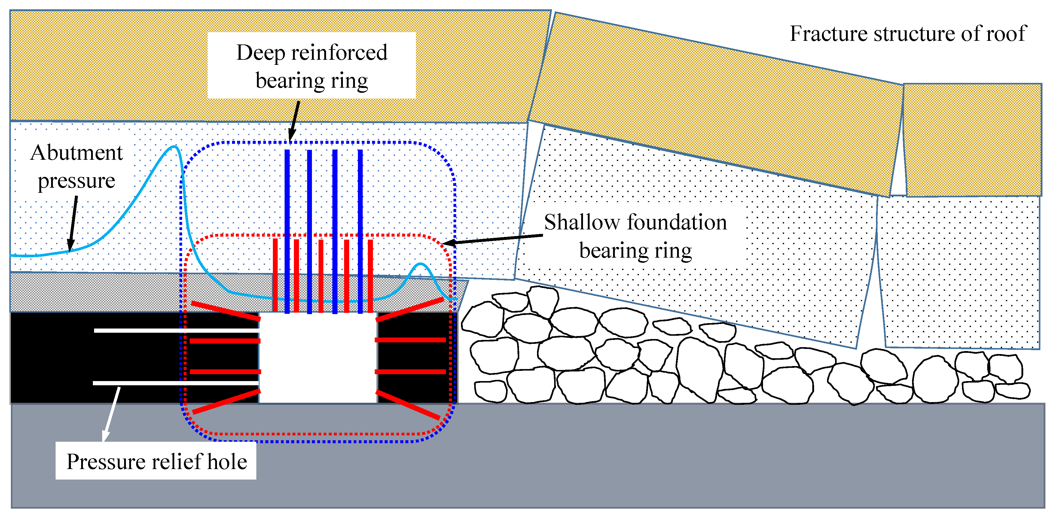
5.1. Stability Control Technology of Integrated Pressure Relief and Anchorage for the Goaf-Side Roadway
Mining of the working face 1511 caused substantial disturbance and deformation of the belt haulageway 1513. Through the construction of pressure relief boreholes [
25,
26] on the solid coal side of the roadway, the stress can be reduced and transferred to a deeper section. By releasing its internal energy, the stress concentration was eliminated, and the stress fluctuation caused by mining of the working face 1511 on the belt haulageway 1513 was alleviated, which optimized the stress environment of the “small structure” of the roadway. Through the construction of a roof equidistant and double load bearing ring on the basis of improving the stress environment by pressure relief of the coal side, the double load bearing ring (
Figure 13) would be constructed on the roadway roof. On the basis of effectively controlling the development of a large number of secondary cracks at the lateral disturbance area of the goaf, the anti-disturbance ability of a roof anchorage system would effectively improve the coping capacity of fluctuations of strong mining stress caused by mining of the working face 1511 and ensure stability of the roadway roof support system [
24].
5.2. Support Scheme Design
Considering that mining of the working face 1511 will inevitably cause stress fluctuations in the belt haulageway 1513, supporting technology in the excavation stage is particularly important. According to the engineering geological conditions and previous theoretical and technical analyses, the supporting parameters of belt haulageway 1513 were designed as follows.
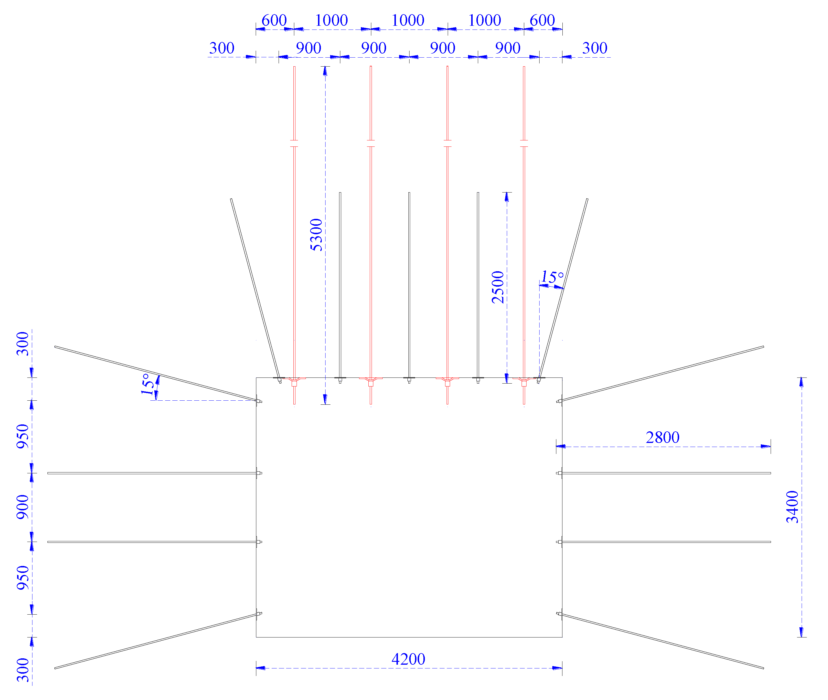
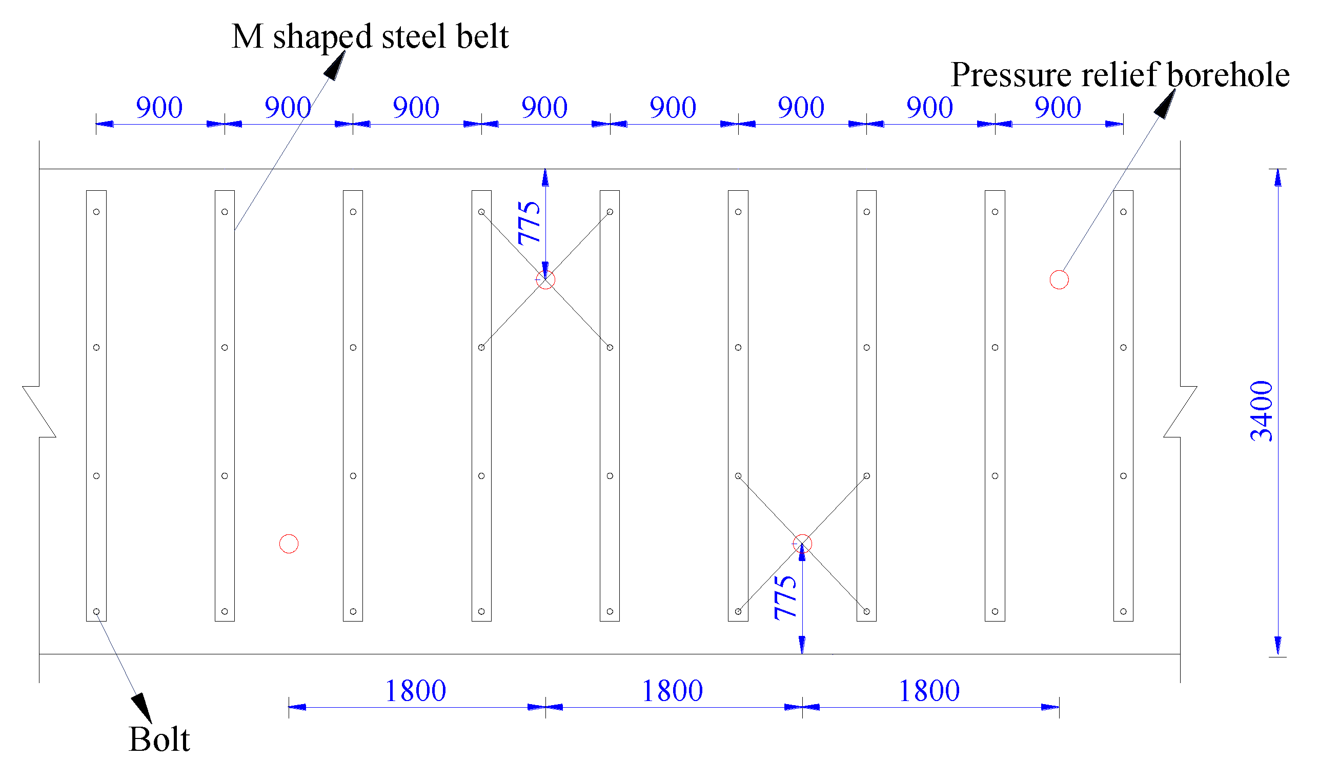
The cross-section of the belt haulageway 1513 was rectangular with dimensions of 4.2 m in width and 3.4 m in height. As shown in
Figure 14, the roadway roof was supported by bolts and cables with equal row spacing. The roof was supported by five Φ22 × 2500 mm high strength pre-tightening bolts, four Φ21.8 × 6100 mm steel stranded high strength pre-tightening anchor cables, and M shaped steel belts and bar-mat reinforcement for surface protection. The inter-row spacing of the bolts and anchor cables was 900 × 2000 mm and 1000 × 2000 mm, respectively. The pretension of the roof bolts and anchor cables was 60 and 120 kN, respectively. The two ribs were supported by four Φ20 × 2800 mm bolts with wire meshes and M shaped steel belts for surface protection with a rib bolt pretension of 40 kN. The pressure relief boreholes were constructed every two rows on the solid coal side to guide the mining stress to be transferred to a deep section to create a low stress environment for the roadway. The boreholes were located in the center of the four bolts to avoid disturbing the anchoring stress. The diameter, depth, and row spacing of the boreholes were 125 mm, 10 m, and 1.8 m, respectively. A cross-section of the bolt and cable support and specific layout of pressure relief boreholes for the solid coal side are shown in
Figure 15.
5.3. Supporting Effects Analysis
To grasp the deformation law of the belt haulageway 1513 during excavation and mining of the working face 1511 and to verify the influence of mining the latter on the former and the feasibility of integrated control technology of pressure relief and anchorage, a monitoring station was arranged at the middle of the roadway, and cross-sectional measurement methods were adopted to monitor the deformation data of roof subsidence and convergence of the two sides of the roadway (
Figure 16).
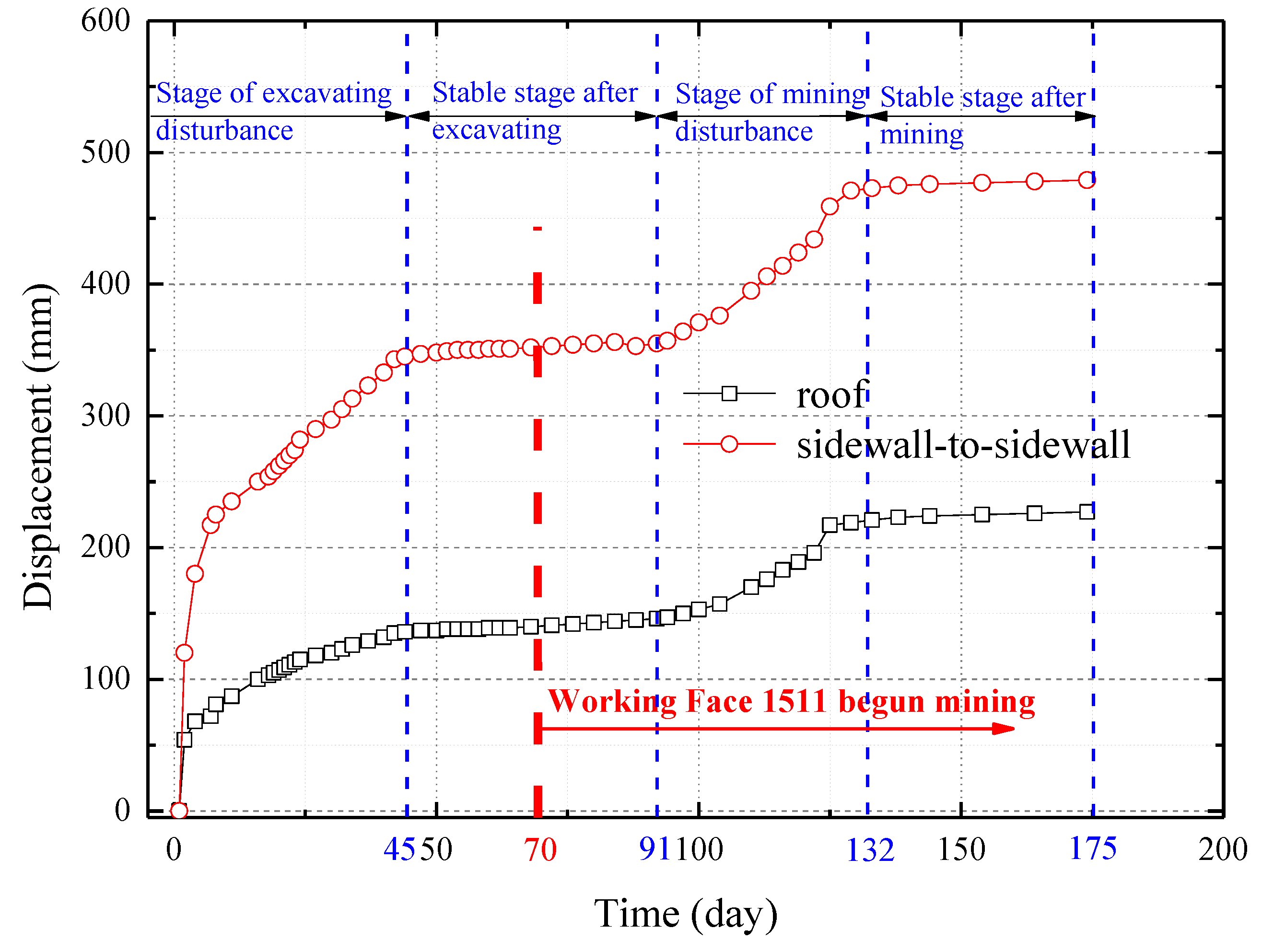
As shown in
Figure 16, the stress redistribution of the surrounding rock in the initial stage of roadway excavation under the influence of dynamic pressure caused deformation of the roadway surrounding rock, and the displacement of the roof and two sides increased continuously. After 45 days, the deformation reached a stable level. At this time, roof subsidence was stable at 130 mm, and displacement of the two sides stabilized at 350 mm during the excavation disturbance stage. From the 45
th to the 70
th day, deformation did not increase further during the stable stage after excavation.
On the 70th day, the belt haulageway 1513 was fully excavated and the working face 1511 began to be mined. The mining influence was small from the 70th to the 91st day owing to the distance between the measuring station and the working face 1511, and deformation remained stable and did not increase. After the 91st day, a larger impact on the roadway occurred as the working face 1511 continued to move forward with decreasing distance from the measuring station. Deformation began to increase from the 91st to 132nd day during the mining disturbance stage.
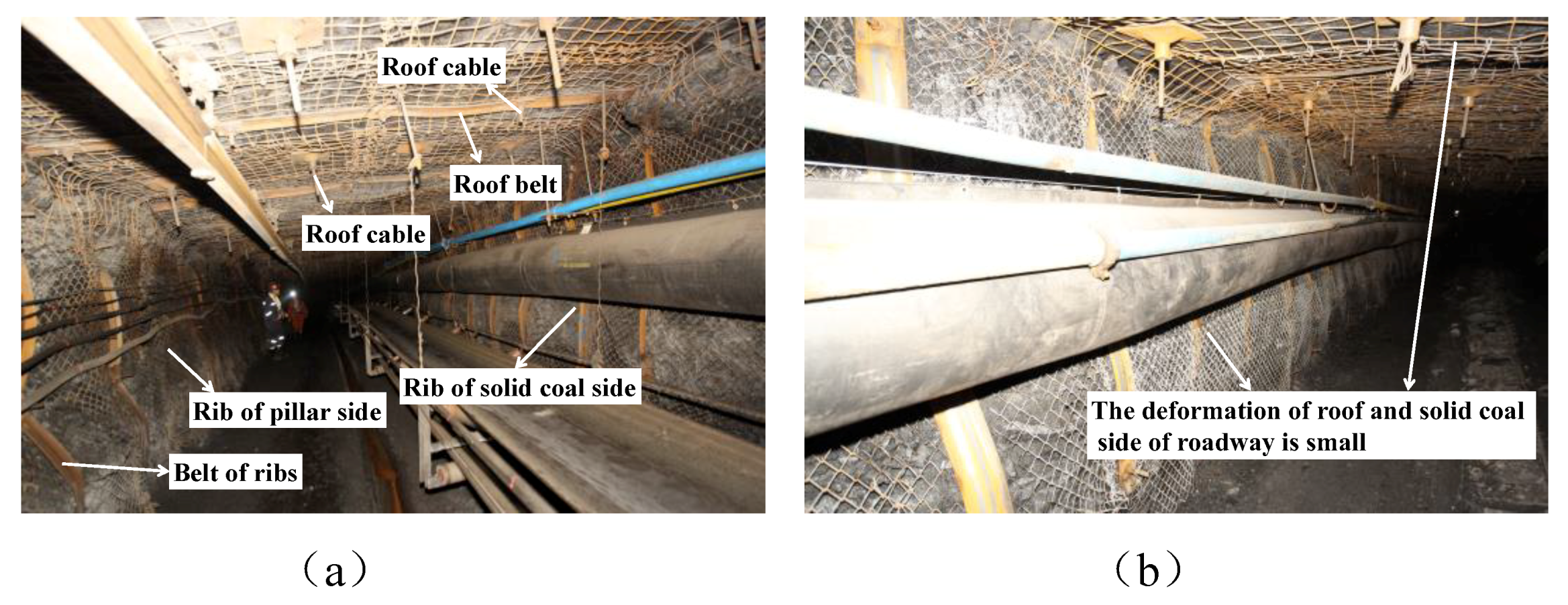
The final deformation reached a stable level with the working face 1511 away from the measuring station. At this time, the roof subsidence was stable at 220 mm, and displacement of the two sides was stable at 470 mm. The period from the 132
nd to 175
th day was the stable stage after mining. Generally speaking, deformation of the belt haulageway 1513 was small, and the surrounding rock was effectively controlled with good supporting effects (
Figure 17).
6. Conclusions
In this study, theoretical analysis, numerical simulation, and engineering practice were carried out to reveal the mechanism of overburden key strata fracture, stress distribution, and deformation characteristics of the surrounding rock of belt haulageway 1513 due to mining disturbance of working face 1511. From these studies, the following conclusions were drawn:
(1) The position of key strata in the overburden strata of the mining face was calculated and analyzed according to key strata theory, and four key strata were identified. The caving horizon of the overlying key strata was calculated when the working faces of 1512 and 1511 were fully mined. When the working face 1512 was exhausted, the collapse of overlying strata ceased below KS2. At the end of mining the working face 1511, all four key strata collapsed.
(2) The bearing mechanism of the coal pillar was determined theoretically. The weight of the overlying strata between two adjacent key strata was borne by the lower key strata. After a certain key stratum was broken, the entire weight of the bearing strata was borne by the coal pillar. Above the isolated pillar in the goaf on both sides, the pillar bore the weight of the rock strata (“T” type area) below the cantilever beam. Larger goaf width was associated with a higher horizon of broken key strata. The pressure of the coal pillar increased with increasing strata in the “T” type area.
(3) The mechanism of overburden breaking and weighting in alternate mining of adjacent wide and narrow working faces was determined. When the working face 1512 was fully mined, caving of the overlying strata ceased below KS2. When the working face 1511 was fully mined, the four key strata broke and the coal pillar pressure gradually increased, resulting in the final collapse of the coal pillar, connection of the goafs 1512-1511, and the formation of a larger goaf. At this time, the unbroken key strata above the goaf 1512 broke to form dynamic pressure rock blocks, causing a dynamic pressure disturbance on the belt haulageway 1513 and resulting in severe deformation of the roadway. Secondary breakage of the unbroken strata above the goaf 1512 was related to mining of the working face 1511 through on-site borehole peeping.
(4) The disturbance law of mining in the working face 1511 on the belt haulageway 1513 was analyzed using FLAC3D numerical simulations. After the working face 1511 was fully mined, the horizontal stress disturbance on the belt haulageway 1513 was more apparent compared with vertical stress, the peak lateral horizontal stress of the roadway on the solid coal side increased substantially, and the peak point was closer to the coal rib. At the same time, the rotary subsidence of dynamic pressure rock blocks caused large deformation above the roadway and pillar. Because of the integral displacement of the dynamic pressure rock blocks, the vertical displacement disturbance on the belt haulageway 1513 was clearer compared with the horizontal displacement, and the vertical deformation gradually increased from left to right, which was consistent with the viewpoint of an inclination direction of the key block of the lateral roof in the goaf.
(5) Aiming at the disturbance law of mining of the working face 1511 on the belt haulageway 1513, this study proposed stability control technology of integrated pressure relief and anchorage, and industrial tests were performed. According to monitoring of the surface displacement of the roadway in the field, the displacement law presented four stages: excavating disturbance, stable stage after excavating, mining disturbance stage, and stable stage after mining. The control effect was good, verifying the influence of mining of the working face 1511 on the belt haulageway 1513 and the feasibility of an integrated control technology of pressure relief and anchorage. A highly efficient and sustainable roadway surrounding rock control technology was therefore possible under such mining conditions of the goaf-side roadway.
It is of note that the research of side roof pre-cutting technology and pre-cutting time in the gob side of the roadway under the influence of adjacent working face mining will be further worthy of investigating in future studies.

 ,
, 


