1. Introduction
Two of the major outputs from the Fifth Assessment Report of the Intergovernmental Panel on Climate Change (IPCC) are that the consequences of uncontrolled climate change for humans and natural ecosystems are evident and that the anthropogenic impact on the climate system has been increasing in recent years [
1,
2]. Limiting climate change will require a substantial and stable reduction of greenhouse gas (GHG) emissions, and strong effort is required, especially for the research and development of innovative technologies and strategies. Since the Industrial Revolution, humans have increasingly altered the global carbon cycle, and the rising concentration of atmospheric carbon dioxide (CO
2) has become a growing concern [
3,
4]. Mitigation (
i.e., the human intervention to reduce the sources or enhance the sinks of greenhouse gases) together with the adaptation to climate change can effectively contribute to the objective of reducing the GHG concentration [
5,
6,
7,
8].
The energy supply sector (energy extraction, conversion, storage, transmission and distribution processes) [
9] represents the largest contribution to global GHG emissions, and it is characterized by an increasing demand for energy services and a growing share of coal in the global fuel mix. More than 75% of the 10-Gt increase in annual GHG emissions between 2000 and 2010 was produced by the energy supply (47%) and industry (30%) sectors [
10]. There is a multitude of options to reduce GHG emissions from this sector, including: (i) energy efficiency improvements and fugitive emission reductions in fuel extraction, as well as in energy conversion, transmission and distribution systems; (ii) fossil fuel switching; and (iii) low GHG energy supply technologies, such as renewable energy, nuclear power and carbon capture and sequestration (CCS). The energy production from renewable energy sources (RES), such as solar, wind, biomass, geothermal,
etc., represents a key strategy to fulfill the present energy need in a sustainable way [
11,
12,
13] and to diversify energy supply, reducing the dependence on oil and gas and improving security [
14].
The European Commission is promoting innovative initiatives to redesign cities, through the use of new technologies to increase the energy efficiency of buildings [
15], energy networks and to develop new strategies for sustainable urban transport systems [
16,
17]. Thanks to these actions, cities are foreseen to become smart cities [
18,
19], a collection of interconnected networks (transportation, power grid, district heating [
20,
21], buildings [
22,
23], public lighting, water, waste, social life,
etc.).
The current national electricity grids are in general unable to address the major issues related to an intensive use of non-programmable and distributed energy generation plants (
i.e., renewables). This scenario requires a rapid development of a novel and revolutionary paradigm, the so-called smart grid [
24], that can reduce energy use and carbon impacts associated with the generation and distribution of electricity.
Life cycle assessments for electricity generation (
i.e., carbon footprint, [
25,
26]) indicate that GHG emissions from RES technologies are, in general, significantly lower than those associated with fossil fuel options [
10]. Among the major RES,
i.e., bioenergy, photovoltaic, concentrating solar power, geothermal energy, hydropower, ocean energy, wind energy and waste-to-energy, the latter has the additional beneficial effect of reducing carbon-based emissions associated with other forms of disposal [
27]. Despite the large availability of studies on the environmental performances of RES plants [
28,
29], there is very little literature about integrated systems exploiting multiple sources of renewable energies, mostly focusing on energy and economic performance [
30,
31,
32] or operating jointly with fossil-fuel energy plants [
33,
34]. Investigating the environmental performance of integrated RES plants can represent a valuable instrument to guide designers and decision makers towards a cleaner and more sustainable energy production paradigm.
The technical potential of RES exceeds the global electricity, heat and global primary energy demand. However, on average, they require large land surfaces with respect to conventional energy sources during their life cycle. Two estimators can be used to define the land use associated with energy production: land transformation and land occupation [
35]. The former is defined as the total surface area that is altered by the entire energy production process. The latter describes the area occupation over time.
In this paper, an innovative solution to reduce the environmental impact arising from energy production in urban areas is presented. Two indicators, carbon footprint (CF) and land use, are evaluated to assess the environmental performance of the system.
Section 2 describes the Multifunctional Environmental Energy Tower (MEET), a stand-alone building designed to maximize the exploitation of renewable energy sources available in place, to overcome problems related to their non-programmability and to be an active node of energy smart grids.
Section 3 describes the methodology used for the carbon footprint and land use analyses, performed over the entire MEET life cycle, in order to evaluate its potentialities in terms of clean energy supply coverage, including waste-to-energy conversion, reduction of GHG emissions and minimization of land use. A prototypal MEET is designed for an urban area within the city of Rome, Italy. Renewable energy plants are sized and integrated according to the characteristics of the implementation site.
Section 4 shows the LCA results, the comparison with current state-of-the-art technologies and the capabilities of the MEET to cover the local energy demand. The novelty of this research is represented by the integration of different renewable energy sources in a location-adaptive approach, as an effective instrument to reduce GHG emissions and land use associated with the energy sector.
2. The Multifunctional Environmental Energy Tower
The Multifunctional Environmental Energy Tower (MEET) is an innovative conceptual energy production plant that is specifically designed to maximize the exploitation of renewable sources available in an urban context, following the principles in the European Union objectives for 2020 [
36].
The conceptual design of the MEET [
37,
38], developed by the Biomass Research Center (CRB) of the Interuniversity Research Center on Pollution and Environment (CIRIAF), University of Perugia, makes it a node of energy production from RES in the city of the future, where energy smart grids are a key asset to foster energy efficiency [
24]. A single stand-alone structure is designed to integrate different renewable energy sources available in place, including the energy conversion of urban organic waste. The result is an intelligent system, possibly equipped with energy storage devices [
39], able to combine together energy demand and supply requirements and to overcome some of the problems related to renewable energy source usage: their non-programmability, land occupation and social acceptance.
The MEET was originally designed to be located in the area south of Rome (Tor di Valle), close to the river Tiber. The site is served by a thermal power station, producing electricity and connected to a district-heating network and a sewage treatment plant. The population of the district is 35,000. The MEET provides thermal energy for the district-heating network and produces electricity to be fed into the grid. The conceptual idea can be easily adapted to and optimized for different scenarios, including renewable energy sources and infrastructures that are locally available. The integrated RE technologies are (i) a photovoltaic (PV) plant, (ii) a geothermal plant and (iii) a digester plant that allows energy recovery from urban organic waste and sewage sludge. Anaerobic digestion [
40,
41] is an attractive solution for converting raw solid organic wastes [
42] into useful products, such as biogas and other energy-rich compounds, which may play a major role in meeting the world’s ever-increasing energy requirements in the future [
43].
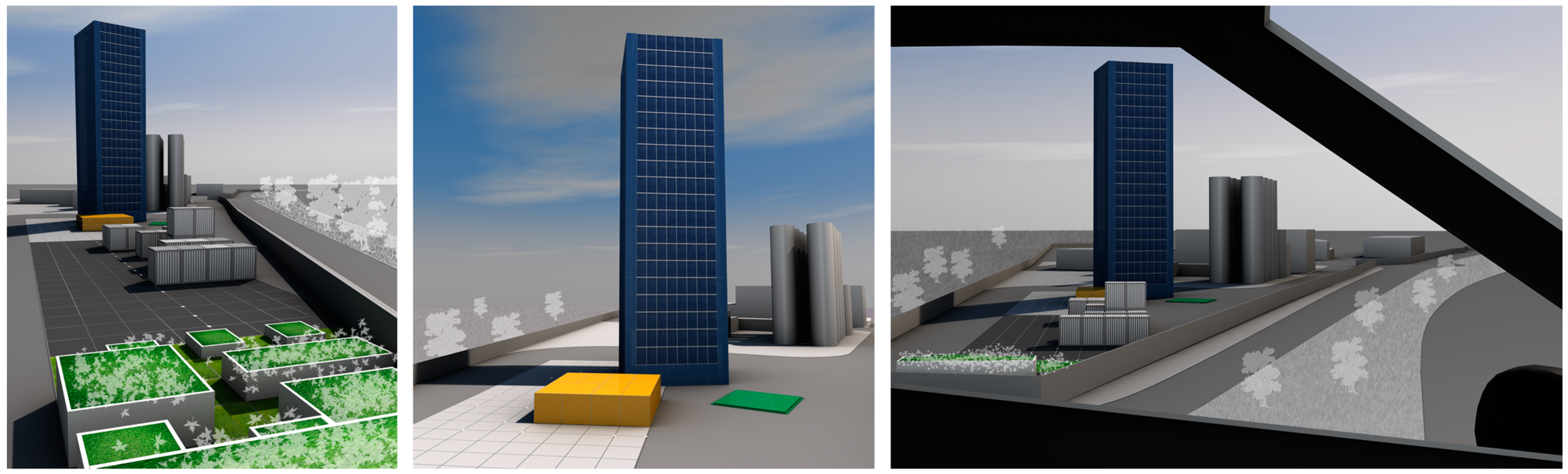
The MEET can also be seen as an icon of environmental sustainability, promoting a new way of producing energy. An appropriate choice of shapes, materials, colors, graphics and lights can be adopted to make the MEET a recognizable symbol of energy efficiency and technological innovation integrated with the surroundings (
Figure 1). The translucent appearance of polycarbonate panels covering the facades, along with high thermal insulation and lightweight properties, allow the observer to ponder the technological heart of the MEET while optimizing its performances [
44].
Figure 1.
Rendering of the tower.
Figure 1.
Rendering of the tower.
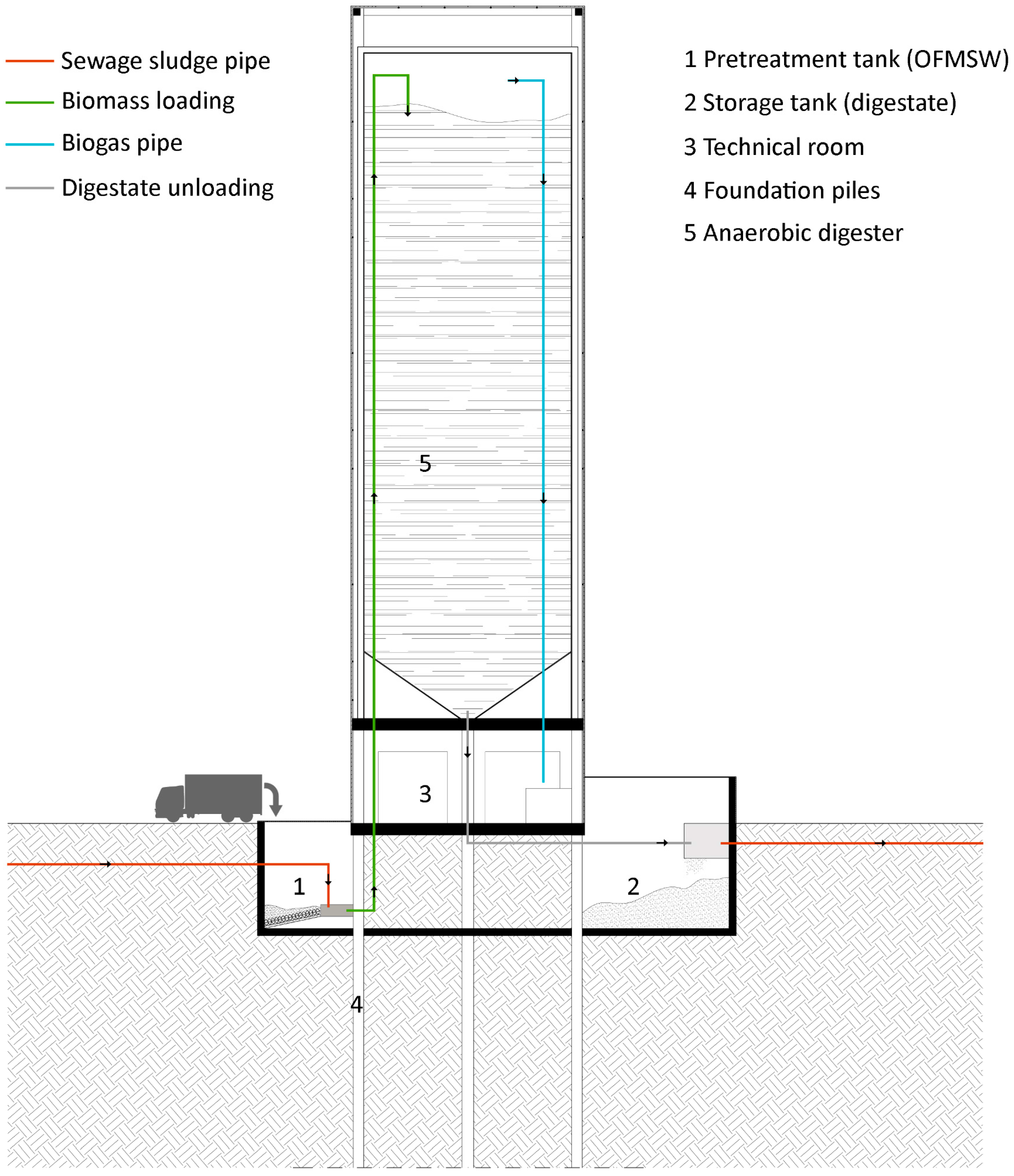
The MEET (
Figure 2) is parallelepiped with a square base (10-m side) and 35 meters high. The ground floor is reserved for a technical room, and an anaerobic digester for the production of biogas is placed above. PV panels cover the sun-exposed surfaces. Geothermal boreholes are integrated into the pilings of the structure. An underground pretreatment tank is used to collect the OFMSW (organic fraction of municipal solid waste), crush and mix it with the sewage sludge coming from the nearby wastewater treatment plant through underground pipes. At the end of the digestion process, the digestate is sent to an underground storage tank in which the separation of the solid part from the liquid takes place.
Figure 2.
Cross-section of the Multifunctional Environmental Energy Tower (MEET).
Figure 2.
Cross-section of the Multifunctional Environmental Energy Tower (MEET).
South, east and west facades (350 m
2 each) and the roof (100 m
2) are covered with PV panels with a nominal peak power of 0.129 kW
ep/m
2. A total energy equal to 128,859 kWh
e/year can be produced (
Table 1). In this case study scenario, vertical facades are not shaded by other buildings. An efficiency reduction of PV production, however, should be considered if the system is designed in different urban contexts.
The biogas plant uses OFMSW collected within the district and sewage sludge generated from the municipal wastewater treatment plant. Thermal and electric energy is produced by a cogeneration unit. The collection of OFMSW guarantees considerable savings in OFMSW transportation and a reduction of natural gas demand for the district heating network. Part of the digested matter is finally returned to the wastewater network, and part is dried and can be used as fertilizer. Dry thermophilic anaerobic digestion, taking place at temperatures between 50 and 60 °C, is characterized by high yields of biogas and low solid retention times [
45,
46]. Co-digestion of sewage sludge is used to improve the biogas yield of the anaerobic digestion of solid organic wastes. The dilution of toxic compounds, the increased load of biodegradable organic matter, the improved balance of nutrients, the synergistic effect of microorganisms and better biogas yield are the potential benefits achievable in a co-digestion process [
43].
Table 1.
Details of the energy production from the PV installation.
Table 1.
Details of the energy production from the PV installation.
| | South facade | West facade | East facade | Roof |
|---|
| PV surface | (m2) | 350 | 350 | 350 | 100 |
| Peak power | (kWep) | 45.15 | 45.15 | 45.15 | 12.9 |
| Yearly energy production per peak power rating [47] | (kWhe/kWep/year) | 1010 | 731 | 733 | 1330 |
| Yearly energy production | (kWhe/year) | 45,602 | 33,005 | 33,095 | 17,157 |
The average
per capita annual production of municipal waste is 682 kg/year [
48], resulting in a total available OFMSW equal to 9071 t/year. The OFMSW is supposed to be contained in 12 L compostable bags (8.50 g per unit). The amount of sewage sludge, a byproduct of the wastewater treatment process, that can be convoyed to the MEET through an underground pipeline is 30,000 tons per year. The resulting biogas production is estimated to be 2,232,000 Nm
3/year, the percentage of methane content being 59% [
49].
Considering the daily biomass input, the volume of the pretreatment tank was set to 200 m3. The digester was sized considering a solid retention time of 14 days plus a 10% increase to avoid over pressures. The resulting volume for both the digester and storage tank is 1600 m3.
The biomass in the pretreatment tank is then heated in order to achieve optimum physical and chemical characteristics for the digestion, and it is sent to the digester, where the production of biogas and digested matter takes place. Part of the outflow (5%) is recirculated to maintain the optimal bacterial content within the digester; the rest is stored inside the underground storage tank.
The biogas produced inside the digester is cleaned, dehumidified and finally sent to a 1-MW cogeneration unit (85.8% efficiency) placed in the technical room. It is also estimated that the thermal power required to preheat the input biomass is equal to 201 kW.
The electric and thermal energy produced by the cogeneration unit is 3.98 kWhe/Nm3CH4 and 4.57 kWht/Nm3CH4, respectively. The cogeneration unit is supposed to work for 8000 h/year.
The geothermal system is composed of five 150-m deep closed-loop vertical boreholes, for a total length of 500 m. Assuming a thermal yield from the ground of 60 W/m, because of the proximity of the area to the river, the ground extraction capacity is 45 kW. The geothermal energy is totally used to preheat the biomass entering the digester. A heat-pump, with an average coefficient of performance of 4.5, is supposed to be used for 8000 h/year, resulting in a total thermal energy equal to 462,857 kWht/year and absorbed electric energy equal to 102,857 kWhe/year.
3. Methodology
Life cycle assessment (LCA) is a quantitative technique that allows the determination of the environmental impact resulting from the entire life cycle of a given product (e.g., any good or service) taking into account all of the inputs (raw materials, use of resources, energy,
etc.) and outputs (waste, emissions, byproducts,
etc.). An LCA study is a very powerful tool to identify the phases where some of the most environmentally-critical processes take place, the subjects that are involved (manufacturer, user,
etc.) and the information needed to implement improvements and solutions [
50].
The MEET is an integrated renewable energy cogeneration plant. The unctional unit (FU) is 1 kWh of produced energy. Considering that the MEET, in its general configuration, produces both electricity and heat, the functional unit is a mix of electric and thermal energy, reflecting the total production. For this particular case study, the FU is 0.491 kWhe + 0.509 kWht, referred to as 1 kWhmix. The evaluation is performed in a cradle-to-grave approach. The system boundaries are set from the raw materials acquisition to the end-of-life phase. In particular, when byproducts or waste are used (i.e., OFMSW, sewage sludge, etc.), only transportation, processing and end-of-life are considered.
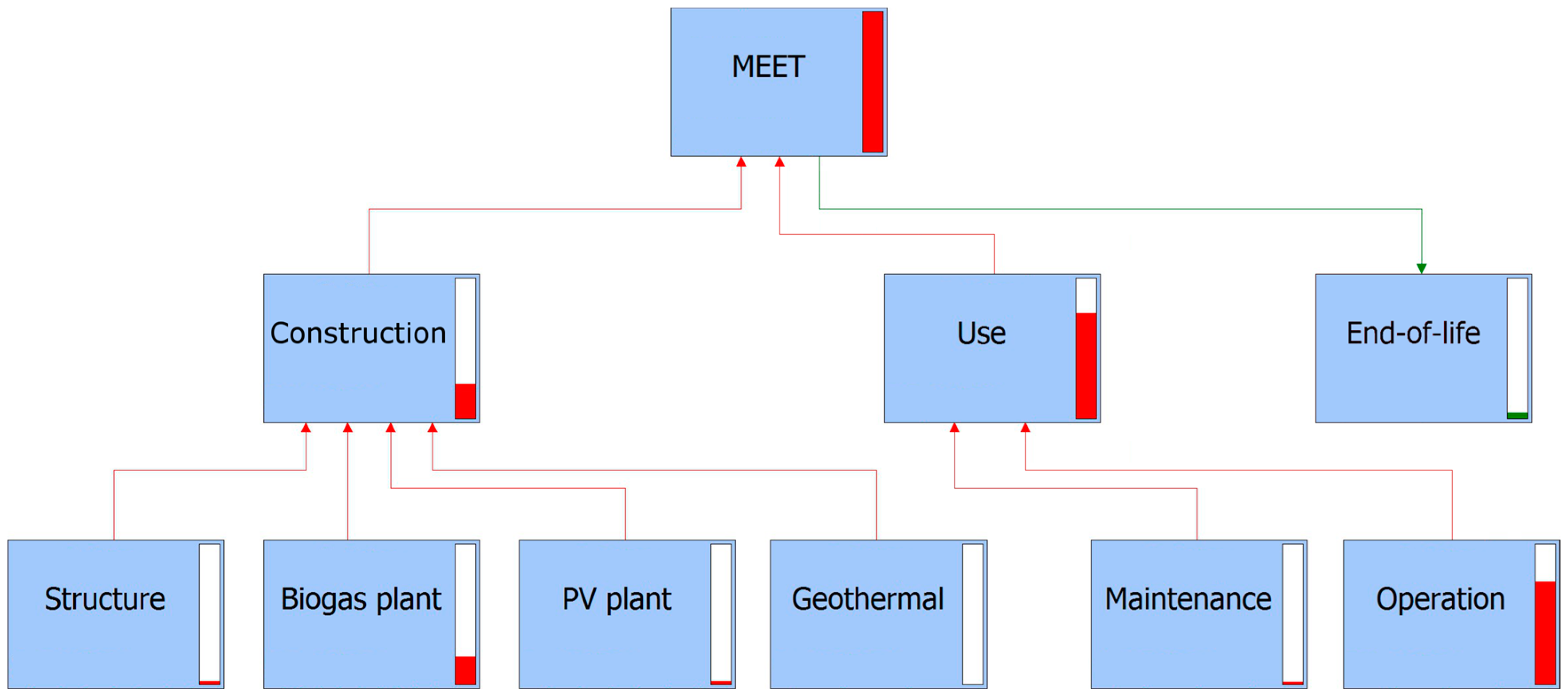
The LCA analysis is structured into three phases: construction, use and end-of-life. The construction phase is composed of four parts: the architecture and structure, the digester plant, the geothermal plant and the photovoltaic plant. The use phase has two components: maintenance and operation (
Figure 3).
Figure 3.
Overview of the life cycle network (down to second-level processes). Red bars show the relative impact of each process.
Figure 3.
Overview of the life cycle network (down to second-level processes). Red bars show the relative impact of each process.
The structure of the MEET consists of square reinforced concrete columns, the reference steel content in pillars, foundation piles, floor and curbs being 200 kg/m
3 [
51]. The digester wall is made of two layers of steel (0.030 m on the inside and 0.002 m on the outside) encasing a layer of polyurethane (0.250 m). The total steel content is approximately 8 tons. Connecting pipes and standard components, normally used in a biogas plant design (
i.e., dehumidifier, gravel filter and solid-liquid separator), are also considered. Electricity self-consumption (11% [
52]) and maintenance of the cogeneration unit is also included. It is assumed that the heat pump has a 10-year lifetime and that it is replaced two times during the MEET life cycle (25 years). The impacts due to the PV plant production, installation and maintenance are also included.
Given the mix of OFMSW (100% biogenic carbon content [
53]) and sewage sludge (14% fossil carbon content [
54]), it is considered that 10.75% of CO
2 emitted during the biogas combustion is fossil, the emission factor being 1.564 kg CO
2/Nm
3CH4 [
55]. A centralized municipal waste collection service within an average distance of 10 km is considered. The organic waste contained in the biodegradable plastic bags is transported to the MEET using motor vehicles. The digestate left at the end of the process is transported with motor vehicles to the final destination (20 km).
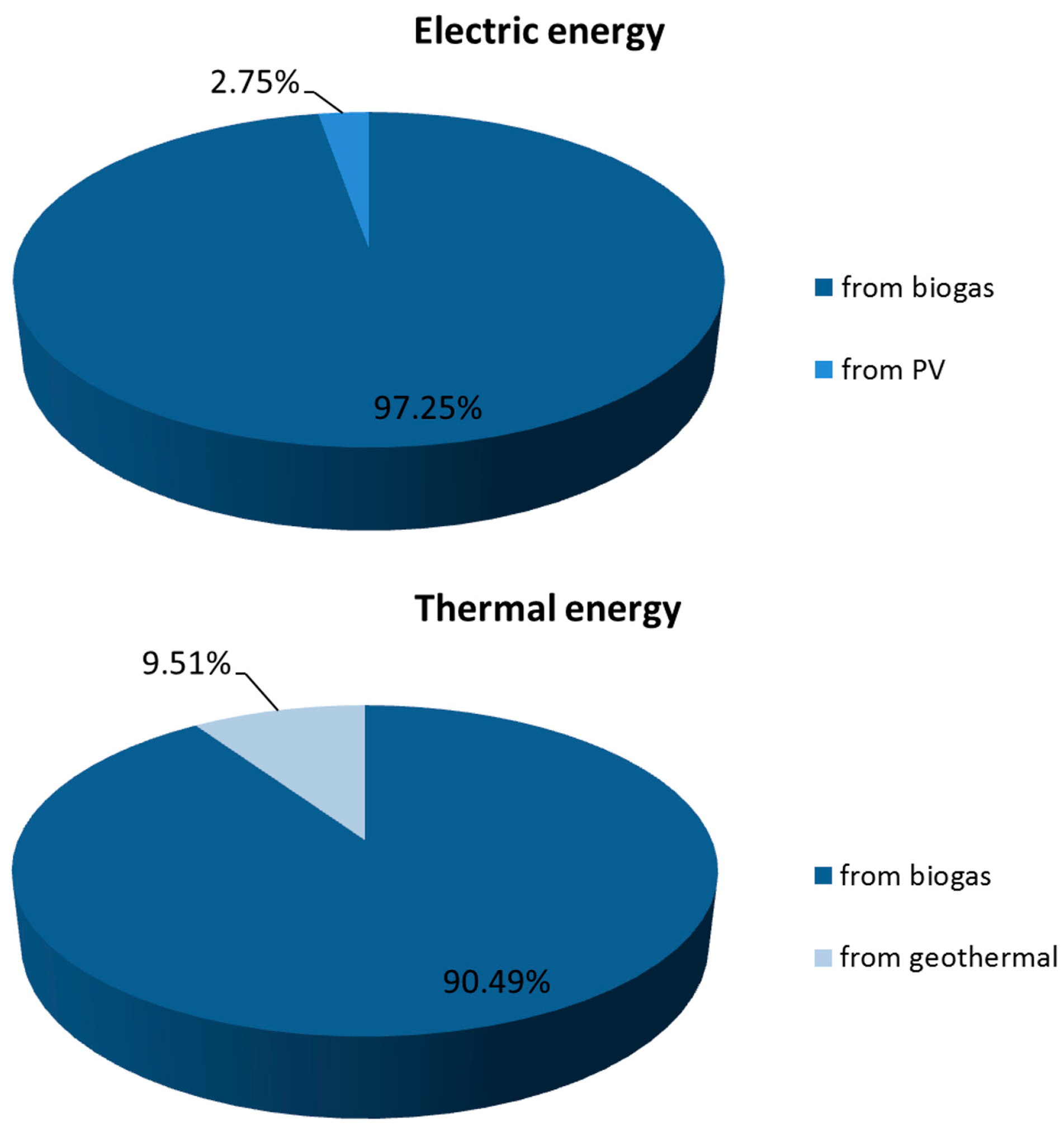
The total net energy production is 9,556,923 kWh/year; 97% of the electric energy and 90% of the thermal energy is produced from biomass (
Figure 4). The net energy production from the biogas plant only is 0.245 kWh per kg of biomass.
Table 2 shows the electric, thermal and total energy produced and consumed by each plant and the energy production as a function of the input biomass.
Figure 4.
Contribution to the production of electric and thermal energy from different plants.
Figure 4.
Contribution to the production of electric and thermal energy from different plants.
Table 2.
Produced, absorbed and net yearly energy.
Table 2.
Produced, absorbed and net yearly energy.
| Biogas plant | Geothermal plant | PV plant | Net |
|---|
| Produced | Absorbed | Produced | Absorbed | Produced | |
|---|
| Electric Energy (kWhe/year) | 5,240,796 | 576,488 | - | 102,857 | 128,859 | 4,690,310 |
| Thermal Energy (kWht/year) | 6,013,813 | 1,610,058 | 462,857 | - | - | 4,866,613 |
| Total Energy (kWh/year) | 11,254,609 | 2,186,545 | 462,857 | 102,857 | 128,859 | 9,556,923 |
| Electric Energy (kWhe/kgbiomass) | 0.134 | 0.015 | | | | 0.120 |
| Thermal Energy (kWht/kgbiomass) | 0.154 | 0.041 | | | | 0.125 |
Considering an average electric energy consumption of 1155 kWh
e/pers/year (2011 data for Italy [
56]), an average thermal energy consumption of 2373 kWh
t/pers/year (2011 data for central Italy [
57,
58]) and a 10% heat loss in the district heating network [
59], the MEET is able to provide enough electric energy to cover 11.6% of the total electric demand and 2.64% of the total heating demand of the urban area served. The latter is obtained assuming that only heat produced during the 6-month heating period is used.
The end-of-life phase (
Table 3) was modeled considering 100% recycling of plastic components and of the above-ground structure (
i.e., 33.2% of the total reinforcing steel and concrete [
51]). No end-of-life processes are defined for the below-ground structure. A 75% recycling of the digester and piping steel is assumed. The end-of-life for other components (e.g., PV parts, heat pump, cogeneration engines,
etc.) is included in the unit process definition.
The calculation in this study is made with the PRé Consultants SimaPro 8.0 software [
60], featuring an optimized calculation engine and including the newly-released ecoinvent 3.0 database [
61], one of the most extensive internationally-recognized life-cycle inventory (LCI) databases. All of the processes were modeled using emission factors from the ecoinvent 3.0 database only, in order to use homogeneous parameters and to obtain uniform results. The standard “allocation, default” attributional modeling approach was used.
Table 3.
End-of-life scenario of the MEET.
Table 3.
End-of-life scenario of the MEET.
| Types of material, disposal scenario | Percentage | Description |
|---|
| Mixed plastics, recycling | 100% | Polycarbonate, polyurethane |
| Waste reinforcement steel, recycling | 33.20% | Above-ground structure a |
| Reinforced concrete, recycling | 33.20% |
| Steel and iron, recycling | 75.00% | Chromium steel (machinery) b |
| Inert waste, for final disposal | 25.00% |
4. Results and Discussion
Impacts are computed for the climate change impact category (carbon footprint) and two land use impact categories (land occupation and land transformation). The functional unit is a mix of electric (0.491 kWhe) and thermal (0.509 kWht) energy that reflects the tower overall production share.
The carbon footprint is calculated with the IPCC 2007 GWP (Global Warming Potential) 100a single-issue method [
62]. Results are compared to current conventional and renewable energy technologies and co-generation plants. As a reference term, the median life-cycle value from all RES ranges from 11 to 74 g CO
2eq/kWh, while that from fossil fuels ranges from 490 to 820 g CO
2eq/kWh [
10].
The land occupation is calculated using the selected LCI results single-issue method [
63]; the land transformation is computed considering the area covered by the MEET during its life cycle, excluding the OFMSW and sewage sludge production and collection, since they can be considered as byproducts currently treated as waste. As a reference, the land transformation associated with energy production from surface mining coal is 487 m
2/GWh, and the land occupation is 1290 m
2year/GWh. Typical values For energy production from biomasses are 17,100 m
2/GWh (ethanol from corn) and 380,000 m
2year/GWh (willow gasification), respectively [
35].
4.1. Carbon Footprint
The annual carbon footprint is 465,390 kg CO
2eq/year, corresponding to 48.70 g CO
2eq/kWh
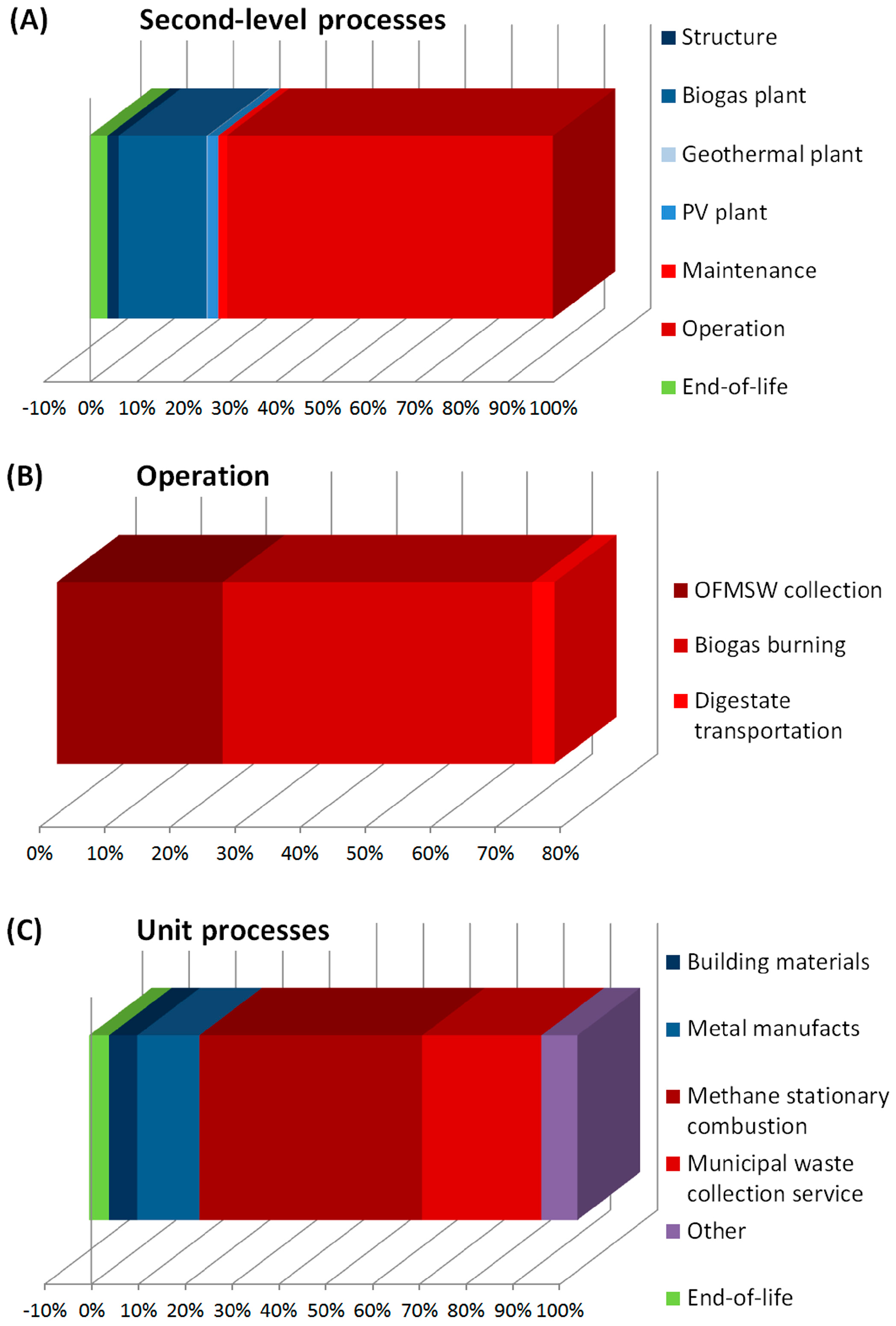
mix. In particular, the contribution of the construction, use and end-of-life phases is 26%, 78% and −4%, respectively. Detailed results are shown in
Figure 5A and in
Table 4.
The two most impacting unit processes (direct emission from biogas burning and OFMSW collection) are within the operation sub-process (
Figure 5B). The former (48% of the total CF) is due to the fossil carbon content of sewage sludge. The latter (25% of the total CF) depends on the high emission factor associated with the municipal waste collection service (stop-and-go driving and on-board hydraulic compression of waste). Detailed results for unit processes are shown in
Figure 5C and in
Table 5.
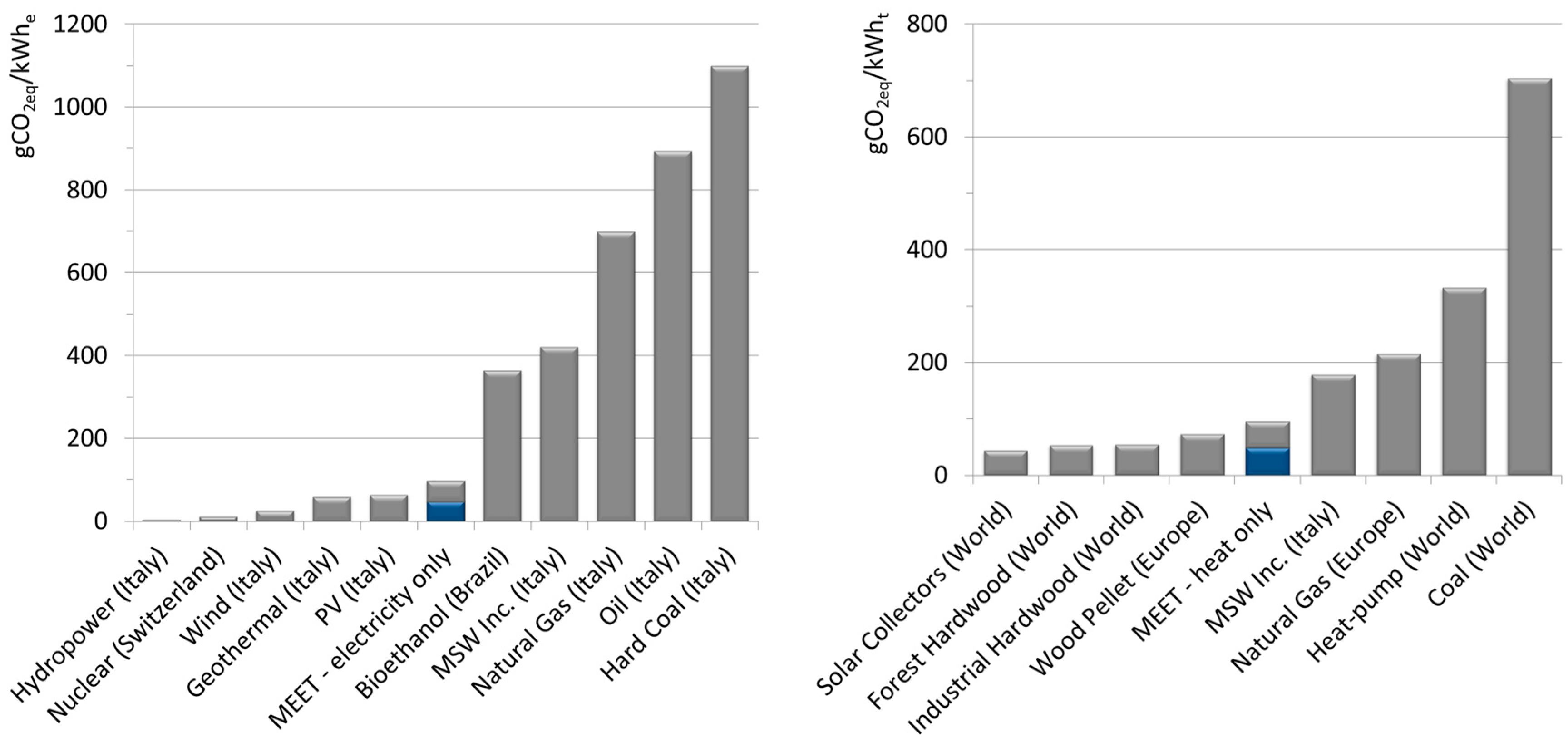
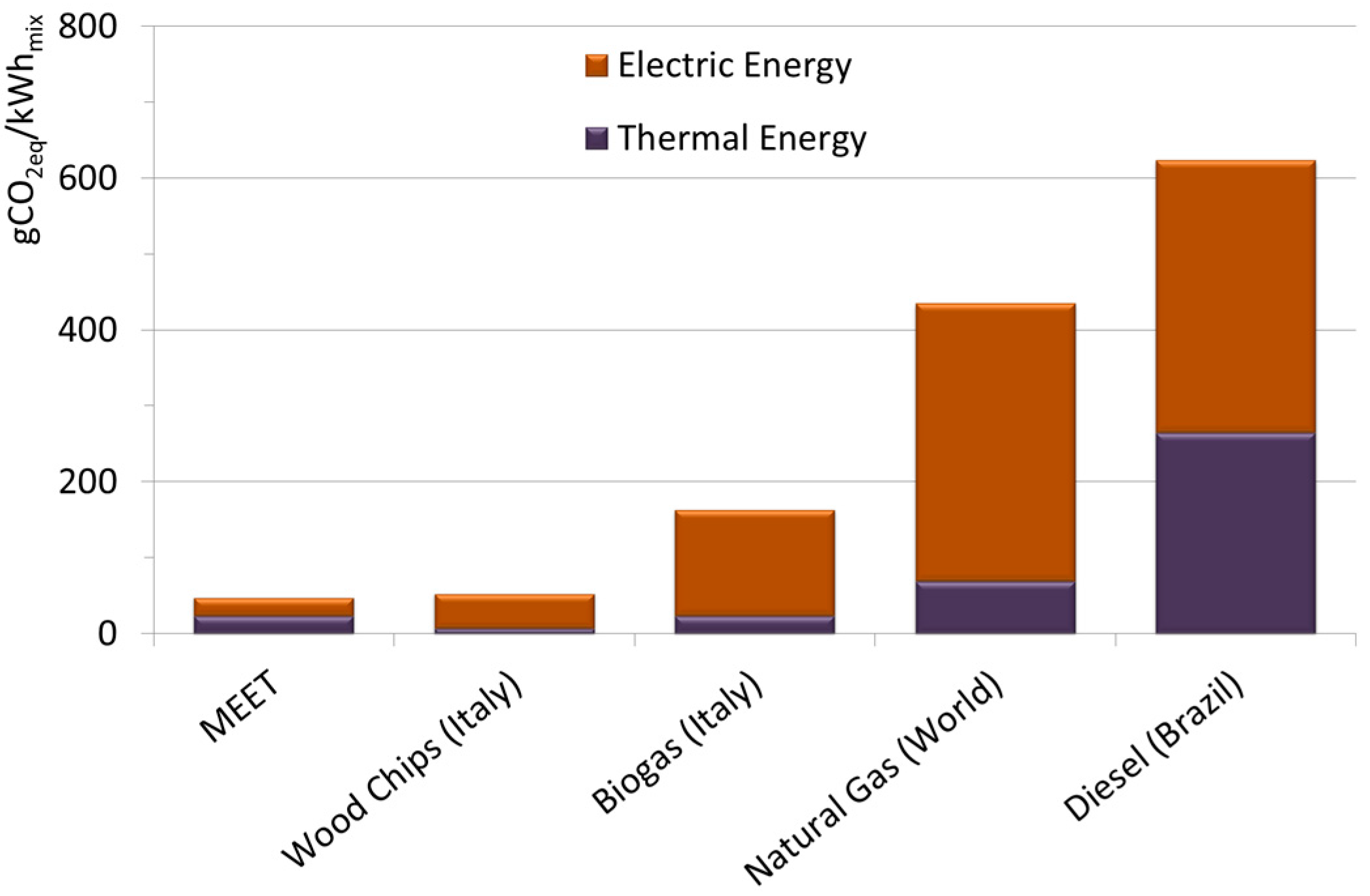
Figure 6 shows a comparison with other electricity and heat production processes in the case that all of the impact is attributed to the power production (left) or heat production (right). Compared to other co-generation processes, the carbon footprint of 1 kWh
mix (49.1% electricity and 50.9% thermal energy) produced by the MEET is lower than conventional and renewable energy sources (
Figure 7).
A sensitivity analysis was performed to evaluate the results dependence over the more impacting parameters: fossil carbon content of sewage sludge, emissions from OFMSW collection and end-of-life scenario (
Table 6).
Figure 5.
(A) Carbon footprint for different LCA sub-processes. (B) Detail of the operation sub-process: collection of organic fraction of municipal solid waste (OFMSW), direct emissions from biogas burning and transportation of digested matter. (C) Detail of the carbon footprint (CF) for unit processes. Some processes are grouped.
Table 4.
Carbon footprint for different LCA sub-processes.
Table 4.
Carbon footprint for different LCA sub-processes.
| Construction | Use | End-of-life | Total |
|---|
| g CO2eq/kWhmix | 12.63 | 38.14 | −2.070 | 48.70 |
| percentage | 25.93% | 78.32% | −4.24% | 100% |
| Structure | Biogas plant | PV plant | Geothermal plant | Maintenance | Operation | | |
| g CO2eq/kWhmix | 1.29 | 10.06 | 0.09 | 1.18 | 0.96 | 37.18 | | |
| percentage | 2.65% | 20.66% | 0.19% | 2.43% | 1.97% | 76.34% | | |
Table 5.
Detail of carbon footprint results for unit processes.
Table 5.
Detail of carbon footprint results for unit processes.
| Unit process | kgCO2eq/year | percentage |
|---|
| Methane stationary combustion | 221,390 | 47.57% |
| Municipal waste collection service | 118,330 | 25.43% |
| Chromium steel | 41,465 | 8.91% | 13.25% |
| Metal working for steel product | 18,400 | 3.95% |
| Chromium steel pipe | 1432 | 0.31% |
| Metal working for chromium steel | 354.5 | 0.08% |
| Metal working metal product | 10.94 | 0.00% |
| Poor concrete | 5997 | 1.29% | 6.05% |
| Reinforcing steel | 21,869 | 4.70% |
| Excavation hydraulic digger | 57.4 | 0.01% |
| Excavation skid-steer loader | 68.53 | 0.02% |
| Building machine | 149.8 | 0.03% |
| Transport freight lorry 16 to 32 metric tons | 15,584 | 3.35% |
| Polyurethane rigid foam | 14,376 | 3.09% |
| Heat and power co-generation unit | 10,775 | 2.32% |
| Maintenance heat and power co-generation unit | 9998 | 2.15% |
| Photovoltaic laminate multi-Si wafer | 8894 | 1.91% |
| Photovoltaic mounting system for facade | 1944 | 0.42% |
| Heat pump | 681.4 | 0.15% |
| Borehole heat exchanger | 543.4 | 0.12% |
| Transport freight lorry >32 metric tons | 508.8 | 0.11% |
| Chipper | 396.2 | 0.085% |
| Inverter | 357.7 | 0.077% |
| Photovoltaic mounting system for flat-roof | 201 | 0.043% |
| Polycarbonate | 190.2 | 0.041% |
| Polyurethane flexible foam | 152.4 | 0.033% |
| Photovoltaic plant electric installation | 90.76 | 0.020% |
| Pump and pumping equipment | 7.146 | 0.002% |
| Dust collector multi-cyclone | 4.843 | 0.001% |
| End-of-life | −19,756 | −4.24% |
| Total | 465,390 | 100% |
The content of fossil carbon in sewage sludge has been set to four different values: 14% (maximum concentration, including industrial wastewater), 7% (maximum concentration from households only), 4% (minimum concentration from households only) and 0% [
54]. As a result, the total CF is reduced down to 25.53 g CO
2eq/kWh
mix (−47.6%).
The emission factor associated with the baseline scenario is much higher than other transportation processes, mainly because of the typical start-and-stop driving and the waste compression using on-board hydraulic machines. Electric vehicles could reduce the total CF down to 39.20 g CO2eq/kWhmix (−19.5%).
The baseline end-of-life model takes into account reference recycling percentages in agreement with the national scenario. Using a no-recycling approach for materials other than plastics would produce an increase of the total CF up to 50.12 g CO2eq/kWhmix (+2.9%).
Table 6.
Sensitivity analysis of the fossil content in sewage sludge (top), OFMSW collection (center) and end-of-life scenario (bottom).
Table 6.
Sensitivity analysis of the fossil content in sewage sludge (top), OFMSW collection (center) and end-of-life scenario (bottom).
| Biogas Burning |
| | Process | Total |
| Scenario | Fossil carbon a | kgCO2eq/year | gCO2eq/kWhmix | percentage | kgCO2eq/year | gCO2eq/kWhmix |
| Baseline | 10.75% | 221,390 | 23.17 | 47.57% | 465,390 | 48.70 |
| Max. content (households) | 5.37% | 110,590 | 11.57 | 31.19% | 354,600 | 37.10 |
| Min. content (households) | 3.07% | 63,223 | 6.620 | 20.58% | 307,230 | 32.15 |
| No fossil carbon | 0% | 0 | 0 | 0% | 244,010 | 25.53 |
| OFMSW Collection |
| | Process | Total |
| Scenario | kgCO2eq/tkm b | kgCO2eq/year | gCO2eq/kWhmix | percentage | kgCO2eq/year | gCO2eq/kWhmix |
| MW collection service | 1.305 | 118,330 | 12.38 | 25.43% | 465,390 | 48.70 |
| 3.5 to 7.5 t Euro 4 lorry | 0.487 | 44,198 | 4.62 | 11.30% | 391,260 | 40.94 |
| Electric vehicles (1 t) c | 0.238 | 21,581 | 2.26 | 5.74% | 374,670 | 39.20 |
| End-of-Life |
| | Process | Total |
| Scenario | | kgCO2eq/year | gCO2eq/kWhmix | percentage | kgCO2eq/year | gCO2eq/kWhmix |
| Baseline | | −19,756 | −2.067 | −4.25% | 465,390 | 48.70 |
| Recycling of plastics only | | −6151 | −0.6437 | −1.28% | 478,990 | 50.12 |
Figure 6.
CF comparison with electricity (
left) and heat (
right) production processes [
61]. The total value (grey) shown for the MEET is obtained assigning all impacts to electricity or thermal energy production, respectively; blue bars mark the contribution per kWh
e (
left) and per kWh
t (
right) once the impact associated with the other form of co-generated energy is discounted.
Figure 7.
Carbon footprint comparison with other co-generation processes for 1 kWh
mix [
61].
Figure 7.
Carbon footprint comparison with other co-generation processes for 1 kWh
mix [
61].
4.2. Land Transformation and Land Occupation
The results of the land use assessment show that the MEET has a very low impact both on land transformation and on land occupation [
35].
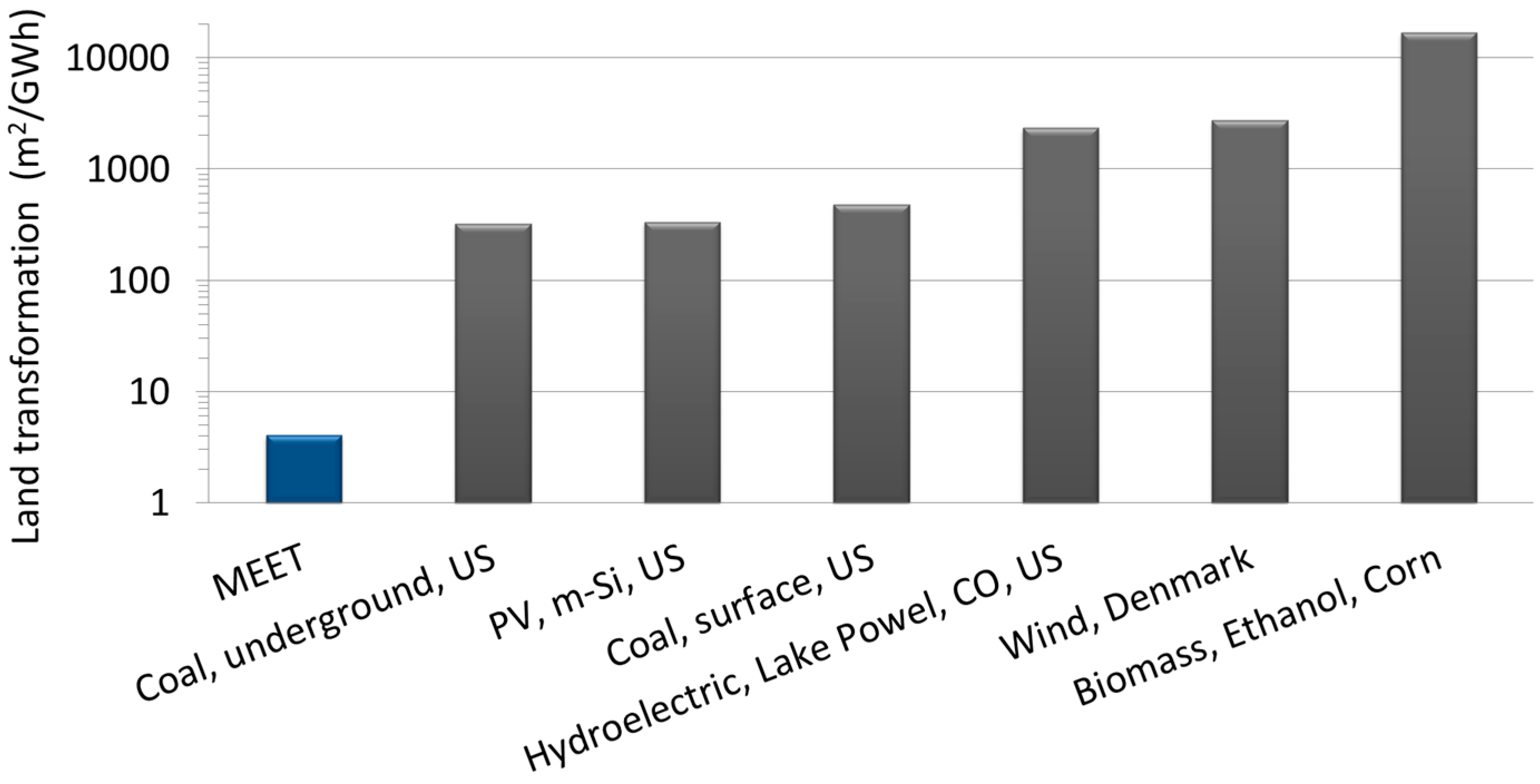
Land transformation is 4.058 m
2/GWh
mix. It is 80-times smaller than underground coal technologies and 4000-times smaller than corn bioethanol. This value was obtained considering a total covered surface of 969 m
2 and no contribution to the land transformation from biomass production, according to the system boundary definition in
Section 3, since both OFMSW and sewage sludge are residues of other activities that are not used in the actual scenario. The comparison with other energy production processes is shown in
Figure 8 and
Table 7.
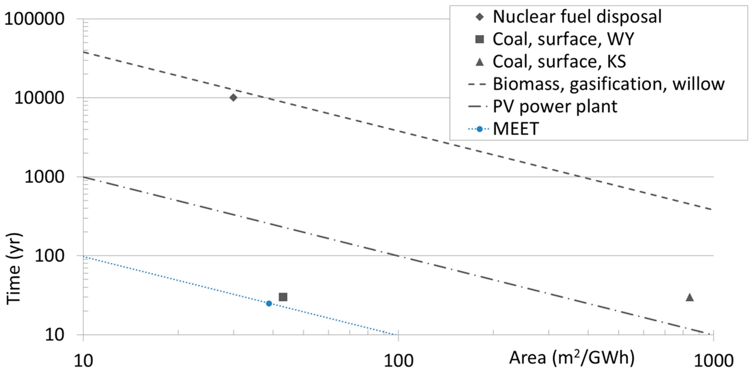
Land occupation is 969.3 m
2y/GWh
mix. The comparison with other energy production processes (
Figure 9,
Table 8) shows that the MEET has the smallest impact. In particular, the land occupation is still lower than the best-performing surface coal technologies and more than 400-times smaller than nuclear and biomass plants. Detailed results for LCA phases and sub-processes are shown in
Table 9. The construction phase produces the largest impact (75%), mainly because of raw materials and the assembly of the biogas digester. Unlike the carbon footprint, the use phase is responsible for only 27% of the land occupation.
Figure 8.
Land transformation compared to other energy production processes [
35].
Figure 8.
Land transformation compared to other energy production processes [
35].
Table 7.
Land transformation compared to other energy production processes [
48].
Table 7.
Land transformation compared to other energy production processes [48].
| Process | Direct (m2/GWh) | Indirect (m2/GWh) | Total (m2/GWh) |
|---|
| MEET | 4.058 | 0 | 4.058 |
| Coal, underground, U.S. | 261.0 | 63.21 | 324.2 |
| PV, m-Si, U.S. | 310.3 | 25.90 | 336.2 |
| Coal, surface, U.S. | 483.9 | 2.786 | 486.7 |
| Hydroelectric, Lake Powel, CO, U.S. | 2350 | 13.60 | 2364 |
| Wind, Denmark | 2755 | 3.670 | 2759 |
| Biomass, ethanol, corn | 16,975 | 124.1 | 17,099 |
Figure 9.
Land occupation compared to other energy production processes [
35].
Figure 9.
Land occupation compared to other energy production processes [
35].
Table 8.
Land occupation compared to other energy production processes [
48].
Table 8.
Land occupation compared to other energy production processes [48].
| Process | m2y/GWh | m2/GWh | years |
|---|
| MEET | 969.3 | 38.77 | 25 |
| Coal, surface, WY | - | 43.00 | 30 |
| PV, power plant | 9900 | - | - |
| Coal, surface, KS | - | 840.0 | 30 |
| Nuclear fuel disposal | - | 30.00 | 10,000 |
| Biomass, gasification, willow | 380,000 | - | - |
Table 9.
Details of the land occupation analysis.
Table 9.
Details of the land occupation analysis.
| Process | m2y | m2y/GWhmix | percentage |
|---|
| Construction | 173,989 | 728.2 | 75.13% |
| Use | 63,520 | 265.9 | 27.43% |
| End-of-life | −5913 | −24.75 | −2.55% |
| Total | 231,596 | 969.3 | 100% |
| Structure | 10,107 | 42.3 | 4.36% |
| Biogas plant | 142,691 | 597.2 | 61.61% |
| PV plant | 20,955 | 87.7 | 9.05% |
| Geothermal plant | 236.4 | 0.9894 | 0.10% |
| Construction total | 173,989 | 728.2 | 75.13% |
| Maintenance | 9886 | 41.38 | 4.27% |
| Operation | 53,634 | 224.5 | 23.16% |
| Use total | 63,520 | 265.9 | 27.43% |
4.3. Discussion
The results for the case study scenario clearly show the MEET potential to reduce the GHG emissions associated with the energy production, in particular when land use is an issue. In general, conservative hypotheses were adopted for the most impacting processes in the reference scenario (maximum content of fossil carbon in the biomass and most impacting collection vehicles for OFMSW), as shown in the sensitivity analysis. Switching to better performing (yet accessible) options could cut the total CF by almost 50%.
The comparison with other technologies was performed using two different approaches. When comparing the impacts of the MEET with other electricity production processes, the impacts for the production of 1 kWh
e, neglecting the production of heat (1.04 kWh
t), is shown (
Figure 6, left). Similarly, the comparison was performed for 1 kWh
t with respect to other heat production processes (
Figure 6, right), which does not take into account the production of electricity (0.96 kWh
e). In both cases, the total CF of the MEET is slightly higher than the least impacting technologies. If, in the comparison, the CF associated with the other form of energy produced is discounted (blue bars of
Figure 6), the impact is lower than or consistent with the least impacting technologies. The second approach (
Figure 7) shows the comparison with other co-generation systems producing the same energy mix. In case of land occupation and land transformation, because of the extremely lower impacts associated with the MEET with respect to other technologies, the overall impact associated with 1 kWh is shown. This simplified approach is motivated by the fact that the production mix is approximately 50% heat and 50% power.
The integration of different renewable energy technologies in a vertical structure allows one to overcome some of the issues, such as land occupation and non-programmability. The performance of the MEET, both in terms of energy production capacity and programmability, could be further extended if other renewable technologies are included in the design. In the current scenario, for example, micro-wind power plants represent a straightforward upgrade of the system. Using a conservative approach, however, they were not included because of strict national regulations on noise and landscape. Similarly, if the energy coverage of the MEET should increase, energy storage systems (e.g., batteries, heat-storage) could be easily included in the vertical structure to guarantee the energy availability when needed. The evaluation of other impacts associated with the MEET, beyond the goal of this work, represents also an interesting future development. In particular, the evaluation of impacts on human- and eco-toxicity and a life cycle costing analysis could provide valuable information. Finally, future development of this work could include systematic studies on other scenarios (i.e., different RES availability, environmental limitations, exploitable technologies) to better understand the potentialities of the MEET.
The limitations of this study are mostly due to the feasibility of the work. Although specific data were used for the plant sizing and manufacturing processes, their homogeneity is not guaranteed, and literature values were used to estimate missing parameters. In particular, no methane leakage was supposed from the digester.
5. Conclusions
The study shows the environmental impact associated with the entire life cycle of the Multifunctional Environmental Energy Tower, an innovative renewable energy system integrating different technologies with the goal of maximizing renewable energy exploitation and minimizing the environmental impact of the energy sector. The performance of the MEET is evaluated in terms of carbon footprint, land transformation and land occupation.
The total net energy production is 9557 MWh/year (4690 MWh
e/year and 4867 MWh
t/year), able to fulfill 11.6% of the total energy consumption and 2.64% of the winter heating demand of the area served. Incineration of the organic fraction of municipal solid waste [
64] would produce, by itself, 4263 MWh
e/year, enough to cover 10.5% of the total electricity demand, but with a much higher footprint in terms of GHG emissions and land use.
The CF, evaluated with the IPCC 2007 GWP 100a single-issue method, is 465,390 kgCO2eq/year, corresponding to 48.70 g CO2eq/kWhmix assuming a 25-year lifetime. Compared to other energy production processes, the CF of 1 kWhmix produced by the MEET (49.1% electricity and 50.9% thermal energy) is consistently lower than most of the conventional and renewable energy technologies. Non-integrated renewable-source power plants (i.e., sand-alone installation), exploitable in an urban context, are characterized by a carbon footprint between 48 g CO2eq/kWht (e.g., heat from biogas cogeneration) to 420 g CO2eq/kWhe (e.g., electricity from municipal solid waste incineration).
The LCA approach allows identifying the most environmentally-critical processes taking place during the MEET life cycle. The contribution of the construction phase is 26% of total CO2 emission; the use and the end-of-life phases are responsible for 78% and −4%, respectively. In particular, the two most impacting unit processes are biogas burning (48% of the total CF) and the OFMSW collection (25% of the total CF). A sensitivity study of the most relevant input parameters is also performed.
The results of the land use assessment show that the MEET has a very low impact from land transformation (4.058 m2/GWhmix) and from land occupation (969.3 m2y/GWhmix). These values, calculated using the selected LCI results single-issue method, are lower than other conventional and renewable energy production processes. In particular, stand-alone renewable plants exploitable in urban contexts, such as PV installations, are characterized by higher values of both land transformation and land occupation (340 m2/GWhe and 10,000 m2y/GWhe, respectively). The construction phase is responsible for the largest impact (75%). However, thanks to the vertical layout and the integration of different technologies, the impact is much lower than other renewable energy technologies and can guarantee an optimal use of land in densely-built urban areas while perfectly integrating with the local architecture.
The MEET represents an innovative solution that can effectively increase the environmental sustainability of urban areas, reducing the carbon footprint and the land use of current energy production scenarios.


