1. Introduction
At present, thick seam (≥3.5 m) accounts for approximately 45% of both China’s reserves and production [
1,
2,
3]. When the coal seam is excavated in the thick seam, there is a greater damage range of roof than that in a normal mining working face (mining height ≤3.5 m). Therefore, the roof structure in thick seam is special and it is more difficult to control the roof. It is an important issue for the working face in thick seam to find out the roof structure and determine the effective support working resistance.
Scholars from China and other countries have done much work on the structure characteristics of the overlying strata at thick seam fully-mechanized faces [
4,
5,
6,
7,
8,
9]. There is a common belief that the equilibrium mechanical structure in the strata will move up as mining height increases. In a normal mining working face, an articulated equilibrium structure in strata can develop. However, with thick seams, the equilibrium structure caves into the goaf. Gong GONG and Jin JIN [
10] divided the immediate roof with thick seams into three types. In the first two types, there is no hanging roof above the goaf. In the third type, the roof hangs above the goaf and fractures in the form of a cantilever beam. Accordingly, a method for calculating an effective support working resistance for types I and III working faces was proposed. On this basis, JU and XU [
11] studied the cantilever beam of the immediate roof motion mode and its effect on the stress at thick seam working faces, according to physical modeling and measured data. They determined the calculation methods for support working resistance under different motion modes.
In China, coal seams with hard roof make up around one third of the total and they distributed in more than half of coal mine areas, with examples being the Datong, Shanxi Yangfangkou and Jincheng coal mine areas. Among these, the Datong coal mine area is the most typical hard roof area in China. No.2, 3, 11 and 12 coal seams in this area are all covered with hard roof [
12,
13,
14,
15]. In the THC, the roof is prone to hang over large areas before it caves and there is a gap between the goaf and the roof. Therefore, its sudden breakage will lead to the support crushing accidents and a wind blast. Therefore, there are severe risks to safety and productivity in the THC.
In China, the research into hard roof control started in the 1950s, and thus has a history of more than 60 years. In earlier stages, maintaining the roof was by using coal pillar support and goaf area backfilling methods. The second stage was to promote and improve roof caving by applying the forced caving method (blasting) and the high-pressure water infusion to weaken the roof [
11,
13,
14]. The two methods are to alter roof’ caving properties. The blasting method can cut off hanging rock block to reduce the caving length each time and create weak roof. The high-pressure water infusion method can destroy the energy storage structure and induce roof caving layer by layer.
The JCM is affiliated with Datong Coal Mining Group, which is situated in Datong city, Shanxi province. No.12 seam of the JCM is a thick seam with hard roof, and #8218 and #8212 are working faces for extracting No.12 seam. Several serious support crushing accidents occurred during mining and had strong impact on safe and productive mining. Therefore, it is of great importance to determine an effective support working resistance and support type and to develop appropriate roof control technology.
2. Analysis on Support Crushing Accidents in Working Face
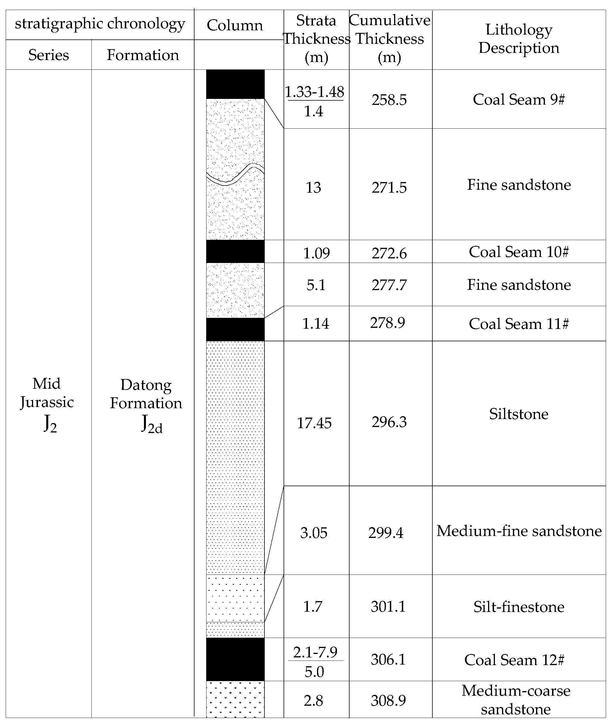
In Panel #402, at the JCM, the seam is relatively undisturbed and the geological structure is simple. The comprehensive column of #8218 working face in Panel #402 is shown in
Figure 1. The seam average thickness is 5.0 m, with average buried depth of 300 m. The seam pitch is 2–10°, averaging 8.0°. There is a 0.5 m rock parting within the seam. The thickness of roof is 22.2 m, which include silt-finestone, medium-fine sandstone and siltstone and the immediate floor is medium-coarse sandstone, as shown in
Figure 1.
The working faces in Panel #402 utilize single-pass mining with thick seam method. The first operation working face is #8218 and the following is #8212. The detail parameters of support can be seen from
Table 1 below. The mining distance of the working face is 1200m; the mining length of the working face is 200 m and the average mining height is 5.0 m.
In #8218 and #8212 working faces, there is no timely caving of the roof during mining. Field observation shows the minimum hanging length of roof is 6 m, the maximum is 13 m and the average is 9.5 m. During the periodic roof weighting period at the working face, the working face roof may impact the support and several crushing accidents have occurred. Among all the accidents, eight of them have had vital impact on production for a total of 81 days. Its characteristics are the following:
- (1)
Roof convergence is high and the supports are often got stuck.
- (2)
End-leakage and rib fall of coal are serious; the maximum rib fall depth can reach 3.2 m.
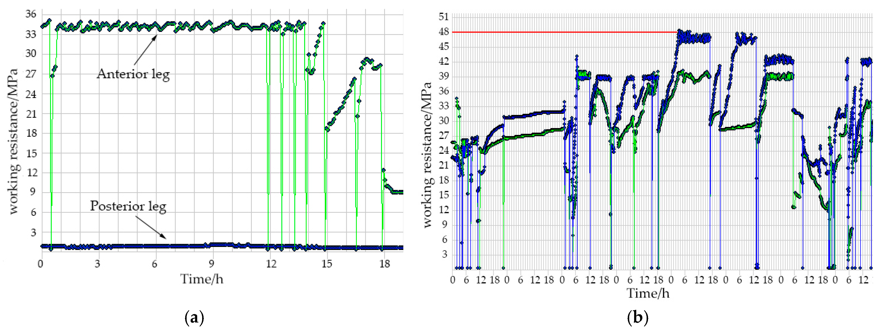
- (3)
Uneven force on anterior and posterior legs. The maximum pressure can be 48 MPa (about 11820 kN), most of the safety valves open. As shown in
Figure 2.
The phenomenon mentioned above shows that the major causes for support crushing accidents are large hanging roof area above working face, insufficient support working resistance and inadequate expansion allowance.
Support crushing accidents influenced the two working faces’ production for 81 days. Daily production of working face is 5000 t and the profit is 200 RMB/t. Thus, the profit loss is 81 million RMB. Meanwhile, support crushing accidents have varying degrees of impact on key equipment, such as the shearer and the supports in the working face. So, additional maintenance is necessary. In
Table 2, support components and their maintenance costs are shown. For the shearer maintenance, 1 drum, 6 slipper pairs, 58 gear rails, 2 hydraulic cylinders, 3 wheel racks, 3 variable-frequency drives, 1890 cable clamps, 1 swing arm for shearer head and tail respectively, 3 cutting motors and 1 traction motor are needed. The total maintenance cost is 584 million RMB.
3. Determining the Effective Support Working Resistance
The effective support working resistance is the ideal working resistance that can ensure safety, profitability and high-efficiency of the working face. It is also the minimum working resistance needed for controlling roof within the sinking range. According to the analysis discussed above, it is necessary to choose the new support type under the conditions of the JCM, so as to prevent the reoccurrence of support crushing accidents. This paper discusses within the context of the #8218 working face in Panel #402, using a theoretical analysis method, to determine the effective support working resistance in the THC.
3.1. The Failure Mechanism of the Roof Strata
It is consequential to understand the failure mechanism of the roof strata and the surrounding rock mass in designing the support system for longwall panel and side entries [
16,
17]. From the early 1970s, the numerical modeling has become a common tool for assessing coal mine ground control problems. If extensive geological and ground control data are available, numerical model can be used to perform a detailed prediction of stress, deformation, and support loads for evaluating the stability of mine structure. If the geological and ground control data are limited, numerical model can be used to perform parametric studies, gaining insight into the possible range of responses of a mine system or subsystems, knowing the likely ranges of the carious parameters [
18].
With the purpose of analyzing the failure mechanism of the roof strata at the JCM with thick seam fully-mechanized faces, RFPA2D [
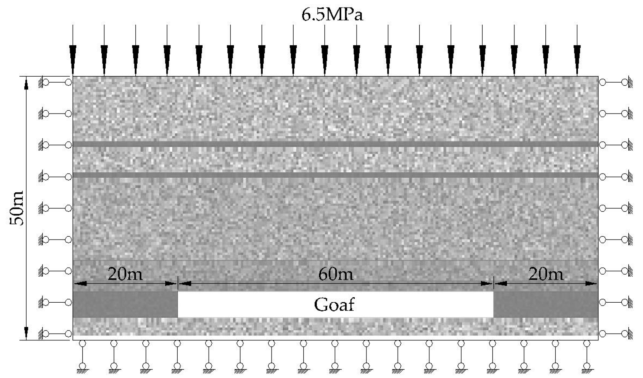
19] has been applied to do contrastive analysis on the strata failure and sliding rule under different mining heights. Based on the background of #8218 working face, a numerical analysis model was established, as shown below in
Figure 3.
The specific boundary and loading conditions for this model are shown in
Figure 3. Both sides and bottom of the model are fixed and there is uniform load (6.5 MPa) at the top.
Table 3 gives a set of properties of mining strata and calculating parameters. The Weibull function is applied in this software to allocate material properties in a heterogeneous extent. The finite element method is employed to obtain the stress fields in the mesoscopic elements. Elastic damage mechanics is used to describe the constitutive law of the meso-scale elements when the maximum tensile strain criterion and the Mohr–Coulomb criterion are utilized as damage thresholds. The model has a meshing scheme of 100 × 200 = 20,000 quadrilateral finite elements.
To form the goaf in the model, it was excavated with 12 steps in 5 m/step. In each step, the property of excavated part was changed from coal seam to cavity to simulate the coal mining before the model starting to calculate. The property of the cavity in this software is default, as shown in
Table 3.
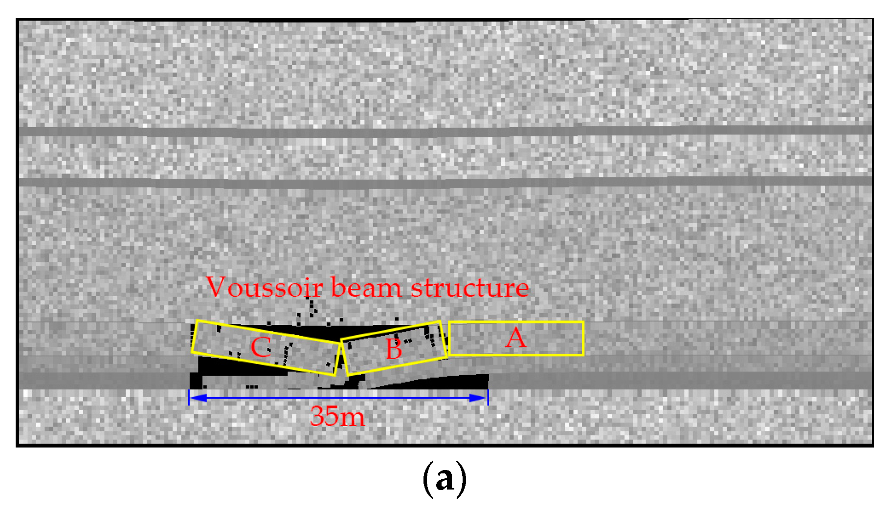
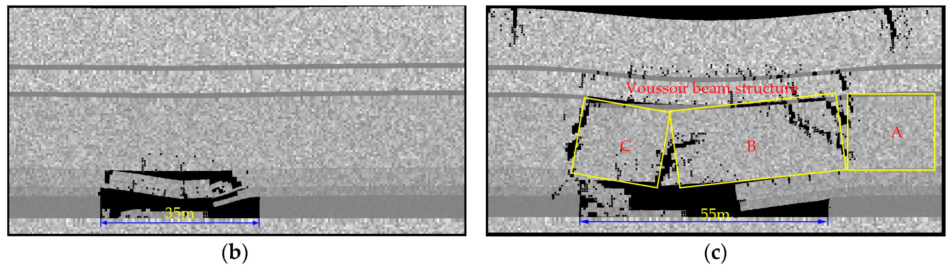
Figure 4 shows that the overlying strata failure and sliding characteristic under different mining heights. During the mining process, if the mining height is 2 m, 3.05 m medium-fine sandstone forms a voussoir beam structure when the working face advances as far as 35 m. It displays obvious roof separation due to the 17.45 m silt-finestone being very thick and having good stability (shown in
Figure 4a). When the mining height is 5m and the working face advance distance is 35 m, 3.05 m medium-fine sandstone fails to form a stable structure due to the large goaf area. When the mining advance distance reaches 55 m, 3.05 m medium-fine sandstone breaks in the form of cantilever beam and 17.45 m silt-finestone breaks and forms stable voussoir beam structure (shown in
Figure 4b,c).
As shown in
Figure 4c, the hanging length of the 3.05 m medium-fine sandstone is about 20 m. During the mining process, the hanging length behind the supports is about 10.13 m on average and the length of the support is 5.45 m. So the average hanging length of the immediate roof from the working face is about 15.5 m which is less than 20 m in the numerical model. It is because there were supports in the working face and the supports were ignored in numerical model. The structure form of roof is not affected by the supports, so it can be accepted for qualitative analysis.
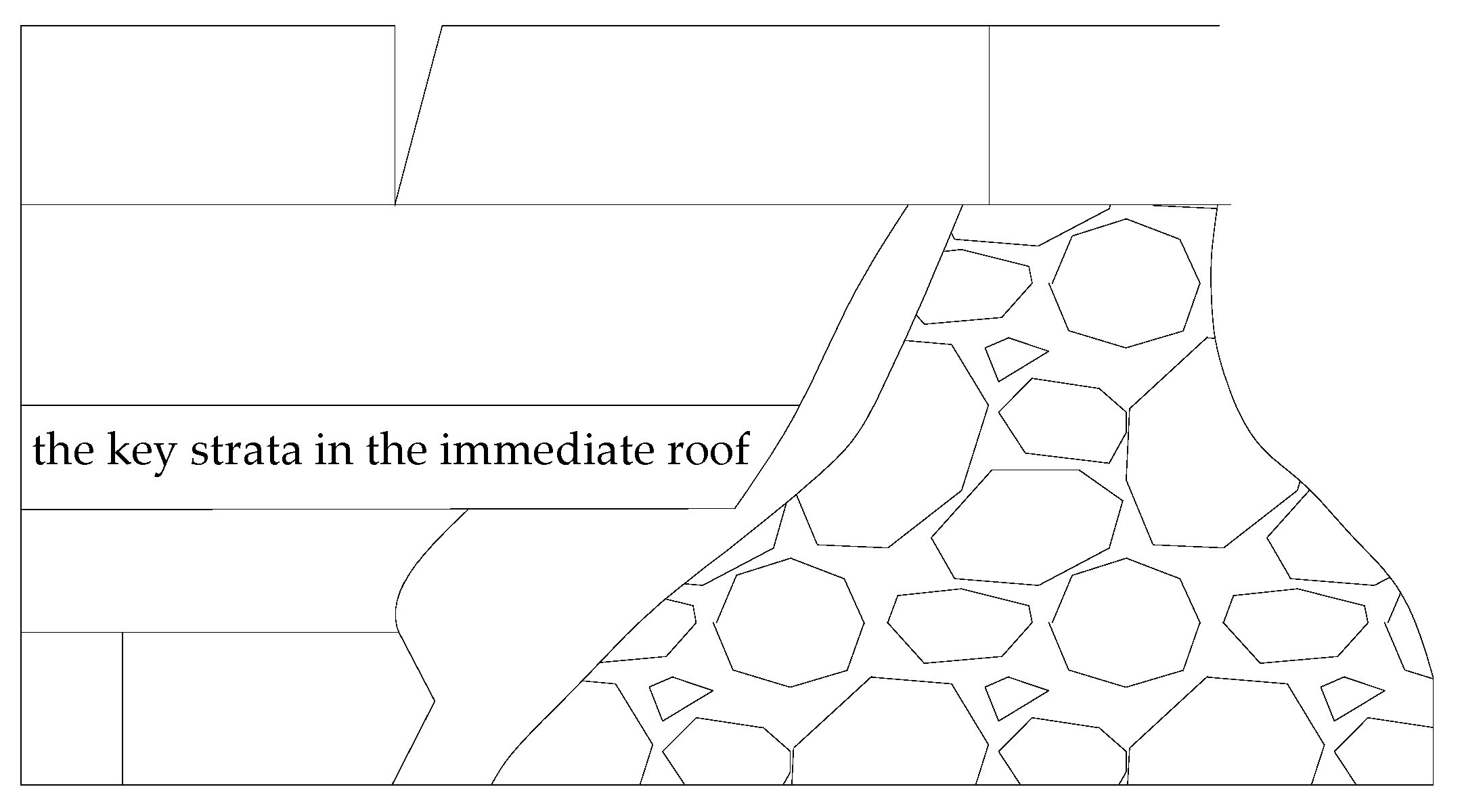
The result of numerical model demonstrated that, as the mining height increases, a voussoir beam structure forms in main roof when mining height is 2 m reaching into the caving zone and finally breaking in the form of cantilever beam. GONG and JIN [
10] defined this type of strata as the key strata in the immediate roof. Although the key strata in the immediate roof cannot hang and form an equilibrium structure, it can break at a certain distance, because of its large strength and thickness, as shown in
Figure 4c. This kind of immediate roof structure is type III mentioned above, which is shown in
Figure 5.
3.2. Stress Analysis on the Key Strata in the Immediate Roof
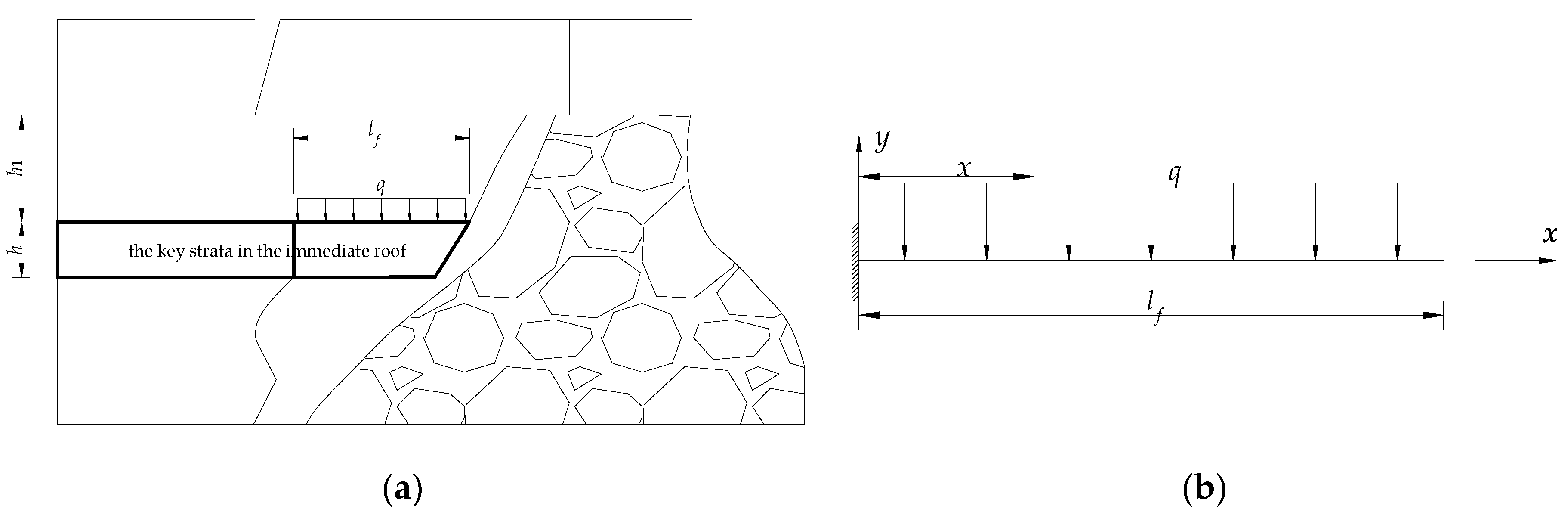
Stress analysis on the hanging key strata in the immediate roof was carried out to determine the maximum hanging length. The state of the hanging key strata in the immediate roof is shown in the following
Figure 6a. Its mechanical model is shown in
Figure 6b.
In
Figure 6a, the stress on the hanging key strata in the immediate roof can be simplified into a cantilever beam model, just as
Figure 6b shows. Determining coordinate system as shown in
Figure 6b, the bending moment on any cross section is:
Where
lf is the hanging length of the key strata, m;
q is distributed load of key strata and immediate roof, N/m;
h,
h1 is the thickness of the key strata in the immediate roof and the overlying immediate roof respectively, m. When
x = 0, the bending moment in this cross section is the maximum, that is to say, the bending moment reaches the maximum when the hanging part is in the support end, with a value of:
The maximum normal stress is:
where
W is the section modulus in bending, and depends on the geometrical shape, m
3. If the cross section is a rectangle with a height of
h and width of
b, the section modulus in bending is:
According to the bending strength condition [
20], with material of different tensile strength and compressive strength (for example, rock), the tensile strength and compressive strength both should not exceed allowable stress.
where, [
σ] is the maximum allowable stress, MPa. For rock, its compressive strength is greater than its tensile strength. So we just need to ensure the maximum stress is no more than its allowable tensile strength
σt.
Combining Equations (1)–(6), the range of the hanging length of the key strata in the immediate roof can be calculated as follows:
Where,
k is the ratio of the thickness of the immediate roof above the key strata to that of the key strata. It is quite difficult to get the rock tensile strength from field measurement. We used the empirical equation to estimate the rock mass tensile strength from compressive strength. Hoek and Brown [
21] derived rock tensile strength depending on rock mass property and practical experience by applying experimental methods.
where
m and
s are constants relevant to lithology and structure planes, and can be obtained from reference literature [
22].
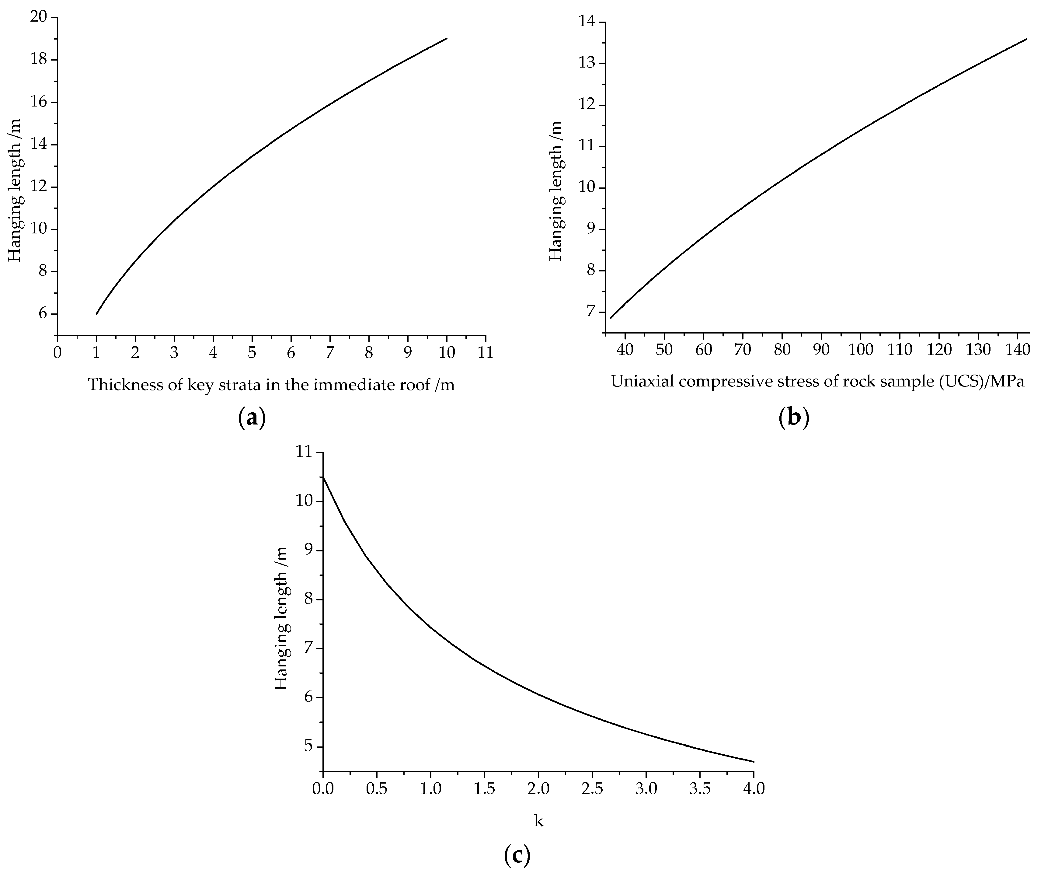
σc is the uniaxial compressive stress (UCS) of rock sample, MPa. By substituting Equation (9) into Equation (7), the range of the hanging length of the key strata in the immediate roof can be written as follows:
According to Equation (10), the relationship between the maximum allowable hanging length of the key strata in the immediate roof and the thickness of the key strata in the immediate roof,
h; and the uniaxial compressive strength of rock sample,
σc; and
k are shown in the following
Figure 7. From
Figure 7,
lf increases with
h and
σc increases and decreases with the increase of
k.
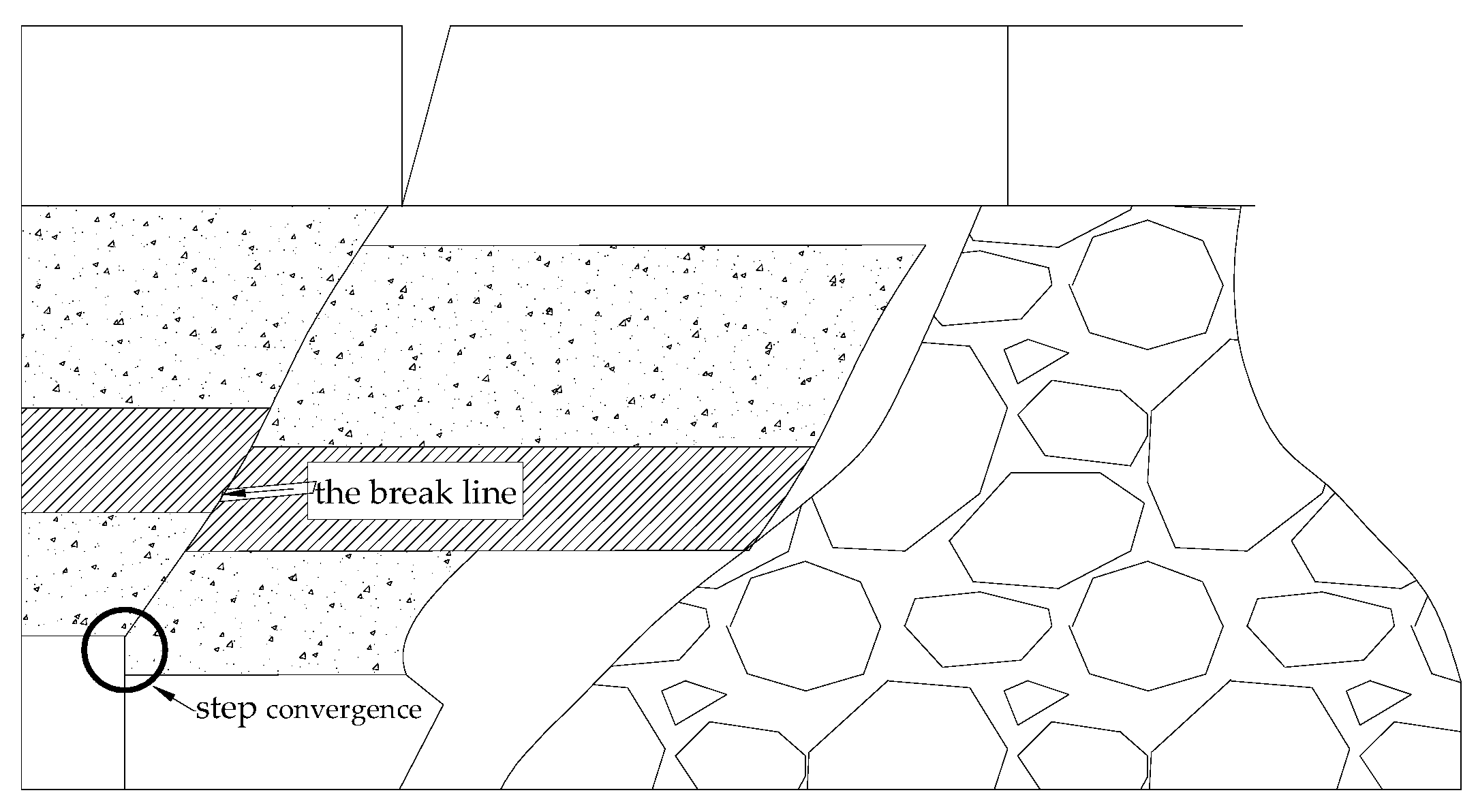
3.3. Determining the Support Load
Support resistance should stop substantial rotation and prevent the key strata in the immediate roof from slipping in the break line, which can lead to step convergence of the working face (as shown in
Figure 8) [
23]. Hence, the most dangerous circumstance is that the key strata in the immediate roof cannot form a hinged structure and became worse when the break line of the key strata in the immediate roof was above the coal face. In this case, support does not only need to support the weight of the immediate roof below the key strata, but also need to sustain the weight of the key strata and the main roof above it. Depending on the above analysis, effective support working resistance can be calculated by the LOEM.
In the design process of longwall mining and the selection of support system, the periodic loading must be considered [
24]. Therefore, the effective support working resistance
P should bear the entire immediate roof weight
Q1 and the additional load caused by the main roof weighting
Q2.
Where hk, lk, γk are the thickness, length and body forces of k-th immediate roof respectively; b is the width of the support.
In normal working conditions, the length of the immediate roof approximately equals the face width. Under thick seam conditions, especially when there is hard roof within the immediate roof strata, if we suppose the length of the immediate roof approximately equals the face width, a large error will occur due to the existence of the key strata in the immediate roof. In this paper, we have taken the hanging length of the key strata in the immediate roof into account to amend Equation (11).
Suppose the hanging length of the key strata in the immediate roof is
lf. Equation (11) will be as follows:
Where hi, li, γi are the thickness, length and body force of i-th immediate roof layer below the key strata in the immediate roof. hj, lj, γj are the thickness, length and body force of j-th immediate roof layer above the key strata in the immediate roof, including the key strata in the main roof. From the known conditions, the length of the immediate roof below the key strata in the immediate roof approximately equals the face width (li = lk). The length of the immediate roof above the key strata in the immediate roof approximately equals to the sum of the face width and the hanging length of the key strata in the immediate roof (lj = lf + lk).
In normal working face conditions, load caused by periodic weighting does not exceed 2 times the normal load [
25]. However, in the THC, there will be an obvious mine pressure increase when periodic weighting occurs due to the strong stability of the roof [
26]. The dynamic pressure coefficient can reach up to 3.5 [
14].
During the mining process of #8218 and #8212 working faces at the JCM, support working resistance was measured by the Uroica fully-mechanized data analysis system, as shown in
Figure 2. The monitoring results were analyzed, using 20 corresponding average working resistance during weighting periods and non-weighting periods respectively and the dynamic pressure coefficient was calculated, as shown in
Table 4.
From
Table 3, in the THC at the JCM, the dynamic pressure coefficient is up to 2.88. So, it can be assumed the dynamic pressure coefficient in the THC is about 3. A working face with hard roof is likely to have a large hanging area and its geological structure is hard to detect at times. In order to ensure that calculation result has a certain margin of error, in consideration of safety and economy, the safety coefficient is adopted as 1.5.
So, we can regard the load during the main roof periodic weighting in the THC to be no more than 4.5 times of the load caused by the key strata in the immediate roof weighting. Hence, effective support working resistance in the THC can be calculated by the following equation:
Based on the above analysis, the effective support working resistance in the THC can be calculated by the following Equation:
3.4. Application Examples
Considering #8218 working face, the thickness of the key strata the in the immediate roof is
h = 3.05 m,
σc for medium fine sandstone is 80 MPa, support face width is
lk = 5.45 m, width is
b = 1.75,
γi ≈
γj ≈ 27 kN/m
3 [
25],
k = 0,
m = 12.5,
s = 0.1. According to Equation (10), the hanging length of the key strata in the immediate roof will be
lf = 10.3 m and this result is in accordance with the field measurement. This shows the validity of the cantilever beam theory being applied to analyzing the key strata in the immediate roof. Based on Equation (14), the effective support working resistance
P is 12,184 kN, and the supporting strength is 1.22 MPa.
3.5. Reasonable Support Type Selection
According to the characteristics of support crushing accidents at the JCM, three requirements are needed for support: (1) Good support cutter top capability; (2) Resisting impact from main roof; (3) Stability during working face weighting period.
In order to satisfy the above requirements, four-leg standing shield hydraulic support is chosen. This kind of support not only has the advantages of standing support, such as, high working resistance, good cutter top capability, large working space; but also has the advantages of shield support, for instance, blocking gangue, good structural stability, good resistance towards thrust from main roof.
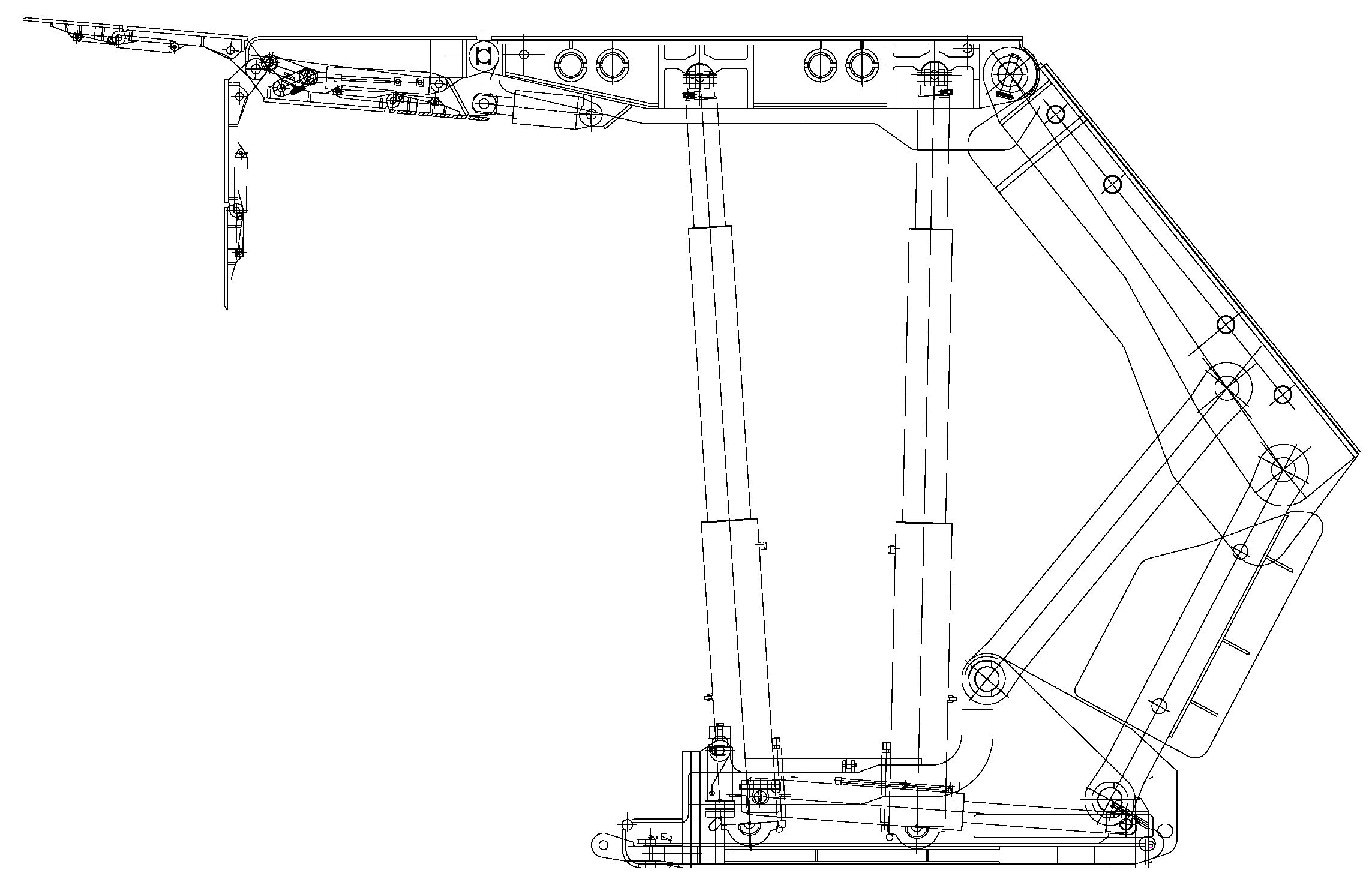
Depending on the above discussion, ZZ13000/28/60 support is determined to be used in the working face. Its working resistance is
P = 13,000 kN; primary supporting force
P0 = 10,128 kN;
P0/
P = 77.9%. The support strength is high, and it has good cutter top capability, and its working resistance and primary supporting force are reasonable. The structure of ZZ13000/28/60 support is shown in
Figure 9.
Table 5 demonstrates the main technical parameters of the chosen support.
4. Supporting Technique for Controlling Large Hanging Hard Roof Area
Under hard roof conditions, large hanging roof area above working face is the main cause for high dynamic stress coefficient. Moreover, for a thick seam working face, the caving roof cannot fully fill the goaf area. There is large space for main roof, and that leads to the increase of dynamic stress coefficient. The average thickness of No.12 seam is 5.0 m, and a conservative estimation is that it needs at least about 9.0 m caving roof to fully fill the goaf area. We can learn from
Figure 1, and assuming the worst condition, that if the 17.45 m silt-finestone cannot cave, the caving roof height can be just 4.75 m and approximate half of the height of the goaf area. In order to fully fill the goaf area with caving roof to decrease the space for main roof and reduce the energy accumulation of the main roof movement, the effective support technique is required.
Essentially, the support technique for hard roof can be divided into two categories, i.e., long borehole high pressure water injection and roof caving by blasting. Long borehole high pressure water injection increases the density of cleats and fractures in roof rock mass, and changes the physical mechanics property to achieve the aim of decreasing the hanging roof area. Four sub-categories are included, i.e., layering water injection, advanced water injection, secondary water injection and goaf water injection. Blasting can increase and propagate weak planes within hard roof and decrease the tensile and shear stress of hard roof to change the mechanical balance conditions. The controlling of periodic weighting distance can be achieved. 5 sub-categories are: loop disposing, intermediate pull out channel caving, the end cut off caving, the DEBT and ground long borehole caving.
In mining engineering, rock fragmentation should be performed with minimum cost and side effects (e.g., ground vibration, air blast, fly rock) [
27,
28]. To achieve this goal, an appropriate blast design should be applied for the loose blasting operation. Taking the technique’s effectiveness and technical level at the JCM into consideration, the DEBT is adopted.
From the above context, the maximum hanging length of the key strata in the immediate roof is about 10.3 m. The break distance of the key strata in the immediate roof is around 16 m, when the support roof control area is taken into account. The DEBT can lead to the timely caving of roof to fully fill the goaf, which then decreases the impact from main roof movement. For safety and economy, the roof caving distance of the working face should be 20 m. Taking into account the existing equipment, lithology of roof and gas content at the JCM, ZYJ-269/168 hydraulic drilling rig and tertiary mine rock emulsion explosive powder are applied.
4.1. The Vertical Length of the Roof Caving Borehole
As immediate roof breaks and falls, its volume increases [
18]. In Panel #402, the caving roof cannot fill the gob. There is a gap between the top of the rock piles and the un-caved stratum. Therefore, to make the gap vanish, the vertical depth of the roof caving hole can be calculated by Equation (15).
where
M is the mining height,
M = 5 m;
K is the broke up coefficient,
K = 1.4; then
HZ = 12.5 m. So, the average vertical length of the roof caving borehole should be no less than 13 m.
4.2. Explosive Consumption
The relationship between per volume rock explosive consumption per volume rock and the blasting face, the rock firmness coefficient can be described by the following equation given by experience [
29]:
where
ke is the explosive correction coefficient,
ke = 1.17;
S is the blasting face area,
S = 13 × 20 = 260 m
2;
f is the rock firmness coefficient,
f = 8;
qem can be calculated to be
qem = 0.23 kg/m
3.
4.3. The Minimum Resistance Line
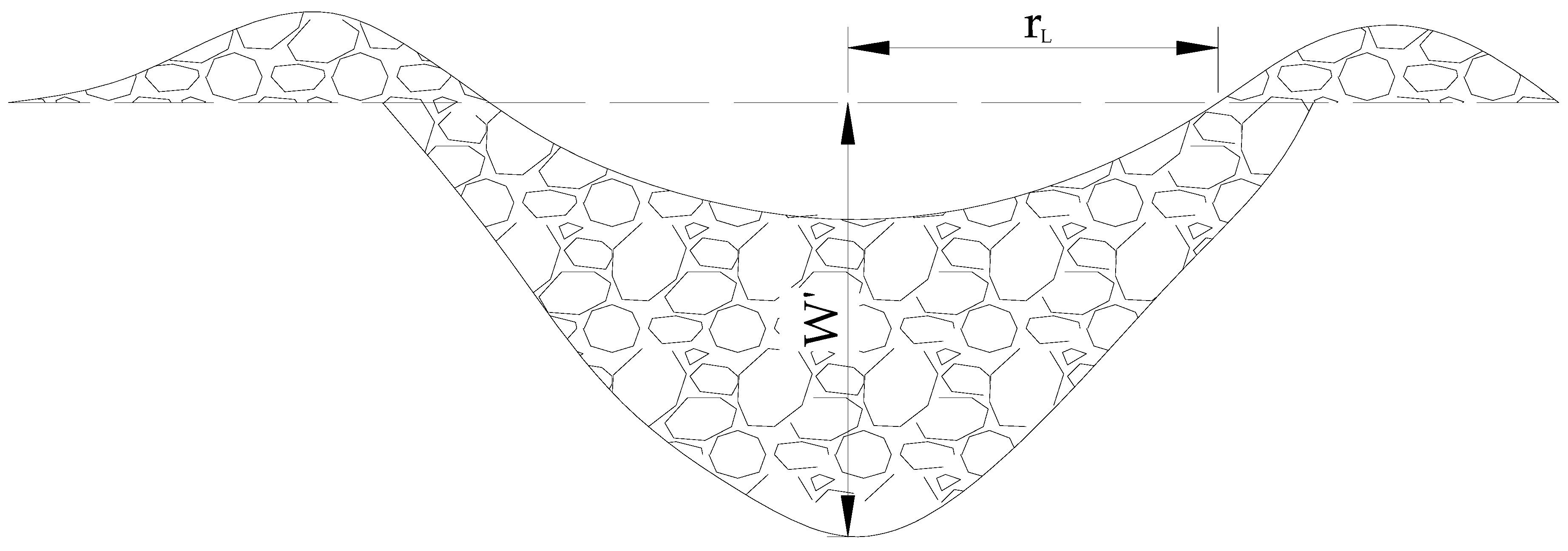
The funnel of the DEBT is shown in the following
Figure 10.
The blasting acting index
n of the blasting is as follows [
29].
where
rL is the funnel radius of standard blasting, mm,
W is the minimum resistance, mm. The range of
n is 0 <
n < 3. When
n < 0.75, there is no blasting funnel. When
n = 0.75, it is called loose blasting. When 0.75 <
n < 1, it is called weak blasting. When
n = 1, it is called standard blasting. When 1<
n < 3, it is called strengthen blasting.
The calculating formula for the minimum resistance line
W is:
where
nL is the blasting acting index of the funnel of the loose blasting
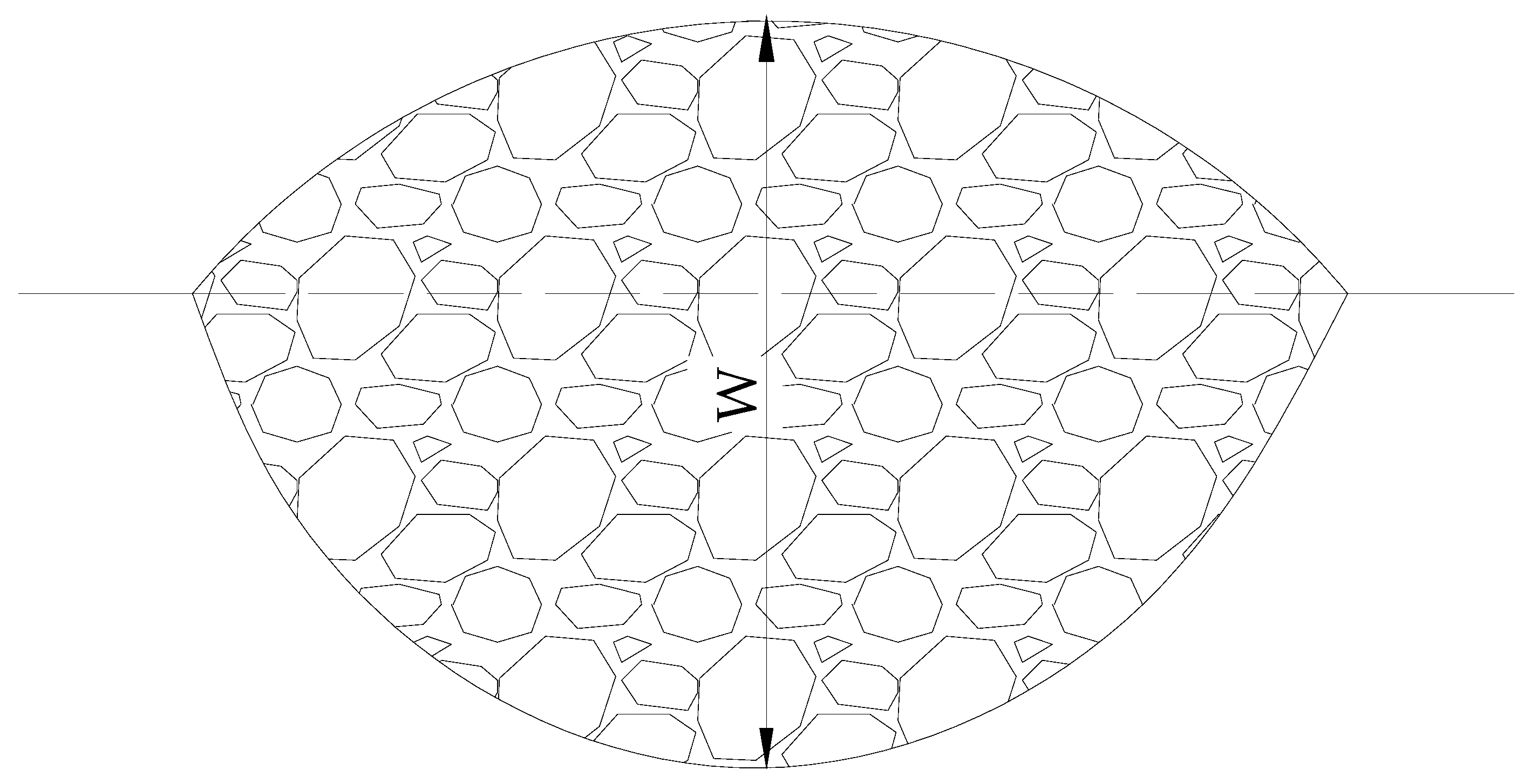
nL = 0.75; The funnel of standard blasting is shown in the following
Figure 11. Its funnel radius is:
where
W′ is the minimum resistance line of standard loosen blasting funnel, mm.
The calculating equation given by experience [
29] for the minimum resistance line of standard loose blasting funnel
W′ is:
where
rb is the charging radius, mm;
ρ0 is the density of explosives, 1018 g/cm
3;
kr is the ratio of charging length to minimum resistance line,
kr = 1.4.
W′ can be calculated and
W′ = 3238 mm. So the minimum resistance line of long borehole loose blasting funnel is 4317 mm.
4.4. The Drill Hole Layout Plan
To avoid affecting the normal production of the working face, roof caving boreholes are put in the two roadways and 50–100 m in advance of the working face; When the caving borehole orifices are at 10 m from the working face coal, production is stopped to do blasting. Combining the above plan and the field conditions, the vertical length of the roof caving borehole is 40 m. Generally speaking, the charging radius of the long borehole loose blasting should not exceed two thirds of the vertical length, so the charging radius is 24 m. In addition to the explosive, the other space of the boreholes is filled with stemming. The length for detonator should not less than 1 m. The schematic diagram of the charge structure is shown in the following
Figure 12.
4.5. The Maximum Charge per Borehole
According to the parameters of the explosive cartridge, the explosive mass per meter is
where
r is the radius of cartridge,
r = 25 mm; so
Gm = 2.0 kg/m, i.e., the maximum charge of the roof caving borehole is 48 kg.
4.6. Parameters of Roof Caving Boreholes around Roadway
The parameters of roof caving boreholes around roadway are shown in the
Figure 13. Where,
α1,
α2 and
β are the vertical angles and horizontal angle of roof caving borehole, °;
L is the length of the roof caving borehole,
L = 40 m;
L′ is the length of the no explosive part,
L′ = 16 m;
L1 is the horizontal length of the roof caving borehole;
A is the length of the support roof beam,
A = 5.1 m; so, according the Equation (22), (23), (24), (25),
α1 ≈ 21°,
α2 ≈ 19°,
β ≈ 7°.
The distress blasting technique is mainly used for controlling the periodic roof weighting interval. The distance between boreholes is determined by the periodic roof weighting interval which can born by the new support.
5. Field Trials
To validate that the chosen support is reasonable and to confirm the effectiveness of the DEBT on hard roof control, we conducted a field trial in #8210 working face of Panel #420. The equipment layout is shown as in
Figure 14. We had utilized Uroica fully-mechanized data analysis system in 7 supports, #10, #25, #40, #55, #70, #80 and #89. The system can record support pressure along with the working face advancing.
During the mining process, average measured primary supporting force is 61.7% of specified primary supporting force. It shows that the primary supporting force could increase to a certain level to make full use of the available supporting force. The maximum measured ending support force is 12,611 kN. The average measured ending support force and the time weighted average force account for 67.2% and 65.7% of the specified working resistance, respectively. The above results demonstrated that the roof of working face is relatively stable and the chosen supports were able to ensure the safety production of the working face.
When the working face advanced 10 m, there was a large-area caving of the immediate roof. The maximum rib fall depth was 200 mm when the immediate roof caved. When the working face advanced 36 m, the first weighting occurred. At this time, the maximum rib fall depth was 300 mm. The average periodic roof weighting interval was 20 m and the roof behind support could cave in time.
ZZ13000/28/60 hydraulic support has double-telescopic feature cylinder that increased the anti-impact ability. During the mining period, no support crushing accidents have happened in #8210 working face. That demonstrates the chosen support is reasonable and the roof support technology is effective in #8210 working face at the JCM.
6. Conclusions
In this paper, the modified LOEM for effective working resistance and the appropriate roof control technology in the THC were presented. The LOEM was modified by considering the hanging length of the key strata on account of the key strata in the immediate roof will break in the form of cantilever beam in the THC. The method for calculating the hanging length of the key strata was put forward and the influence rules of rock property, seam height and the overlying immediate roof height to the hanging length were analyzed. The calculation results are in line with field measurement data and the hanging length of the key strata in the immediate roof increases with the h and σc increase while decreasing with the increase of k. The DEBT is adopted as the roof control technology and the key parameters of the roof caving boreholes were determined. The field trials show that the modified LOEM and the chosen roof control technology are effective and #8210 working face has achieved safe and high-efficient mining.
7. Recommendations and Future Work
In the thick coal seam fully-mechanized face mining with hard roof conditions, it is important to improve the support working resistance and control the hanging length of the roof. The strong working resistance can make the support stable and the small length of the roof can reduce the impact of hard roof.
The future of this research is to test the method of choosing support and the roof support technology on other mining fronts and other mines with similar conditions. In addition, further work would improve the method of choosing support and the control technology of the hard roof.


