Calculation of Limit Support Pressure for EPB Shield Tunnel Face in Water-Rich Sand


1
School of Civil Engineering, Beijing Jiaotong University, Beijing 100044, China
2
College of Civil and Transportation Engineering, Shenzhen University, Shenzhen 518060, China
*
Author to whom correspondence should be addressed.
Symmetry 2019, 11(9), 1102; https://doi.org/10.3390/sym11091102
Submission received: 11 July 2019
/
Revised: 11 August 2019
/
Accepted: 20 August 2019
/
Published: 2 September 2019
Abstract
:With the rapid development of the tunnels constructed under the rivers and seas, the research on face stability of shield tunnel in water-rich sand has important theoretical value and engineering application significance. In addition to the loads exerted by overlaying strata, the tunnels constructed in water-rich strata are usually subjected to high hydrostatic pressure or seepage forces, which are apt to cause the ground collapse of the shield tunnel face. The distribution of hydraulic head field around the tunnel face is critical to assess the impacts of the seepage forces on the tunnel face stability. This paper investigates the axisymmetric problem of the face stability of the shield tunnel under a seepage condition within the framework of limit equilibrium analysis. First, numerical simulations are carried out in this paper to analyze the distribution rules of total hydraulic head and pore water pressure near the tunnel face of the shield tunnel under the condition of stable seepage with different cover depths. Then, based on the distribution rules of total hydraulic head, new formulas for predicting the total hydraulic head along the horizontal and vertical directions are proposed and compared with the numerical simulations in this paper and existing approximate analytical solutions. Second, the classical axisymmetric limit equilibrium model is revised by incorporating the new approximate analytical solutions of hydraulic head field to determine the failure modes and the limit support pressures with a numerical optimization procedure. Lastly, the comparisons of the results obtained from the theoretical analysis model in this paper and the existing approaches are conducted, which shows that the failure mechanism proposed in this paper could provide relatively satisfactory results for the limit support pressures applied to the tunnel face.
1. Introduction
When the shield tunnel locates under the water table line, the soil or rock excavation often induces underground water seepage. The tunnels that are constructed in water-bearing strata are usually subjected to high hydrostatic pressure or seepage forces, which are apt to cause the ground collapse of the shield tunnel face. The key issue during tunneling under the river or sea is to keep the stability of the tunnel face, and this generally depends on the control of support pressure applied on the tunnel face. The pressure must be set at least no less than its limit value, which corresponds to the active failure state of the tunnel face.
The tunnel face stability and the limit support pressures considering the effect of seepage forces were already investigated in previous works with various approaches. The stability of a tunnel face under a seepage condition was studied using experimental tests. To investigate the effect of seepage forces on tunnel face stability, Lee et al. [1] conducted a series of 1 g model tests and obtained the seepage pressure ratios both for the drainage type tunnel and waterproof type tunnel. Tang [2] analyzed the problem of tunnel face stability under the steady state seepage using a laboratory centrifuge apparatus. Lü [3] conducted a series of 1 g model tests to analyze the influences of tunnel depth, seepage, and water level on the limit support pressure of the shield tunnel face and their experimental results were compared with the theoretical predictions. Chen et al. (2018) [4] carried out centrifugal model tests to investigate the face failure of earth pressure balance shield induced by steady state seepage in saturated sandy silt ground. Their results indicated that the limit effective support pressure approximately increases linearly with the increase of the difference of hydraulic head between the ground and the chamber. Numerical simulations were frequently used to investigate the stability of the tunnel face under seepage condition for good reproducibility. De Buhan et al. [5] developed an original numerical method to obtain the distribution of seepage forces in stability analysis of the tunnel face. Ströhle and Vermeer [6] used a nonlinear elastoplastic analysis model to calculate the minimum face support pressure under a simple steady-state groundwater flow. Li and Miao [7] utilized the finite element software ANSYS to investigate the characteristics of the seepage field around a shield tunnel. Lu et al. [8] conducted a 3D elasto-plasticity finite element simulation to obtain the failure modes and the minimum support pressures on the shallow shield tunnel face. Moreover, the heterogeneity of the numerical values of important geo-mechanical parameters makes a big difference on the numerical simulation results [9,10,11].
Analytical approaches including limit equilibrium analysis and limit analysis were commonly applied in the stability analysis of a tunnel face under seepage condition. Anagnostou and Kovári [12,13] adopted the classical wedge-prism model incorporated with the seepage force that is computed numerically by means of 3D steady state flow analyses to calculate the support pressure on the tunnel face based on the limit equilibrium methods. Later on, Perazzelli et al. [14] proposed approximate analytical solutions of hydraulic head ahead of the tunnel face and derive a closed-form solution for the necessary support pressure of tunnel face. Then, Perazzelli et al. [15] extended their model to investigate the tunnel face stability under seepage flow conditions when the tunnel face is reinforced by bolts. Lu et al. [8] modified the wedge model by considering the effect of seepage forces on failure mode, and calculated the limit support pressures of the tunnel face under a seepage condition. Lee and Nam [16] and Lee et al. [1] introduced seepage forces into the upper bound solution of Leca and Dormieux [17]. They calculated the seepage forces with numerical seepage flow analysis and added the seepage forces to the mechanical analysis under a drained condition. Park et al. [18] extended the model of Lee and Nam [16] to the cohesive frictional soil characterized by a linear variation of cohesion with the depth. According to the plastic strain distribution in the collapse state obtained by finite element simulation, Lu et al. [19] proposed a 2D upper bound analysis to calculate the limit support pressure of the tunnel face. Liu et al. [20] adopted a 3D conical mechanism model to investigate the influence of seepage on tunnel face stability.
Based on the complex variable methods, Huangfu et al. [21] derived the analytical solutions for a 2D steady ground water flow into a horizontal tunnel in a fully saturated, homogeneous, isotropic, and semi-infinite aquifer. However, 3D analytical solutions of hydraulic head ahead of the tunnel face are more often required to calculate the seepage forces in the 3D prediction model of the limit support pressures of the tunnel face. In this paper, 2D analytical solutions of hydraulic head ahead of the tunnel face are extended to the 3D condition, which is verified by numerical simulation conducted in this paper.
This paper investigates the problem of face stability of the shield tunnel under a seepage condition within the framework of limit equilibrium analysis. First, numerical simulations are carried out to analyze the distribution rules of total hydraulic head and pore water pressure near the shield tunnel face under the condition of stable seepage with different cover depths. Then, based on the distribution rules of total hydraulic head, new formulas for predicting the total hydraulic head along the horizontal and vertical directions are proposed. Second, the classical limit equilibrium model is revised by incorporating the new approximate analytical solutions of the hydraulic head field to determine the failure modes and the limit support pressures with a numerical optimization procedure. Lastly, the comparisons of the results obtained from the theoretical analysis in this paper and the existing approaches are conducted.
2. Numerical Simulation of the Distribution Rules of the Seepage Field Near the Tunnel Face
2.1. Overview of Calculation of a Hydraulic Gradient around the Tunnel Face
To evaluate the influence of the seepage forces on the tunnel face stability, the key lies in the reasonably accurate estimations of hydraulic head ahead and hydraulic gradient around the tunnel face. In general, the seepage pressures acting on the tunnel face could be calculated via a numerical simulation [1,16] or approximate formula [14,20,22,23].
This paper investigates the problem of the face stability of the shield tunnel under a seepage condition within the framework of upper bound analysis. The distribution of hydraulic head field around the tunnel face is critical to assess impacts of the seepage forces on the tunnel face stability. In order to calculate the seepage force acting on the soil, the distribution of hydraulic head field around the tunnel face should be solved according to the differential equation of water flow. According to Darcy’s law and mass conservation law, a continuity equation of water flow for the groundwater seepage problem in an Equivalent Continuum Theory is a second order partial differential equation. Due to the difficulty in the theoretical analysis of the above formula, in most cases, the distribution of water head near the tunnel excavation surface is calculated by numerical analysis software, and then the seepage force near the excavation surface of the underwater tunnel is calculated. There is a direct relationship between the seepage force acting on the excavation surface of the underwater tunnel and the water head near the excavation surface of the underwater tunnel. When assuming that the underground water seepage follows the Darcy law, the seepage equation in a steady state is as follows.
where kx, ky, and kz are the seepage coefficients in x, y, and z directions. Additionally, h(x,y,z) is the total hydraulic head field.
However, due to the complicated geological conditions and the complex boundary conditions of the tunnel excavation surface, it is difficult to give the exact analytical solutions of distribution of the water head near the excavation surface of the underwater tunnel. To address this problem, many scholars have done extensive research on the distribution of hydraulic head field around the tunnel face, but most of those research studies were conducted through numerical analysis software, especially some more specific cases. Until Perazzelli et al. [14] carried numerical simulation by using the finite element software COMSOL, an approximate analytical solution of the hydraulic head field around a square tunnel constructed in homogeneous stratum under high water pressure is first proposed, which is suitable for earth pressure balance shields and considers that the seepage flow in the horizontal direction of the tunnel face is dominant. The hydraulic head field near the tunnel face and above the tunnel roof can be calculated by Equations (2) and (3), as follows.
where hF is the piezometric head in the working chamber for the case of a closed shield, and △h is the difference between the elevation of the water table h0 and hF. The constants a and b can be determined by curve fitting of Equations (2) and (3) to the numerical results. The specific values of the two parameters under a different ratio of cover depth to diameter of the tunnel should be determined by curve fittings of Equations (2) and (3) to the numerical results and are given in Reference [14]. Compared with the numerical simulations, the approximate analytical solutions proposed by Perazzelli et al. [14] are proved to provide relatively accurate solutions of a hydraulic gradient for the rectangular tunnel [8,23].
The seepage forces per unit volume {fx, fy, fz} are equal to the gradient of the numerically computed hydraulic head h(x,y,z), as shown in Equations (4)–(6).
Furthermore, Table 1 shows the overview of calculating the hydraulic gradient around the tunnel face. icov and icro represent the hydraulic gradient in the cover layer and crossed layer, respectively.
2.2. Finite Element Modeling
In this paper, the finite element analysis software (COMSOL Multiphysics) is used to analyze the distribution rules of seepage field near the shield tunnel face.
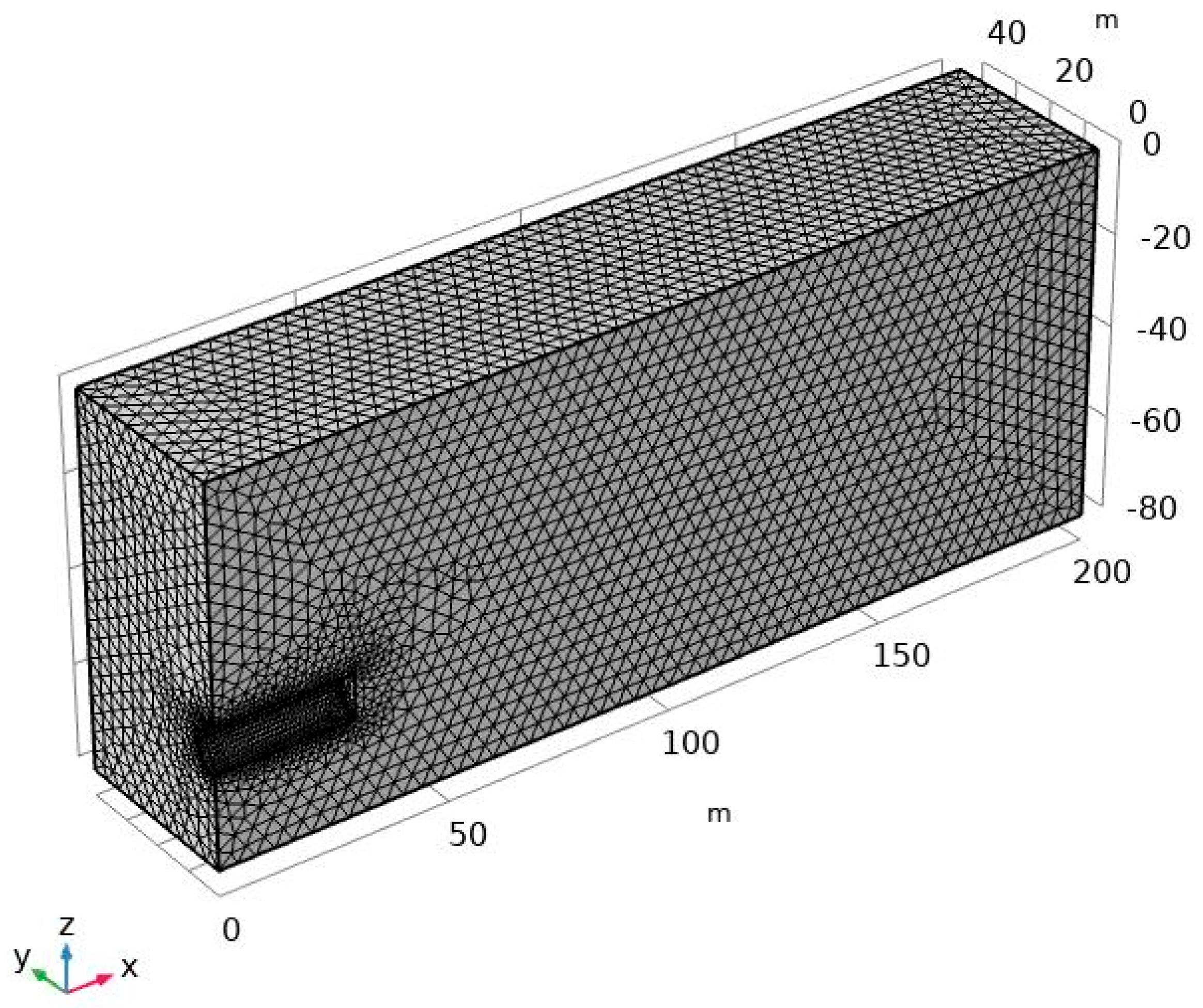
Finite element mesh division is shown in Figure 1. The model has a total length of 200 m, a width of 40 m, and varying height from 40 m to 80 m. The diameter D of the shield tunnel is assumed to be 10 m. In order to analyze the influence of the depth of cover C on the distribution rules of the seepage field, a series of relative cover depth (C/D = 1, 2, 3, 4, and 5) are selected in numerical simulations. The distance h0 between the water surface and the tunnel floor is 100 m. The symmetry of the model is adopted for analysis. Shield tunneling is a progressive process. Considering that the research focus of the distribution rules of the seepage field near the shield tunnel face, the numerical simulation in this paper adopts the one-time excavation to a certain distance (30 m). Boundary conditions of the model are set as follows. The upper surface of the model is fixed pressure, γw(h0-C), the surroundings boundary, bottom boundary, and tunnel liner are impervious boundaries, and the tunnel face is the fixed hydraulic head, htunnel face = 0.
2.3. Seepage Field Analysis
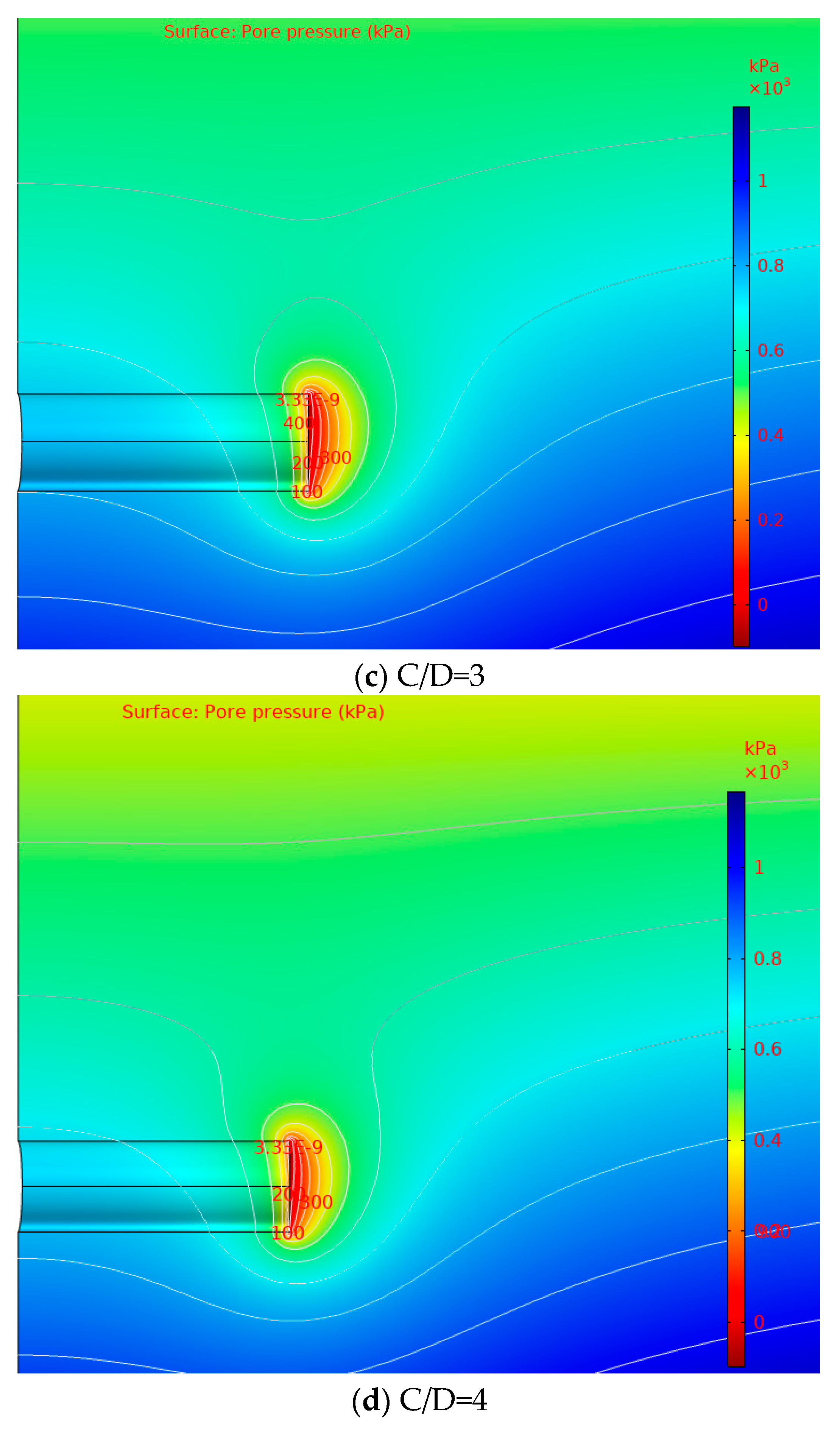
The distribution rules of total head and pore water pressure near the shield tunnel face under the condition of stable seepage are analyzed and discussed under different cover depths, as shown in Figure 2 and Figure 3. It can be seen from Figure 2 and Figure 3 that the seepage field is formed near the tunnel face due to the drainage effect of the shield tunnel face, and the hydraulic slope occurs near the tunnel face.
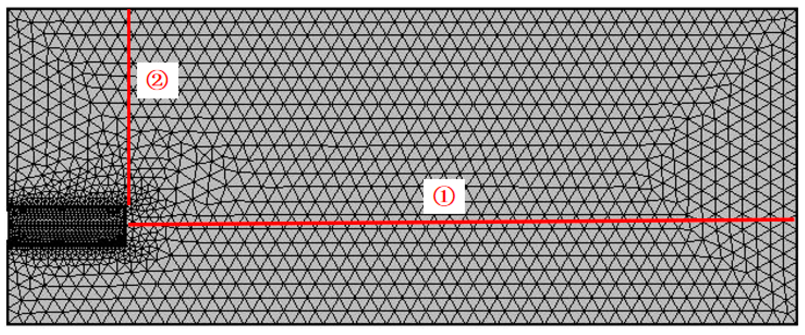
To analyze the distribution laws of seepage field ahead of tunnel face, two measuring lines are defined on the symmetric plane, as shown in Figure 4. A horizontal measuring line (①) represents the axis of the shield tunnel and the vertical measuring line (②) is the vertical line at the tunnel face on a symmetric plane.
Figure 5 and Figure 6 show the total hydraulic head on the horizontal and vertical measuring line under different cover depths, respectively. The distribution law of the total hydraulic head field along the horizontal distance at the axis of the shield tunnel is analyzed. The results show that the distribution of total hydraulic head at the axis of the shield tunnel face along the horizontal distance is a “negative exponential” function, as shown in Figure 5. The distribution law of total hydraulic head along the depth direction of the shield tunnel in front of the tunnel face on the vertical symmetrical surface is analyzed. The results indicate that the distribution of total hydraulic head along the depth is nonlinear when the tunnel is close to the tunnel face, as shown in Figure 6.
2.4. New Approximate Analytical Solutions of Total Hydraulic Head Ahead of the Tunnel Face for the Circular Tunnel
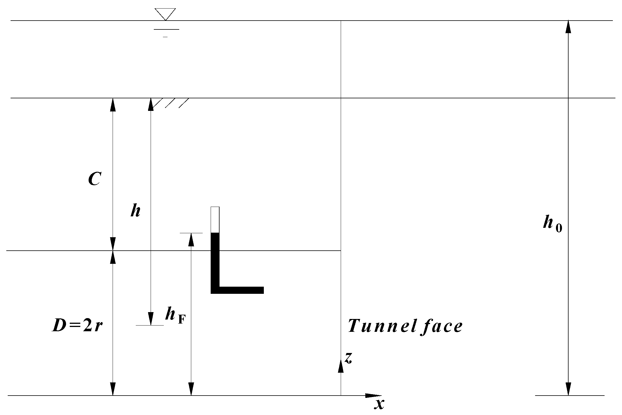
From the results obtained from numerical simulations in this paper and References [14,21], it was found that the distributions of hydraulic head ahead of the tunnel face are independent of ground mechanical characteristics (c’0, φ’0) and are dependent on ground geometric characteristics (i.e., cover depth and radius of the tunnel) and head elevation (hw), which provides a possibility for establishing new 3D formula of hydraulic head field without fitting with the numerical simulations. Figure 7 shows the geometric diagram of the underwater tunnel.
Based on the distribution law of the total hydraulic head field near the shield tunnel face under a stable seepage condition under different buried depths, new formulas for predicting the total head field along horizontal and vertical directions were proposed. New approximate analytical solutions of hydraulic head field ahead of the tunnel face for a circular tunnel are shown in Equations (7) and (8).
where h0 and hF denote the elevation of the water table and hydraulic head on the tunnel face, respectively. Additionally, r represents the radius of the tunnel.
Then the results obtained from Equations (7) and (8) were compared with the numerical simulation in this paper and existing predictions proposed by Perazzelli et al. [14] under C/D = 1 and C/D = 5. Figure 8 and Figure 9 show the comparative results of the horizontal and vertical hydraulic head field, which indicates that those results are very similar with Perazzelli et al. [14] and demonstrates accuracy of the formula provided in this paper. It is worth noting that the numerical simulation and approximate formula proposed in this paper are based on the assumption of the circular tunnel, while the approximate formula in Reference [14] is based on the assumption of the rectangular tunnel.
3. Limit Equilibrium Model of the Tunnel Face Stability Considering the Effect of Seepage Forces
3.1. Outline
The limit equilibrium model composed of a prism and a wedge is illustrated in Figure 10. A tunnel of diameter D is constructed under a depth of cover C. The uniform support pressure σT is applied on the tunnel face to sustain stability. The effective weight of the soil is γ’, the cohesion of the soil is c’, the friction angle of the soil is φ’, and the permeability of the soil is k0. As shown in Figure 8, the wedge is acted upon by the volume forces and the surface forces. The volume forces include its weight and seepage force, while the surface forces include the support force of the slurry on the tunnel face, the resultant normal forces, and shear forces along the failure surfaces ade, bcf, and abfe as well as the resultant vertical force of the prism at the interface defc.
3.2. Mechanical Analysis of the Prism
In the cover layer, the calculation of the distributed force acting on the truncated cone is obtained by modifying the original Terzaghi earth pressure theory considering the vertical seepage forces. Under the assumptions that water level is located at or above the soil surface, the cover layer above the tunnel is homogeneous and the ground in the cover layer obeys the Mohr-Coulomb failure criterion with the cohesion c’ and the angle of internal friction φ′. The vertical equilibrium of an infinitesimal layer read as follows.
where A and L are the area and the circumference of a horizontal cross-section of the prism. icov can be calculated with the Equations (6) and (8).
Because of the complexity of the formula icov, the formula icov is divided into N segments along the depth direction and icov is assumed to be constant in each segment icov,i+1 (). Then Equation (9) can be written as shown below.
Then the vertical stress can be obtained by iteration of Equation (10).
where
.
3.3. Mechanical Analysis of the Wedge
According to the force equilibrium of the wedge:
where Ps is the support force, N is the normal force acting on the surface of the wedge, and G is the gravity of the wedge.
The gravity G is:
The total shear force T on the slope of the wedge is:
The total lateral shear force Ts on the wedge is then obtained:
By Gaussian integration, the volume integral is converted to a surface integral, and the horizontal seepage forces Fx in the wedge block are shown below.
3.4. Calculation of Limit Support Pressure
By solving Equations (12) and (13), the limit support pressure, which is used to stabilize the tunnel face, is calculated by using Equation (18). Then the critical inclination αcr. is determined by iteratively maximizing the necessary support force.
where the coefficients f1, f2, f3, f4, and f5 are:
4. Comparison of the Limit Support Pressures with the Existing Approaches
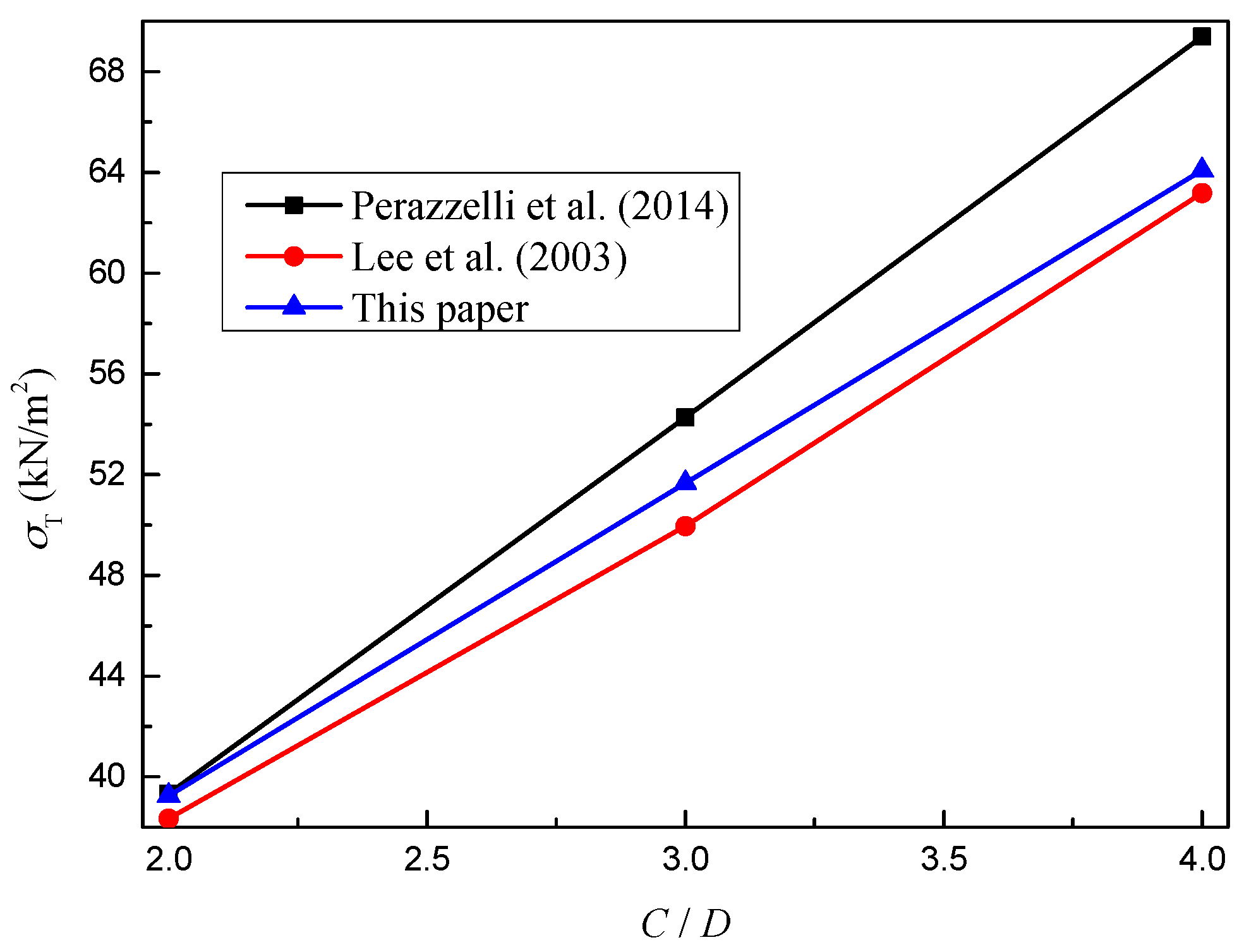
The results obtained from the theoretical analysis model developed in this paper were validated by comparisons with existing approaches (Lee et al. [1] and Perazzelli et al. [14]). The tunnel diameter D is 5 m, and the cover depths C are 10, 15, and 20 m assuming that the water table is located at the soil surface (i.e., h0 = C + D). The cohesion and friction angle of soil are 0 kPa and 35°. The dry and submerged gravities of the soil are 15.2 kN/m3 and 5.4 kN/m3. As shown in Figure 11, the calculated limit support pressure increases linearly with the water table. Moreover, the results from this paper were between the results from Perazzelli et al. [14] (the highest solutions) and from Lee et al. [1] (the lowest solutions).
5. Sensitivity Analysis of Model Parameters on the Limit Support Pressures
5.1. Influence of the Variables of the Hydraulic Head on Limit Support Pressures
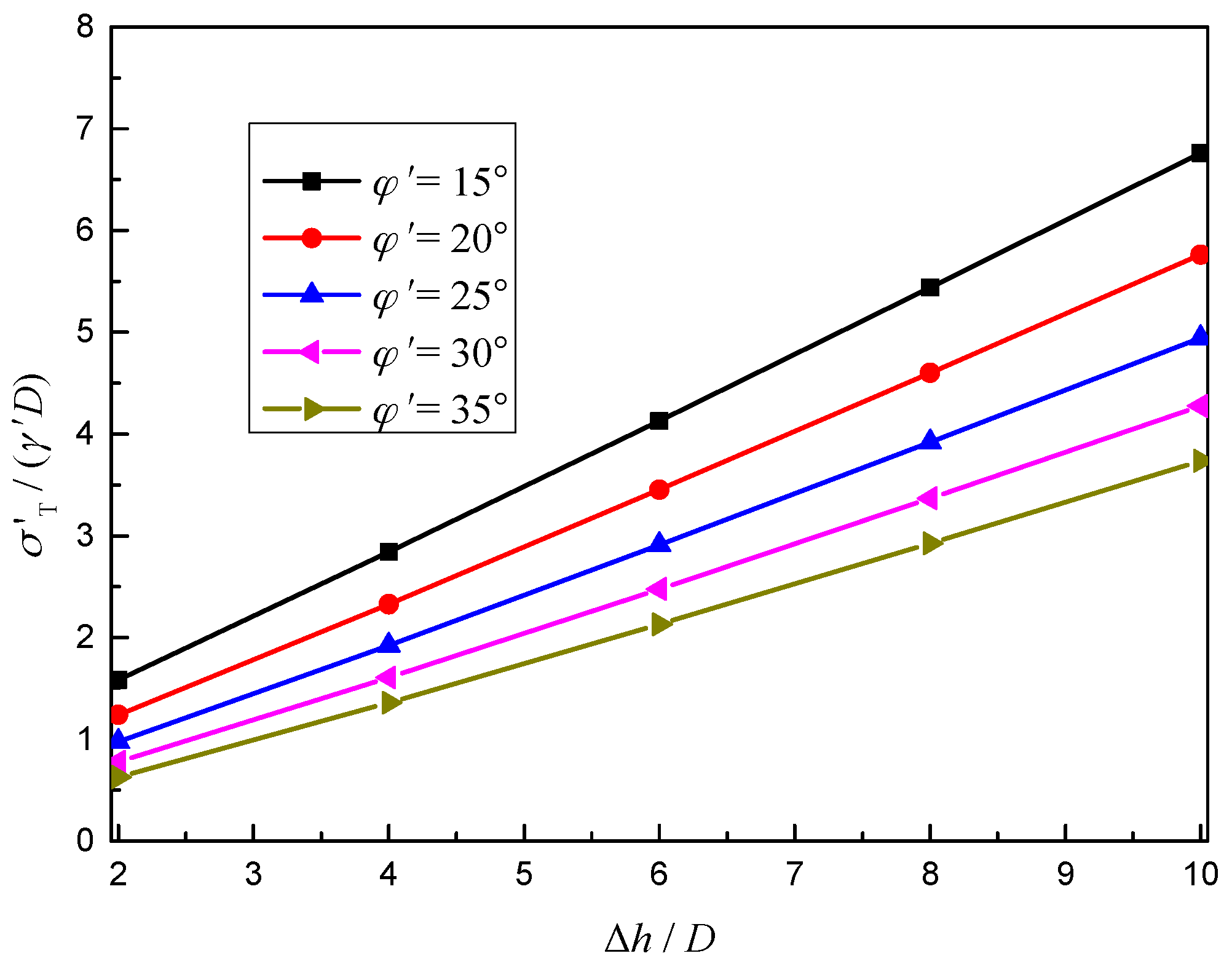
Figure 12 describes the influence of Δh/D on the normalized effective limit support pressures σ’T/(γ’D) with a different effective friction angle of the soil φ’. The tunnel diameter D is 10 m and the cover depth C is 10 m. Hydraulic head h0 are 20 m, 40 m, 60 m, 80 m, and 100 m. The effective friction angle of soil are 15°, 20°, 25°, 30°, and 35°. Submerged unit weight of the soil is 10 kN/m3.
As shown in Figure 12, when the buried depth ratio is the same, the normalized effective limit support pressures of the shield tunnel face increases linearly with the increase of hydraulic head. Moreover, the higher the effective friction angle of the soil is, the lower the normalized effective limit support pressures are.
5.2. Influence of the Variables of the C/D on Limit Support Pressures
Figure 13 describes the influence of C/D on the normalized effective limit support pressures σ’T/(γ’D) with a different effective friction angle of the soil φ’. The tunnel diameter D is 10 m, and the cover depths C are 10, 20, 30, 40, and 50 m. Hydraulic head h0 is 100 m. The effective friction angle of soil are 15°, 20°, 25°, 30°, and 35°. Submerged unit weight of the soil is 10 kN/m3.
As shown in Figure 13, when the hydraulic head is the same, the normalized effective limit support pressures of the shield tunnel face decreases nonlinearly with the increase of the buried depth ratio. It should be noted that, with the same hydraulic head, the small buried depth of the shield tunnel leads to the larger horizontal hydraulic gradient in front of the tunnel face (c.f. Figure 5 or Section 2 in Reference [14]) and the greater the horizontal infiltration force in front of tunnel excavation, which means the larger limit support pressures. Similarly, the higher the effective friction angle of the soil, the lower the normalized effective limit support pressures will be.
6. Conclusions
This paper investigates the problem of the face stability of the shield tunnel under a seepage condition within the framework of limit equilibrium analysis. First, numerical simulations are carried out in this paper to analyze the distribution rules of total hydraulic head, pore water pressure, and a hydraulic gradient near the shield tunnel face under the condition of stable seepage with different cover depths. Then, based on the distribution rules of total hydraulic head, new formulas for predicting the total hydraulic head along the horizontal and vertical directions are proposed and compared with the numerical simulations in this paper and existing approximate analytical solutions. Second, the classical limit equilibrium model is revised by incorporating the new approximate analytical solutions of the hydraulic head field to determine the failure modes and the limit support pressures with a numerical optimization procedure. Lastly, the comparisons of the results obtained from the theoretical analysis in this paper and the existing approaches are conducted. The main conclusions are shown below.
- (1)
- The distribution law of total hydraulic head field along the horizontal distance at the axis of the shield tunnel is analyzed. The results show that the distribution of total hydraulic head at the axis of the shield tunnel face along the horizontal distance is a “negative exponential” function. The distribution law of total hydraulic head along the depth direction of the shield tunnel in front of the tunnel face on the vertical symmetrical surface is analyzed. The results indicate that the distribution of total hydraulic head along the depth is nonlinear when the tunnel is close to the tunnel face.
- (2)
- The comparative results of the horizontal and vertical hydraulic head field with the numerical simulations in this paper and existing approximate analytical solutions demonstrate accuracy of the formula proposed in this paper.
- (3)
- Comparisons of the results of limit support pressure obtained from the theoretical analysis in this paper and the existing approaches show that the failure mechanism proposed in this paper could provide relatively satisfactory results for the limit support pressures applied to the tunnel face.
- (4)
- When the buried depth ratio is the same, the normalized effective limit support pressures of the shield tunnel face increases linearly with the rise of the hydraulic head. When the hydraulic head is the same, the normalized effective limit support pressures of the shield tunnel face decreases nonlinearly with the increase of the buried depth ratio. Moreover, the higher the effective friction angle of the soil, the lower the normalized effective limit support pressures will be.
Author Contributions
L.W. and K.H. conceived of the idea of using a limit equilibrium model and numerical simulation to analyze the problem of the face stability of the shield tunnel under a seepage condition. T.X. and J.L. completed most of the details of the calculations.
Funding
The National Natural Science Foundation of China (Grant no. 51908371) provided financial support for the authors.
Conflicts of Interest
The authors declare no conflict of interest.
References
- Lee, I.M.; Nam, S.W.; Ahn, J.H. Effect of seepage forces on tunnel face stability. Can. Geotech. J. 2003, 40, 342–350. [Google Scholar] [CrossRef]
- Tang, L.J. Numerical Investigations and Centrifugal Model Tests on Face Stability of Shield Tunnel in Dry and Saturated Sandy Soils. Ph.D. Thesis, Zhejiang University, Hangzhou, China, 2014. (In Chinese). [Google Scholar]
- Lü, X.; Zhou, Y.; Huang, M.; Zeng, S. Experimental study of the face stability of shield tunnel in sands under seepage condition. Tunn. Undergr. Space Technol. 2018, 74, 195–205. [Google Scholar] [CrossRef]
- Chen, R.P.; Yin, X.S.; Tang, L.J.; Chen, Y.M. Centrifugal model tests on face failure of earth pressure balance shield induced by steady state seepage in saturated sandy silt ground. Tunn. Undergr. Space Technol. 2018, 81, 315–325. [Google Scholar] [CrossRef]
- DE Buhan, P.; Cuvillier, A.; Dormieux, L.; Maghous, S. Face stability of shallow circular tunnels driven under the water table: A numerical analysis. Int. J. Numer. Anal. Met. 1999, 23, 79–95. [Google Scholar] [CrossRef]
- Ströhle, P.M.; Vermeer, P.A. Tunnel face stability with groundwater flow. In Proceedings of the 7th European Conference on Numerical Methods in Geotechnical Engineering, Trondheim, Norway, 2–4 June 2010; CRC Press (Taylor & Francis): London, UK, 2010; pp. 813–818. [Google Scholar]
- Li, C.L.; Miao, L.C. Finite element simulation of seepage field and analysis of soil deformation around tunnel due to shield tunneling. J. Southeast Univ. (Nat. Sci. Ed.) 2010, 40, 1066–1072. (In Chinese) [Google Scholar]
- Lu, X.; Zhou, Y.; Huang, M.; Li, F. Computation of the minimum limit support pressure for the shield tunnel face stability under seepage condition. Int. J. Civ. Eng. 2017, 15, 849–863. [Google Scholar] [CrossRef]
- Calista, M.; Pasculli, A.; Sciarra, N. Reconstruction of the geotechnical model considering random parameters distributions. In Engineering Geology for Society and Territory; Springer International Publishing: Heidelberg, Germany, 2015; Volume 2, pp. 1347–1351. [Google Scholar]
- Vu-Bac, N.; Lahmer, T.; Zhuang, X.; Nguyen-Thoi, T.; Rabczuk, T. A software framework for probabilistic sensitivity analysis for computationally expensive models. Adv. Eng. Softw. 2016, 100, 19–31. [Google Scholar] [CrossRef]
- Pasculli, A.; Calista, M.; Sciarra, N. Variability of local stress states resulting from the application of Monte Carlo and finite difference methods to the stability study of a selected slope. Eng. Geol. 2018, 245, 370–389. [Google Scholar] [CrossRef]
- Anagnostou, G.; Kovári, K. The face stability of slurry-shield-driven tunnels. Tunn. Undergr. Space Technol. 1994, 9, 165–174. [Google Scholar] [CrossRef]
- Anagnostou, G.; Kovari, K. Face stability conditions with earth-pressure-balanced shields. Tunn. Undergr. Space Technol. 1996, 11, 165–173. [Google Scholar] [CrossRef]
- Perazzelli, P.; Leone, T.; Anagnostou, G. Tunnel face stability under seepage flow conditions. Tunn. Undergr. Space Technol. 2014, 43, 459–469. [Google Scholar] [CrossRef]
- Perazzelli, P.; Cimbali, G.; Anagnostou, G. Stability under seepage flow conditions of a tunnel face reinforced by bolts. Procedia Eng. 2017, 191, 215–224. [Google Scholar] [CrossRef]
- Lee, I.M.; Nam, S.W. The study of seepage forces acting on the tunnel lining and tunnel face in shallow tunnels. Tunn. Undergr. Space Technol. 2001, 16, 31–40. [Google Scholar] [CrossRef]
- Leca, E.; Dormieux, L. Upper and lower bound solutions for the face stability of shallow circular tunnels in frictional material. Géotechnique 1990, 40, 581–606. [Google Scholar] [CrossRef] [Green Version]
- Park, J.K.; Blackburn, J.T.; Ahn, J.H. Upper bound solutions for tunnel face stability considering seepage and strength increase with depth. In Proceedings of the Underground Space the 4th Dimension of Metropolises, Prague, Czech Republic, 5–10 May 2007; pp. 1217–1222. [Google Scholar]
- Lu, X.L.; Wang, H.R.; Huang, M.S. Upper bound solution for the face stability of shield tunnel below the water table. Math. Probl. Eng. 2014, 727964. [Google Scholar] [CrossRef]
- Liu, W.; Albers, B.; Zhao, Y.; Tang, X.W. Upper bound analysis for estimation of the influence of seepage on tunnel face stability in layered soils. J. Zhejiang Univ.-Sci. A 2016, 17, 886–902. [Google Scholar] [CrossRef] [Green Version]
- Huangfu, M.; Wang, M.S.; Tan, Z.S.; Wang, X.Y. Analytical solutions for steady seepage into an underwater circular tunnel. Tunn. Undergr. Space Technol. 2010, 25, 391–396. [Google Scholar] [CrossRef]
- Liu, W.; Zhang, X.J.; Tang, X.W.; Chen, R.P. Supporting pressure for earth pressure balance tunnel face stability when tunneling is implemented in saturated sandy soil. J. Zhejiang Univ. (Eng. Sci.) 2012, 46, 664–704. (In Chinese) [Google Scholar]
- Lei, H.B. Numerical Simulation and Approximate Analytical Solution for Groundwater Flow in Vicinity of the Face of Shield Tunnel Excavations. Master’s Thesis, Beijing Jiaotong University, Beijing, China, 2016. (In Chinese). [Google Scholar]
Figure 1.
Mesh division used for the computation of the hydraulic head field.

Figure 2.
Contour line of the total hydraulic head under different cover depths (h0 = 100 m).


Figure 3.
Contour line of pore pressure under different cover depths (h0 = 100 m).


Figure 4.
Layout of measuring lines in a numerical simulation model.

Figure 5.
Total head on the horizontal measuring line under different cover depths.

Figure 6.
Total head on the vertical measuring line under different cover depths.

Figure 7.
Geometric diagram of the underwater tunnel.

Figure 8.
Comparison of the total hydraulic head obtained from approximate analytical solutions (this paper and Reference [14]) and numerical simulation for C/D = 1.
Figure 8.
Comparison of the total hydraulic head obtained from approximate analytical solutions (this paper and Reference [14]) and numerical simulation for C/D = 1.

Figure 9.
Comparison of the total hydraulic head obtained from approximate analytical solutions (this paper and Reference [14]) and numerical simulation for C/D = 5.
Figure 9.
Comparison of the total hydraulic head obtained from approximate analytical solutions (this paper and Reference [14]) and numerical simulation for C/D = 5.

Figure 10.
Failure mechanism of the tunnel face considering the effect of seepage forces.

Figure 11.
Comparisons of limit support pressure with variation of the C/D ratio.

Figure 12.
Influence of Δh/D on the normalized effective limit support pressures σ’T/(γ’D).

Figure 13.
Influence of C/D on the normalized effective limit support pressures σ’T/(γ’D).


Table 1.
Overview of calculating the hydraulic gradient around the tunnel face.
| References | Hydraulic Gradient | Parameter Specification |
|---|---|---|
| Liu et al. [22] | h0—undisturbed hydraulic head hF—hydraulic head on the tunnel face C—depth of cover D—diameter of the tunnel face | |
| Perazzelli et al. [14] | a,b—constants determined by curve fitting to the numerical results H—height of the tunnel face x,z—vertical and horizontal coordinates | |
| Lei [23] | a,b,c—constants determined by curve fitting to the numerical results r—radius of the tunnel face | |
| Liu et al. [20] | d1,d2—the thicknesses of the cover layers k0, k1—the permeabilities in the crossed layer and cover layer |
© 2019 by the authors. Licensee MDPI, Basel, Switzerland. This article is an open access article distributed under the terms and conditions of the Creative Commons Attribution (CC BY) license (http://creativecommons.org/licenses/by/4.0/).
Share and Cite
MDPI and ACS Style
Wang, L.; Han, K.; Xie, T.; Luo, J. Calculation of Limit Support Pressure for EPB Shield Tunnel Face in Water-Rich Sand. Symmetry 2019, 11, 1102. https://doi.org/10.3390/sym11091102
AMA Style
Wang L, Han K, Xie T, Luo J. Calculation of Limit Support Pressure for EPB Shield Tunnel Face in Water-Rich Sand. Symmetry. 2019; 11(9):1102. https://doi.org/10.3390/sym11091102
Chicago/Turabian StyleWang, Lin, Kaihang Han, Tingwei Xie, and Jianjun Luo. 2019. "Calculation of Limit Support Pressure for EPB Shield Tunnel Face in Water-Rich Sand" Symmetry 11, no. 9: 1102. https://doi.org/10.3390/sym11091102
Note that from the first issue of 2016, this journal uses article numbers instead of page numbers. See further details here.