1. Introduction
The overall development process of electric vehicles consists of many stages, elements, and components, which are characterized by unequal levels of technological maturity. In this regard, the following specific question, which is insufficiently addressed at both the industrial level and in research, can be identified: How to efficiently realize integrated development and testing of electric vehicles (EV) systems from different domains? An additional problem is that, not only is proper electric powertrain design demanded, but also revisiting the automotive chassis design. In particular, the EV motion control requires a blended operation of powertrain and chassis actuators (e.g., brake blending) that motivates at least the following design challenges:
Harmonization of actuation dynamics of EV powertrain and chassis,
Delivering necessary user acceptance of new EV functionalities, and
Addressing more complex requirements to the fault-tolerance and robustness.
Under consideration of these factors, the use of well-established processes in the design of EV systems can have some sensible limitations, for instance, co-simulation issues for software-in-the-loop (SIL)/model-in-the-loop (MIL) procedures, availability of hardware-in-the-loop (HIL) test setups for different systems at the same host, tangible extension of road trial programmes with added time/cost resources to check new functionalities.
The SIL, MIL, and HIL tools together can be referred as X-in-the-loop or XIL. These established XIL technologies are currently being advanced with the development of new classes of design concepts. For example, Albers et al. [
1] proposed an extension of the XIL framework through a connection with the integrated product development model and knowledge management systems, widely used in industrial design processes. Another variant of an XIL tool was introduced by so-called concept of test-rig-in-the-loop (TRIL). The TRIL technique aims at real-time integration of two or more test rigs from, for example, dynamometers and HIL test setup [
2].
For an XIL architecture with test rig communication, more and more efforts are being observed to adopt advanced internet-based technologies. Despite that the first attempts in this field were reported a decade ago [
3], only recent progress in communications has enabled robust solutions in this field. For instance, the corresponding technology for connecting battery, powertrain, and full vehicle test rigs was reported in [
4] as an example of an internet-distributed vehicle-in-the-loop simulation platform for hybrid electric vehicles. Another tool was discussed in [
5] for the X-in-the-distance-loop demonstration platform. This platform consisted of a driver simulator, driving electric motor, and dynamometer test setup, which have been used for bidirectional experiments to test communication of powertrain data between China and Germany. The work [
6], reported an application example of co-simulation for the connection of a scaled test bed (Graz, Austria) and RT driving simulation environment (Renningen, Germany) for validation of functions of advanced driver assistance systems.
An internet-based XIL brings benefits for developers since it allows real-time coupling of various test setups from different hosts. Complex design tasks may require comprehensive validation procedures on many experimental devices, and there is no guarantee that all required equipment is available at the same host or by the same owner. However, some challenges have to be solved in the area of the internet-based XIL to propose corresponding development tools suitable for industrial use. This concerns such issues as pertinence of web communications for real-time simulation and tests as well as operative recovering of the lost information during test data exchange. As was demonstrated in previous studies from authors of this paper [
7,
8], dedicated to real-time brake control experiments between Germany, the Netherlands, the USA, and South Africa, remote and distributed XIL procedures require consideration of many factors to avoid serious limitations to feasible test scenarios.
In line with previous investigations, we propose a new approach, called XILforEV, that aims at developing a connected and shared X-in-the-loop experimental environment uniting test platforms and setups from different physical domains and situated in different locations. The domains under discussion can cover (but are not limited to) hardware-in-the-loop test rigs, dynamometers, software simulators, driving simulators, and other variants of experimental infrastructures. The real-time (RT) running of specific test scenarios simultaneously on (i) all connected platforms/devices with (ii) the same RT models of objects and operating environments allows exploring interdependencies between various physical processes that can be hardly identified or even expected in the design development stage. In the long-term perspective, the plug-in concept of including various test platforms/devices and easy on-demand access to the test procedures for developers, engineers, and researchers will bring a vast impact to the EV design community through connecting experimental environments around the world.
The next sections of the paper will introduce the XILforEV architecture, its modelling components, as well as formulation of four dedicated case studies.
2. XILforEV Architecture
The proposed architecture has been originated from the following set of requirements:
Purpose—provide an experimental environment for simultaneous RT validation and testing of EV powertrain and chassis systems using connected facilities distributed between different geographical locations;
Functionality—use for development design of EV control systems, studies on fail-safe operation, and investigations on synergetic effects from the integrated operation of EV systems;
Networking—consider variants of distributed local (test setups are located in the same host and can be connected by a local network) and distributed remotely (test setups are located in different geographical hosts and connected by the internet);
Global modelling—use of one global server-based or cloud-based RT vehicle model for all networked testing facilities; and
Open interface—allow inclusion of any required new test setups into the architecture with the access for external users.
An overall approach to the XILforEV architecture can be explained with
Figure 1. This architecture allows developing the EV subsystem controllers in a realistic environment by leveraging the use of existing facilities. In particular, MIL tools are used for full vehicle simulation in a virtual environment. The SIL technique is applied for investigations on functional reliability of embedded software applications. TRIL is represented by different test setups, which could generally include dynamometers, driving simulators, and other experimental devices. The TRIL and HIL components are connected using real-time communication (RTC). It should be noted that this architecture supposes a plug-in interface allowing flexible inclusion of different test devices depending on the development task.
The XILforEV utilizes a variety of XIL approaches in vehicle, driver, and subsystems testing, considering them in one control loop. Such an approach is an effective tool for the rapid development and testing of the vehicle as a complete system or as its integrated components. First of all, the following design tasks can be considered here:
Subsystem parameters identification;
Development of the real-time plant model;
Implementation of the developed software systems to the hardware-in-the-loop platform and TRIL environment; and
Integration of powertrain and chassis subsystems, especially in the case of a multi-actuated electric vehicle.
It should be noted that the proposed approach in general can be applied to vehicles with different powertrain variants. However, within the framework of the discussed study, the vehicle configuration with individual in-wheel motors has been selected. This is caused by target development tasks such as brake blending and ride blending designs, where in-wheel motors are used as actuators together with the friction brake system and active suspension.
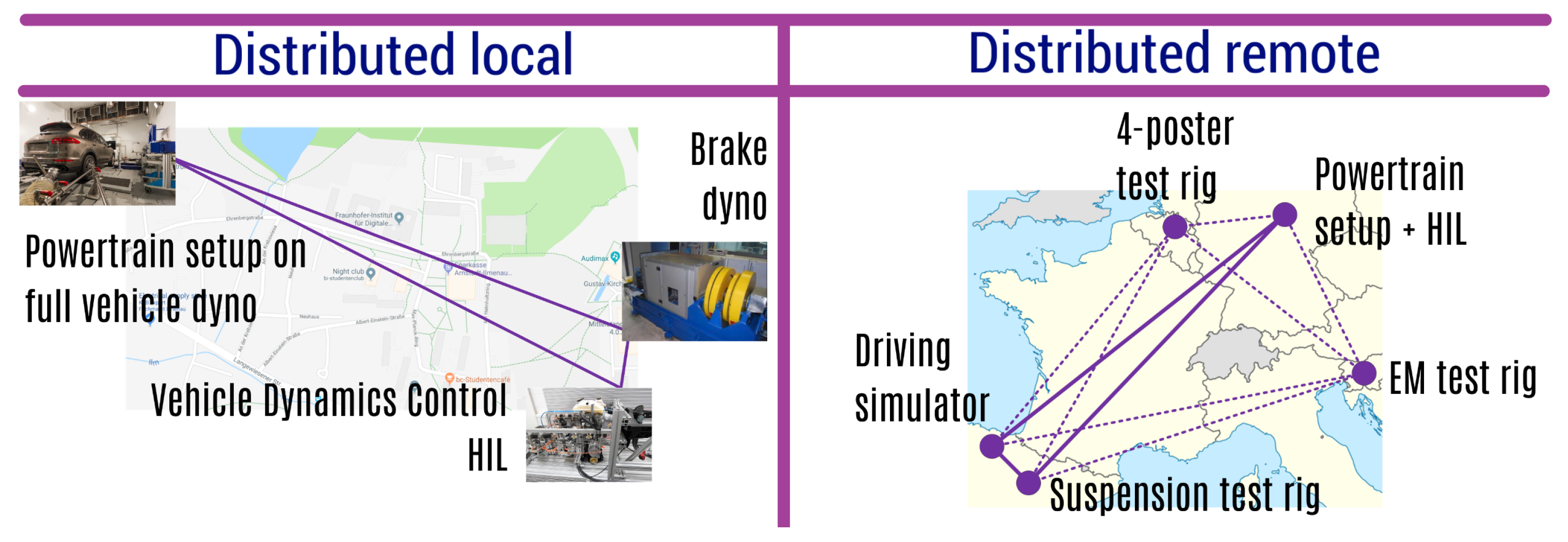
There are two principal ways to establish the XILforEV framework with connected experimental setups. For a distributed local variant, the setups are distributed within the narrow location, e.g., within the company site, university campus, etc. An example is shown in
Figure 2 (left), where three test setups are connected within the campus of Technische Universität Ilmenau in Germany. In this case, the distance between the test setups can be over 1 km and the local fiber-optic connection can still be used. In a distributed remote case, the setups are distributed remotely between different geographical locations. Here an internet-based connection is required for the establishment of the XILforEV framework. The corresponding example is shown on
Figure 2 (right), where the main test setups are located in Germany (Ilmenau), Spain (Ermua and Zaragoza). The secondary test setup in Slovenia (Ljubljana) and Belgium (Sint-Truiden) can be plugged on-demand.
For the distributed remote case, a shared XIL testing approach using communication through the internet is shown in
Figure 3. Here the full vehicle model will run in a global server located in one site (it could be also a cloud server). In this model the subsystem and controllers will interact as functional mock-up units (FMU) with a co-simulation strategy based on the functional mock-up interface (FMI).
Communication between the full EV model and the different testing sites will rely on the user datagram protocol (UDP). This decision has been taken on the basis of previous investigation of the authors that is reported in [
7]. The following UDP advantages are considered within the XILforEV framework:
Compatibility with widely-used communication hardware based on IP/Ethernet;
A maximum transmission unit size in accordance with the REC768 standard is 1472 bytes that is much higher as compared to other protocols such as CAN or MOST;
For up-to-date ethernet devices and distributed local frameworks, the data transfer rates can be up to 1000 Mbit/s;
A cyclic point-to-point communication time <1 ms is possible and fully acceptable for most EV design tasks;
Under consideration of modern global internet technologies, UDP/IP also provides the addressing and routing services that allow reliable sharing of distributed RT systems.
Despite the listed advantages, UDP-based communication systems require careful tuning for remote and shared test network. To address known weak points in this regard, the XILforEV architecture is embedding such elements as (i) redundant routing, (ii) compensation algorithms to recover the loss of messages, (iii) delay compensation algorithms based on estimation tools, and (iv) prioritization of UDP messages within the testing network.
To provide more robustness the XILforEV approach proposes the use of virtual local area networks (VLANs) for local distributed XIL, and virtual private networks (VPNs) for remote distributed XIL. VLAN allows the separation of physical connected devices and networks without interactions or collisions. Furthermore, a prioritisation of traffic can be done to optimise the data exchange according the real-time requirements of each datagram and to reduce the full utilization. Experiments on the campus of TU Ilmenau represent a local connected XIL. Therefore real-time systems exchanged UDP messages over virtual LANs using an executing time of 1 ms. The results in
Figure 4 confirm a low round-trip time of 2 ms. This corresponds to a sending or receiving time less then 1 ms from point to point. The narrow mode of the probability density function (pdf) indicates a robust and deterministic communication.
VPN extends the VLAN to a public network and allows staying in the private network by using public networks. This technology enables users to send and receive data in a safe way through a public network, using their private network address. Another experiment was conducted with real-time systems located in Ilmenau (Germany) and Tokyo (Japan) to investigate the round-trip time of remote routes, exemplary. As shown in
Figure 5, remote routes introduce a significantly higher round-trip time. For instance, the round-trip time (RTT) between Ilmenau and Japan is about 180 ms. Such high RTTs require additional methods for compensating the delay introduced by remote routes. Such methods are not part of this paper; however, they will be presented in future works. The width of the mode indicates a higher jitter in comparison with local distributed systems. However, the pdf value is similar to the normal distribution and indicates a robust connection as well.
It should be emphasized that the data presented on
Figure 4 and
Figure 5 were obtained from the test procedures organized as follows: (i) each singular measurement has been performed over 10 min; (ii) six singular measurements were done daily; (iii) the whole daily programme has been repeated every day over a week. With such an approach, the time-dependent variations in the network load have been fully considered.
All the presented experiments used VLAN and VPN protocols at the hardware level. This reduces additional introduction of delays compared with software solutions. This was confirmed by previous studies of the authors [
7]. Beyond this, the VLAN and VPN used connection-oriented TCP for transporting the messages. As was demonstrated, the combination of UDP over VLAN/VPN offers the advantages of both protocols: low overhead/effort and robust connection.
3. Modelling Components
EV design requires complex simulation works on various product development stages, therefore, relevant modelling topics are also integrated in the XILforEV concept. It relates in particular to MIL/SIL components and to RT models of HIL components. In MIL and SIL environments, there is no defined time line for the model simulation. Therefore, when dealing with complex products involving different domains and different physics, the engineer can decide the best trade-off between the required accuracy and the computational cost. A usual approach consists of starting with high spatial resolution methods like FEM or CFD. and later integrating the results in a lumped parameter model. This lumped model should properly represent the dynamic system (plant) evaluated with a time step that is the base for the controller development on the next design stage. However, the characteristic time of standard simulation strategies is usually not compatible with the real-time constraints compulsory for HIL testing. These complex models or full order models (FOMs) do not allow proceeding in real-time. Model order reduction (MOR) techniques allow obtaining simple real-time models. However, the higher the accuracy of the ROM with respect to the original model, the higher the effort needed to build the ROM. Furthermore, to the uncertainty and lack of fidelity of the initial simulation model, it is necessary to consider an additional reduction in the accuracy that further deteriorates the confidence of the corresponding models.
To address the mentioned problems, the XILforEV approach proposes the use of high-confidence models, which are relevant to the EV development process, on the basis of two concepts: dynamic data driven application systems (DDDAS) [
9] and multi-fidelity models (MFMs) [
10]. The integration of both concepts into the XIL architecture is given on
Figure 6. With this approach, industrial users can have models based on their CAE tools with required accuracy according to their product knowledge (FOMs or HFMs). These models have to be downsized to the real-time requirements established by HIL testing in the shape of low-fidelity models. On the other hand, different testing facilities are then ready to test the EV subsystems in realistic conditions. By using an application lifecycle management (ALM) platform holding the original requirements and test cases, the users can control the test parameters and trigger the different test benches. Through a bidirectional connection between the test benches and the ALM platform, reliable data from the sensors in the test benches can be pushed back. This way, results are traced back to their originating test case and the user has reliable information on the overall testing status. This established traceability from requirement over test case to test results enables the automatic generation of the necessary reports.
The proposed interconnection of DDDAS and MFM procedures can be illustrated with
Figure 7 and involves the following components:
Initial system/component model: a reduced order model (ROM) of the product is able to run in real time or accelerated time, but is not necessarily extremely accurate, in order to facilitate its development in a short period of time with little effort if needed. This can be developed offline ad-hoc for the system in question, but always follows a similar strategy;
Data assimilation layer: a data processing module for the gathering of input/output data from the test bench and a layer of data processing to generate a data-driven correction model;
Plug-in module: a module for connecting the data-based correction back into the model to improve its accuracy. This will constitute an additional term of the ROM that is continuously evolving to adapt the accuracy of the model.
The proposed DDDAS includes also the machine-learning layer for deriving ROM with online decision-making and the use of the test bench data,
Figure 8. The model will automatically increase the confidence level without increasing the development time and preserving the real-time constrains for the HIL testing. This model improvement loop can be done on-line with an immediate use of the new model predictions. To improve the model stability, the automatic updating could be down-sampled based on tracking an indicator of the model variation. The dynamic data-driven ROM is being obtained with an analogue approach to the one used and described in the projection of the initial model. Hence, the compatibility with the rest of the subsystem models is ensured.
The implementation of described concepts within the XILforEV framework is carried out in two steps. First, it is developed and set up in one of the XIL test sites and for one of the subsystems. Once it is ready, the solution is being adapted to the rest of the subsystems and XIL sites. The case studies, where these concepts are being implemented, are introduced in next section.
4. Use Cases
XILforEV use cases are selected to show the potential benefits of the shared XIL strategy in terms of development of complex functions involving different subsystems and the incorporation of fail-safe studies in such a context. Four use cases under discussion are designed for an all-wheel drive sport utility vehicle with four individual in-wheel motors (IWM) dedicated to (i) brake blending, (ii) ride blending, (iii) integrated chassis control, and (iv) fail-safe and robustness studies. Their features are summarized in
Table 1.
Brake blending is a relevant issue for electric vehicles since they are using two types of deceleration devices, namely the friction brake and the electric motor/generator. In terms of the interaction of the friction brake and electric generator, one of the most important objectives is to ensure that the driver does not recognize the transfer phase between these two devices (in terms of body movements and acoustics as well). Moreover, the deceleration should be aligned with energy efficiency targets (highest possible amount of electric recharging) and safety targets (maximum stopping power and minimum stopping distance respectively). To investigate the brake blending, the XILforEV architecture as shown on
Figure 9 is proposed. Test scenarios include: service braking; emergency braking; and brake blending with ABS intervention. The main design task: brake blending controller optimized by criteria of braking performance, energy efficiency, and driver comfort.
Ride blending is a new technology for electric vehicles assuming joint control on the vertical motion dynamics of the vehicle both through individual electric motors and active suspension. This technology, initially developed on a conceptual level in cooperation between DRiV and TU Ilmenau [
11], is assumed for coming generations of EVs. The challenge—especially taking into account electric SUVs as a target vehicle—is to achieve optimal ride quality on roads with considerable roughness and unevenness. The corresponding XILforEV architecture is shown in
Figure 10. Test scenarios include: routine manoeuvers on roads with different surfaces and handling manoeuvers on roads with different surfaces. The main design task: ride blending controller optimized by criteria of driver comfort and driving safety.
The combination of active chassis systems from the first and second use cases leads to next use case for the integrated chassis control design, represented by the brake blending and ride blending. This integration can bring an essential effect in simultaneous improvement of the driving safety and comfort of EVs, especially in the case of critical manoeuvres. A corresponding variant of the XILforEV architecture is shown on
Figure 11. Test scenarios include: stability and handling manoeuvers on roads with different surfaces. The main design task: EV integrated chassis controller optimized by criteria of driving safety and comfort.
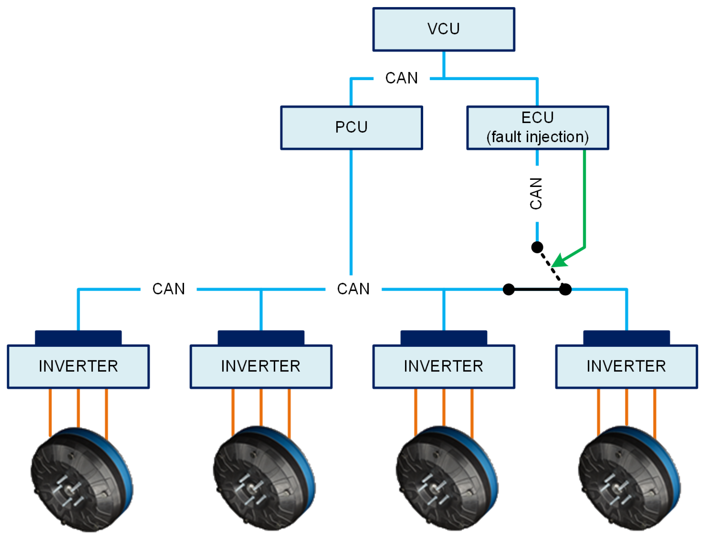
The final use case is a demonstration of the XILforEV technology potential for fail-safe and robustness studies. The scenario selected will replicate an error in the motor operation in one testing site and its implication on the full vehicle behavior will be analysed in the shared XIL,
Figure 12. For the purpose of simulating the fault injection, an additional engine control unit (ECU) will be added to the powertrain architecture model, which is able to take control over the one “faulty” propulsion unit (faulty inverter or motor) in case of need. Different fault scenarios are then implemented on the ECU and can be modelled, for instance, (i) Communication lost (no torque from propulsion unit); (ii) Motor short circuit test (motor braking torque); (iii) Opposite motor torque. Actual speed and torque value of “faulty” propulsion units is sent to the vehicle control unit. The vehicle control unit (VCU) takes these values and torque/speed values from other propulsion unit sent by the propulsion control unit (PCU). Based on all torque/speed data, vehicle longitudinal and lateral response is calculated. With the driver in the loop, it is possible to define controllability of the tested scenarios. The main design task: electric powertrain fail-safe control strategy.
5. Conclusions
The introduced architecture of remote and shared experiments, corresponding modelling components and relevant use cases are addressing a new development and testing technology for EVs and EV systems, through an integrated approach combining different experimental environments, well beyond established XIL procedures in the automotive industry. In fact, the cost and time efficient design of new innovative EV systems depend on several concurrent factors can be effectively optimized through the networking and sharing of experimental procedures. The XILforEV approach is also enabling several technological and business cases that can be summarised as follows:
Shared experimental environments—a service for connected complex test setups and hardware/virtual labs that can be used for specific engineering tasks, which are to be investigated using traditional SIL/MIL/HIL procedures and real-world tests on full-scale demonstrators;
Real-time simulation clouds with open plug-in interfaces for connected hardware setups—an extension of available simulation cloud business models towards real-time domains for designing and validation of physical systems;
Beyond the automotive industry, this technology could be also applicable to other transportation domains, like aerospace (future distributed propulsion aircrafts), rail or marine.

 ,
, 


