
Abstract
Textile electronics have become an indispensable part of wearable applications because of their large flexibility, light-weight, comfort and electronic functionality upon the merge of textiles and microelectronics. As a result, the fabrication of functional fibrous materials and the integration of textile electronic devices have attracted increasing interest in the wearable electronic community. Challenges are encountered in the development of textile electronics in a way that is electrically reliable and durable, without compromising on the deformability and comfort of a garment, including processing multiple materials with great mismatches in mechanical, thermal, and electrical properties and assembling various structures with the disparity in dimensional scales and surface roughness. Equal challenges lie in high-quality and cost-effective processes facilitated by high-level digital technology enabled design and manufacturing methods. This work reviews the manufacturing of textile-shaped electronics via the processing of functional fibrous materials from the perspective of hierarchical architectures, and discusses the heterogeneous integration of microelectronics into normal textiles upon the fabric circuit board and adapted electrical connections, broadly covering both conventional and advanced textile electronic production processes. We summarize the applications and obstacles of textile electronics explored so far in sensors, actuators, thermal management, energy fields, and displays. Finally, the main conclusions and outlook are provided while the remaining challenges of the fabrication and application of textile electronics are emphasized.
Highlights
Major pathways of textile electronics research are introduced, including manufacturing of textile-structured electronics and heterogeneous integration of microelectronics and textiles.
The fundamental principles, representative varieties, and challenges and opportunities of each manufacturing or integration technology are elaborated.
Recent advancements and urgent challenges in wearable textile electronics are surveyed.
Essential tasks and future research directions for wearable microelectronic textile systems are discussed.
Export citation and abstract BibTeX RIS

Original content from this work may be used under the terms of the Creative Commons Attribution 4.0 license. Any further distribution of this work must maintain attribution to the author(s) and the title of the work, journal citation and DOI.
1. Introduction
Textile electronics, an emerging interdisciplinary branch of textile engineering and microelectronics that allows the emission, conduction, and operation of electrons in fibrous substrates, are concerned with fibers or fiber assemblies that can interact with surroundings via stimuli sensations, actuation delivery, thermal management, energy harvesting and storage, decision making, display, communication, and calculation [1–7]. Electronic components found in normal electronic design are available in a textile electronic version. These include sensors [8, 9], actuators [10, 11], heaters [12, 13], coolers [14, 15], generators [16, 17], solar cells [18, 19], light emitting diodes (LEDs) [20, 21], microfluidic devices [22], and microelectromechanical systems (MEMS) [23]. As textile technologies and electronic engineering merge, conventional textiles and electronics are bridged by taking full advantage of textile characteristics without sacrificing the performance of integrated electronics, allowing the combination of their positive features to flourish. The advantages of textile electronics systems, including high wearing comfort from flexibility and breathability as well as excellent usage lifetime from durability and washability, have inspired numerous applications in the fields of wearable electronics [24, 25], soft robotics [26], and extended reality [4]. The fabrication of textile electronics has attracted increasing attention, and can be categorized into two major routes: the processing of functional materials into textile-structured electronic devices with connections as a system; and the heterogeneous integration of commercial microelectronics into normal textiles.
During the initial growth stage of textile electronics, textiles were considered as passive platforms for bulky electronic components to be attached to, inevitably sacrificing their flexibility and wearable comfort. A number of advances immediately emerged due to the miniaturization of electronic components and the increasing complexity and functionality of light-weight electronics, which opened up a wide range of possibilities for textile electronics through the integration of electronics with clothing [27]. Systems based on such concepts produces new requirements. In addition to dealing with the trade-off between reliability and flexibility when connecting materials with modulus mismatches, the package must also be conformable, or even washable. These needs of integration of textile electronics have driven the innovation and adaption of electronic joining and packaging technologies such as mechanical gripping [28], soldering [29], and conductive adhesives [30]; textile decorative techniques such as applique and embroidery [31]; and conductive path printing such as ink-jet printing [32] and screen printing [33]. With new construction and integration methods derived from material processing engineering and textile technologies, textiles and electronics are seamlessly integrated with improved performance and quality.
Fabrication of textile-shaped electronic devices has been realized by industrial textile processes at many stages, including fiber, yarn, and fabric production. Fibers or yarns with electrical functionalities can be continually produced via melt-spinning [34], wet-spinning [35], electrospinning [36, 37], and coating [38, 39]; among them, the electrically conductive fibers and yarns are essential building blocks for textile electronics. Pronounced conductive materials have been studied in this regard, including metal nanoparticles and nanowires [40, 41], carbon nanotubes (CNTs) [9, 42], graphene [43, 44], two-dimensional (2D) transition metal carbides and nitrides (MXenes) [8, 45], conductive polymers [46], and polymer composites [47]. The selection of the conductive material plays the key role in realizing high electrical conductivity, stretchability, flexibility, and stability of fibrous materials as electrodes, conductors, and sensors [48, 49]. Along with the material expansion, the development of processing methods for completing active materials [20], embedding tiny electronics [50], and coating encapsulation layers [51] on or in thin and flexible fibers under mild conditions has led to the widespread exploration of soft and deformable fiber-shaped electronic devices. Electronic fibers or yarns can then be effectively constructed into fabrics using conventional textile techniques, such as weaving, knitting, braiding, and nonwoven; and directly inserted into fabric structures via sewing and embroidery.
There is a general need to scale up the production of textile electronics with high performance in both electronic functionalities and textile quality; this research is multidisciplinary in nature and involves textile technology, polymer processing, electronic engineering, nanotechnology, material science, etc. In this way, an understanding of conventional and advanced textile electronic production processes will lay the groundwork for textile electronics innovation. In this review, we have compiled and categorized current findings to provide comprehensive coverage of textile electronic manufacturing technologies and exploration work. With regard to textile hierarchical structures, we summarize the fabrication of textile structures, starting at the fiber level and moving through yarns to fabrics, along with examining the structure and properties of the fibrous materials resulting from the selection and manufacturing of materials. Then, various devices based on textile electronics are presented with related mechanisms, structures, and performances to provide a global view of the development and applications. In this discussion, we build a framework for guiding the construction of textile electronics and systems and providing a broader and deeper understanding to meet the needs of next-generation wearable electronics.
2. Manufacturing of textile-structured electronics
Electronic textiles can be presented in forms of fiber, yarn, or fabric, as illustrated in figure 1. Textile electronics research directions can be summarized into two main pathways. The first way is the development of new textile electronic devices by building nano- or submicron structures inside or on the surface of textiles where the functional materials are used. The second approach is the integration of microelectronic or MEMS devices into fibers, yarns or fabrics as hybrid electronics [4]. The following section introduces fabrication technologies of the first approach.

Figure 1. Overview of the development of textile electronics. Electronics are chronologically and continuously integrated and embedded into textile structures among fabrics, yarns, and fibers. The functionalities of textile electronics cover sensing, actuation, display, heating/cooling, and energy harvesting and storage.
Download figure:
Standard image High-resolution image2.1. Electronic fibers and yarns
Most fiber electronics have been made from synthetic polymers and functional materials because of their high thermo/electro-stability. Various routes of fabrication have been adapted from industrial textile processes including melt-spinning, wet-spinning, electrospinning, two-step thermal drawing, and yarn fabrication for large-scale production. Direct fiber printing, on the other hand, show its advances in fine structure control of electronic fibers. Post-process such as coating and texturing are widely applied to endorse conventional insulated fibrous materials with electronic functionalities.
2.1.1. Melt-spinning.
Melt-spinning is one of the most common technologies to produce thermoplastic synthetic fibers and filaments, such as polyester, nylon, and polypropylene (PP). In the production, polymer pellets or granules are firstly fed into the screw extruder with progressively controlled heating zones. Functional fillers are also added and uniformly mixed with molten polymers at this step; the shear gradient across the undispersed fillers provided by the extruder as well as the wetting effect on individual filler surfaces by melting polymers work synergistically to obtain a homogeneous mixture. The molten then pumps through the spinneret to form filaments with specialized shapes, followed by solidification in the quenching chamber or water bath. The melt-spinning system is also equipped with an additional mechanical drawing system to stretch the as-spun filament to several times the original length, which can enhance the molecular orientation and strength of the fiber. The common approach of melt-spinning for textile electronics is compounding thermally stable and processable functional materials, such as conductive materials [52], antibacterial materials [53], and dielectric materials [54], with melt-spun polymers. Scholars have conducted many studies to fabricate conductive melt-spun fibers. The addition can be graphene [55], carbon black (CB) [56], CNTs [57] and polyaniline (PANI) [58]. However, the tenacity of these conductive fibers is relatively lower than conventional melt-spun fiber mainly due to the insufficient internal stress transfer at the interface of polymer matrix and fillers. The addition also increases polymer viscosity causing blockage and fluctuations in processing, quality, and variety [59]. Besides adding functional materials, melt-spinning also can spin filaments with specialized cross-sectional shapes. An example is the piezoelectric core-sheath fiber made by feeding polyvinylidene fluoride (PVDF) as the sheath and 10 wt% CB/polyethylene as the core into the multichannel spinneret separately, which was further drawn into the microfiber for energy harvesting, as shown in figure 2(a) [60]. Moreover, multiple functional materials can be blended and/or synthesized with the melt-spun polymer to spin composite fibers as electronic devices, for instance, a piezoelectric textile harvester was made from barium titanate nanoparticles, PVDF, and reduced graphene oxide (rGO) [61].
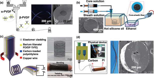
Figure 2. Yarn electronics of different spinning techniques. (a) Melt spinning core-shell microfiber with a conductive core for energy harvesting. Reproduced from [60], with permission from Springer Nature. (b) Schematic illustration of the wet spinning production and structure of core-sheath fiber as a strain sensor, with the cross-section scheme of the fiber. Reprinted with permission from [62]. Copyright (2018) American Chemical Society. (c) Schematic fabrication and structure of the thermal drawing of acoustic fiber with PVDF-TrFE/BTO and photographs of the fiber under bending and twisting. Reproduced from [50], with permission from Springer Nature. (d) Schematic illustration of the direct ink writing and structure of 3D printed fiber (left). An optical image and SEM of the printed conductive fiber cross-section. [63] John Wiley & Sons. © 2019 WILEY-VCH Verlag GmbH & Co. KGaA, Weinheim.
Download figure:
Standard image High-resolution image2.1.2. Wet-spinning.
Wet-spinning is normally used for the materials that can be dissolved in a suitable solvent, such as cellulose, acrylic, aramid, and conductive polymers. During the spinning process, the polymer firstly dissolves in a suitable solvent, then the dissolved polymer is pumped through the spinneret, and finally is transferred to a coagulation bath for consolidation. The key process of wet-spinning is the solidification in the coagulation bath, during which the diffusion interchange occurs between solvent and coagulant. It starts at the boundary of the polymer solution forming a sheath/core structure and slowly moves inward to the center of the fiber subsequently. Many researchers have investigated this diffusion process in the coagulation and have developed models for the wet-spinning process [64, 65]. From their studies, polymer solubility, spinning pressure, and coagulation bath under the influence of solvent composition and proportion as well as temperature are crucial elements to the solidification speed, void formation, and other as-spun fiber properties [66]. Moreover, the diffusion rate differs between different solvents and coagulants.
Using the wet-spinning method, a number of conductive fibers were demonstrated, such as the fibers made from poly(3,4-thylenedioxy-thiophene):Poly(styrenesulfonate) (PEDOT:PSS) with a conductivity of 223 S cm−1 [67], meter-long MXene fiber with electrical conductivity as high as 7 713 S cm−1 via wet-spinning [68] and graphene fibers [69]. Wet-spinning was explored to produce hybrid fibers composed of multiple materials. For instance, fibers containing graphene oxide and vanadium pentoxide for fiber batteries cathode are demonstrated in figure 2(b) [70]. This cathode can sustain 500 bending cycles, displaying better reliability than surface-coated fibers. Another example is a sheath-core stretchable conductive fiber with polyurethane (PU) as the sheath and GaInSn as the core [71]. Apart from conductive fibers, wet-spinning also can be used to directly fabricate other electronic devices, such as a fiber-based strain sensor, comprised of a CNT-elastomer core for strain sensing and a pure elastomer sheath for encapsulation via the wet-spinning [62].
2.1.3. Electrospinning.
Electrospinning has been applied to make fine fibers, yarns, and fiber webs from both molten and soluble polymers. Compared with melt-spinning and wet-spinning, it can only integrate a small amount of functional material into polymers, and like both of them, intrinsic conductive materials can also be processed via electrospinning. In the electrospinning, the polymer solution or melt is injected out as a charged droplet by the electric field. The droplet deforms from a broadly spherical shape to an elongated cone shape termed as Taylor cone. In this way, both conductive polymer composites and intrinsically conducting polymers can be processed into conductive fibrous web and porous membrane via either melt-electrospinning or solution electrospinning [72, 73]. Polymer solutions, electrospinning operation parameters, and environmental factors, such as relative humidity and temperature, are crucial in controlling the morphological properties of electrospun fibers [74, 75]. Polymer solubility, solvent concentration, solution viscosity, and solution surface tension may interact with each other to control the polymer crystallinity and morphology of fiber [74]. For example, to avoid the formation of beads and electrospraying, solution viscosity needs to be maintained over a threshold, which is related to solvent evaporation and polymer solubility. Operational factors cover the applied voltage, feed rate, distance between spinneret and collector, and types of collectors. These factors may interact to adapt fiber flight time and productivity. The priority is that the applied voltage needs to overcome a threshold of the surface tension of Taylor cone to initiate electrospinnning [76].
2.1.4. Two-step thermal drawing.
Two-step thermal drawing is a method for fiber optics initially and has been explored for fiber electronics with multiple materials or even embedded microelectronic chips. A preform is prepared as an enlarged precursor of the fiber. It may be composed of multiple materials or components in varied shapes, through different machining procedures, such as milling, lathing, or laser cutting [77]. Then the preform is held in a hot furnace of a drawing tower over a period of time for softening. The temperature needs to be 50 °C–100 °C higher than the materials' glass transition temperature. Next, the softened preform is pulled to form a continuous fiber. Fibers with unique textures or structures have been demonstrated by the controlling of material flow continuity. The matching of material properties is critical, for instance, the glass transition temperatures of the multiple materials should be in the same range and viscosities [78]. A piezoelectric composite fiber was reported, which was made up of P(VDF-TrFE)/BTO sandwiched between electrodes with SEBS protection. Enlarged by a fabric structure, the fiber can convert mechanical vibration to an electrical signal [50]. SEBS polymer has been used to make electronic and photonic fibers with 500% elastic deformation [79] and conductive fiber with PVA core wrapping by SEBS film [80].
2.1.5. Fiber printing.
Fiber printing is an additive manufacturing technique that are computer controlled to squeeze materials out of the nozzle, followed by the material curing process, to form filament structures. Among filament-based extrusion, direct ink writing (DIW) is advantageous to print complicated structures with programmed gaps because its solidification involves the rheological transition from pseudoplastic to a dilatant state or the gelation of the paste [81–83]. DIW shows promise in processing multiple materials into fiber electronics. For instance, A core-shell polyimide fiber filled with carbon paste as conductive fiber was made by DIW (figure 2(d)) [63]. When processing one functional ink by DIW. The ink viscosity, mostly characterizing with shear thinning behavior, plays a crucial role in the smoothness of flow out of the nozzle [83, 84]. In order to confirm the stable formation of as printed structures without unwanted structure deformation initiated by the gravity, the ink storage modulus need to be higher than its loss module [81, 83, 85]. To relieve above two conditions, hybrid ink plateau modules and shield yield stress need to be controlled via the addition of rheological modifiers [11]. Another concern is material incompatibility. Since some materials require an additional sintering process, in which the temperature rise may cause damage to the original printing polymer. In addition to material problem, the mechanical strength of printed product is relatively lower than other fiber spinning method, like melt spinning, due to the elimination of drawing process [81].
2.1.6. Yarn fabrication.
Yarns are the assembly of parallel bundles of fibers with or without twists to confer strength, coherence, and other properties. They are available in a variety of yarn counts, structures, and textures to meet specific end uses. The two most common types of yarns are staple spun yarns (fiber length < 60 mm) and continuous filament yarns [86]. Making yarns from intrinsic conductive fibers/filaments, such as copper wires, silver yarns, and graphene fibers, have been used as a basic component for yarn electronics [87]. Conductive yarns were made by assembling CNTs onto the cotton sliver, then followed by ring-spinning [88] or by wrapping stainless steel wires and bamboo charcoal roving for electromagnetic shielding [89].
Hollow-spindle spinning is a more frequently used method to wrap conductive materials or one-dimensional (1D) electronic circuit assemblies with textile fibers. By using a lab-made machine to encapsulate 1D flexible circuit board assembly with conventional yarns as a novel electronic yarn [90]. It can be applied to different textile products, such as bracelet and clothing. Yarn-based triboelectric nanogenerator (TENG) has been demonstrated by using this method with polyimide yarn and conductive yarn. The yarn device can then be woven as fabric [91].
2.1.7. Coating.
Besides the development of intrinsic electronic fibers and yarns, coating insulated fibers and yarns with conductive materials is one of the facile ways to obtain conductive fibrous materials. Typically, the coating techniques can be divided into physical coating methods and chemical coating methods [92]. Physical coating methods include dip-coating [93], spray-coating [94], blade-coating [18], and electrophoretic deposition [95], while chemical coating methods include chemical vapor deposition (CVD) [88], atomic layer deposition (ALD) [96], etc. Similar to the dyeing method of commercial textile processing, dip-coating is a process the outcome of which is the application of a thin film of desired materials to the substrate surface; it can effectively cover textile materials with solution dispersible or soluble functional materials such as carbon nanomaterials [97], conductive polymers [98], and metal nanomaterials [99] in mild conditions. For example, Lee et al dip-coated PEDOT:PSS and single-walled carbon nanotubes (SWCNTs) onto to PU fibers with oxygen plasma treatment [100]. The strong interaction between PU substrate and conductive sheath enabled by hydrogen bonding guarantees the formation of uniform microscale wavy architectures upon releasing the pre-stretched fiber. Thus, the fabricated sensors demonstrated high thermal sensitivity without interference from tensile strain below 180% in a reversible manner.
Despite the facile and scalable advantages, the typical textile coating methods nowadays still suffer from low resistance to washing and are not satisfactory for high-resolution pattern coating [101]. CVD, as a non-line-of-sight vapor-based deposition method widely used in microelectronics, show the potential for overcoming these challenges [102–104]. In the CVD process, covalent bonds are formed on the interface of the resulting hybrid material and the textile surface, which improves the mechanical durability [105]. For example, PP fiber-based temperature sensors with a uniform layer of graphene grown by CVD showed no significant change in the resistance after multiple washing and bending tests [106]. The thickness of coating layer generated by CVD is limited by the slow penetration of reactive vapors into the textile structure. ALD, a variation on CVD, where the reaction occurs on the surface through sequentially exposure and purge two or more gaseous precursors, allows the growth of films on a substrate with extreme thickness control [107]. For instance, by utilizing ALD pretreatment to induce hydroxy double salt nanosheets on carbon fibers, Zhao et al proposed a functional smart fiber composite for an ultra-sensitive flexible glucose sensor [108]. In addition to good sensitivity and fast response, the prepared glucose sensors exhibited good flexibility and stable electrochemical performance under 100 cycles bending at 180 °C.
2.1.8. Texturing.
Texturing is a treatment in which flat filaments are distorted to have loops, coils, buckling, or crimps along their length to gain high bulkiness, porosity, softness, and elasticity. A typical texturing process for a filament yarn begins with a yarn distorting process like twisting that improves the crystallinity and orientation degree of fibers, followed by heating to weaken the van der Waals forces and hydrogen bonding between polymer chains and to keep the filaments crimped. After that, the distorted yarn is cooled down and enabled with new interaction between polymer chains [109]. Based on the high orientation degree of both polymer chains and crystals along the filament, Baughman et al wrapped highly twisted yarns around a mandrel and then stabilized the coiled fibers by thermal annealing to fabricate thermal-induced contraction artificial muscles with 4% strain contraction. Buckling textures with the ability to absorb large strains through flatting the wave structure are widely used in making stretchable conductive fibers which are basically fabricated by releasing pre-stretched elastic fibers coated with conductive materials as sheath [110]. Among the texture-related properties of textiles, the friction of the fibrous material surface is the main characteristic that significantly affects the output power of TENG textiles. For example, Huang et al tuned the micro-morphology of knitted textiles in a wide roughness range, and found that the resulting TENG textiles with face loops and higher stitch densities proved to be the optimum structural design for output power performance [111].
2.1.9. Challenges and opportunities of electronic fibers and yarns.
Despite progress in spinning electronic fibers and yarns, challenges remain in terms of comfort, large-scale production, and commercialization. While miniaturization has made these materials more flexible and comfortable, their mechanical performance is not yet sufficient for integration and use. Additional texturing and structuring techniques are needed to explore their comfort further.
Although low-cost spinning techniques can be scaled up, they are only suitable for a limited range of functional materials possessing unignorable risk potential for equipment and environment. Advanced manufacturing processes for fine structure fabrication inject new vitality in the field but are still expensive and not fully mature. These limitations result in a lack of diversity and functionalities of fiber/yarn electronics, which hinder the construction of electronic fabrics and the integration of textile electronics. Standardization and quantification of fiber/yarn electronics are urgently needed to confirm their quality and safety and promote large-scale production and exploration of the market for these innovative products.
2.2. Electronic fabrics
Fabrics are normally 2D assemblies of fibers, yarns, or textile strips with a substantial surface area in relation to their thickness. It is flexible, porous, soft, and strong because of the discontinuous inter-fiber movement controlled from fabric structure. Fabrics can be divided into yarn-based fabrics made up of yarns and fiber-direct fabrics made up of fibers [112]. The yarn-based fabric techniques include weaving, knitting, and braiding, while the fiber-direct fabric technique is non-woven fabrication.
2.2.1. Weaving.
Weaving interlaces two sets of yarns as weft and warp at the right angle to fabricate woven fabrics (figure 3(a)) [31]. In the woven structure, the warp and weft yarn contact each other at the cross-over points. It is applicable to produce patterns with varied numbers of weft and warp to achieve desired properties, such as porosity, strength, in-plane shear and extensibility. Weaving is a common method for fabricating textile electronics and integrating textile electronics into fabrics because of the small deformation in the weaving process and in the woven structures. The weft yarn has lower requirements on the yarn strength, elasticity, and mechanical properties. In figure 3(b), 200 µm wide commercial polyimide circuit strip was used as the weft yarn with sensing and display function [113]. In this study, the maximum strain of the yarn in plain weave is around 2.2%, which is considerably lower than that of the circuit damage threshold (10%). Moreover, the interaction between weft and warp yarns provides a potential platform to connect different devices to realize various functions as a textile electronic system. Weaving technique was utilized to integrate different electronic components, including pressure sensors, strain sensors, circuit boards, logical operation, solar cells, and batteries, as a system of medical monitoring (figure 3(c)) [114].
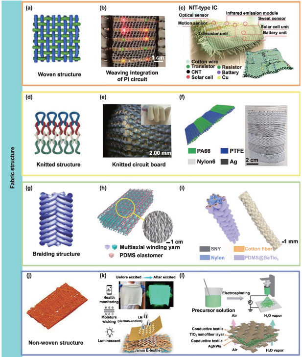
Figure 3. Fabric electronics of woven, knitted, braiding, and non-woven structures. (a) Woven structure. [31] John Wiley & Sons. © 2018 WILEY-VCH Verlag GmbH & Co. KGaA, Weinheim. (b) Integration of the polyimide circuit into woven fabric. © [2010] IEEE. Reprinted, with permission, from [113]. (c) Schematic illustration of the fabric-based medical monitoring system and corresponding photograph. The battery in the system is 2.5 cm × 5.2 cm in size. Reproduced from [114], with permission from Springer Nature. (d) Knitted structure. Reproduced from [116]. CC BY 4.0. (e) Photographs of a knitted circuit board. Reproduced with permission from [117]. (f) Schematic structure and photograph of the tubular knitted triboelectric harvester. Reprinted from [118], Copyright (2020), with permission from Elsevier. (g) Braiding structure. Reprinted from [119], Copyright (2015), with permission from Elsevier. (h) Schematic structure and photograph of the 3D braided triboelectric harvester. Reproduced from [120], with permission from Springer Nature. (i) Schematic structure and photograph of the 2D braided triboelectric harvester. Reprinted from [121], Copyright (2022), with permission from Elsevier. (j) Non-woven structure. (k) Schematic structure and photographs of the non-woven human-machine interface. Reprinted with permission from [122]. Copyright (2022) American Chemical Society. (l) Schematic fabrication and structure of the electrospun capacitive pressure sensor. [123] John Wiley & Sons. © 2020 The Authors. Published by WILEY-VCH Verlag GmbH & Co. KGaA, Weinheim.
Download figure:
Standard image High-resolution imageElectrically conductive woven fabrics have been made from conductive yarns by automated weaving looms and sold in the market for many years. They have been used widely for large-sized applications in electromagnetic field shielding and electrodes for devices. However, for the integration of microelectronic electronic devices, several problems hinder progress. Firstly, the circuit design or device alignment needs to be at the right angle, matching the weft and warp yarn interaction. It is impossible to have an arbitrary or planar curved circuit design in weaving because this may conflict with the mechanism of weaving. On the other hand, right-angle circuit design may also have energy efficiency problems. Another critical point is that the weaving loom has strict requirements on the uniformity of warp yarn linear density [115] and the current microelectronic yarn cannot match this requirement because of the various sizes of the microelectronic chips. Thus, most current electronic fabric requires varied degrees of customizability to production techniques, limiting its yield and commercialization. In addition, the precise control of the weft yarn insertion is a challenge to confine the location of the microelectronic device. In the process, the corresponding shedding may generate a strong squeeze and undulation of yarns in each cycle. The interaction between warp and weft also generates stress to form creep. These may damage the functional material and shorten its lifespan, which might be deteriorated with higher loom speed.
2.2.2. Knitting.
Knitting is the technique of bending yarns into loops (figure 3(d)), which intermesh each other either row-by-row or column-by-column, by using of needles and control devices like sinkers and cams. In the knitting process, the yarns are fed to the needle and bent into the shape of a loop under the help of the sinker and the cam [116]. Knitting machines can be divided into circular knitting machines and flat-bed knitting, which main difference is the product format and gauge [124]. In addition to the difference in knitting beds, knitting can generally be categorized as weft knitting and warp knitting relied on the loop formation directions [124]. The loop formation of weft knitting only involves one yarn move and loops subsequently in the horizontal direction, while loop formation in warp knitting requires hundreds of yarns looping vertically. They differ in elasticity and shrinkage value and direction.
A feature of knitted fabrics is their high stretchability due to the loop structure. Knitting with intrinsic functional yarns or filaments, such as copper wires, silver conductive yarns, and polytetrafluoroethylene (PTFE) yarns, to fabricate textile electronics is beneficial and common. These materials can withstand the stress deformation from the knitting process with limited loss of functionality. Knitted structures with conductive silver coated PA yarns have been used for heating in winter garments or surface electrodes in surface EMG monitoring or electro-stimulation. The knit structure allows a high fabric deformation but yet low fiber strain or stress. For instance, a knit flexible circuit board made from PU-coated copper filament exhibits less than 1% electrical resistance variation under 300% strain (figure 3(e)) [117]. In addition, knitting can fabricate circular structures or tubular structure as bi-layers. This is advantageous to combine multiple materials in contact for device fabrication. A textile TENG was reported with nylon 66 and PTFE composite yarns in a tubular knitted structure, as demonstrated in figure 3(f) [118]. However, weft knitting is more common due to its simple processability. Above three textile electronics are fabricated via weft knitting, while warp knitting application is limited. For instance, a stretchable lithium ion battery electrode with island-bridge structure was prepared by warp knitting [125]. This electrode can withstand 1,000 cycles stretching.
2.2.3. Braiding.
Braiding is a common technique for rope, shoe laces and net-shape composite preforms. It requires at least three yarns linked to the same start point intertwining alternatively at interlacing angles in the range of 20°–75°, following a certain algorithm (figure 3(g)) [119]. The braiding machine is normally composed of multiple carriers and horn gears [126]. Carriers can hold up the bobbin as input and control the yarn tension. Horn gears in disk shape with several cuts can transmit the motion to neighboring horn gears as a carrier movement track to build up a track. When carriers move, the yarn interlaces and constructs the next piece of braid at another braiding point [127]. Braiding has been applied in fabricating TENGs because it can interlace multiple materials to form multilayers, which is consistent with the mechanism of TENGs. Figures 3(h) and (i) shows a braided TENG with high compression resilience, enhanced power output, and pressure sensitivity [120] and a core-spun TENG via coating and braiding [121], respectively. Besides TENGs, braiding also can be used to fabricate other devices. An example is the capacitive strain sensor in braid form made up of capacitive pressure yarn sensors for a miniaturized interface to recognize gestures [128].
2.2.4. Nonwoven.
Nonwovens refer to the assembly of fibers, continuous filaments, or/and chopped yarns as a web, and bonded together (figure 3(j)). Compared to the previous three processes, the nonwoven techniques can directly use fibers or filaments, instead of using yarns [129], endowing the non-woven fabrics with anisotropy, inhomogeneity, porosity, and permeability. Conventional nonwoven procedures involve web formation, bonding, and rolling of goods. The general web formation techniques include dry-laid, melt-spun, and wet-laid [130]. The bonding techniques consist of chemical bonding, mechanical bonding, thermal bonding, and others. The web formation and bonding processes vary depending on the types of materials used. For example, gaseous hydrogen chloride is used to chemically bonded polyamide webs together because polyamide can melt in hydrogen chloride. In addition, web formation and bonding techniques also can be combined in electrospinning and melt-brown processes.
Due to the material requirements, research on the integration and fabrication of textile electronics using the conventional non-woven technique is limited. Figure 3(k) illustrates a nonwoven fiber layer with an additional liquid metal printing the acts as a human-machine interface to control mechanical claw [122]. A conductive nonwoven composite was made from graphene nanoplatelet and polyethylene terephthalate (PET) fiber via the wet-laid method [69]. A capacitive pressure sensor comprising a dielectric layer of the electrospun ceramic non-fibrous network is shown in figure 3(l) [123]. These sensors sustained over 50 000 compressive cycles. Tissue-like mechanical properties and good permeability have been achieved by a hybrid skin conformable electronics based on an electrospinning nanofibrous substrate [131].
2.2.5. Challenges and opportunities of electronic fabrics.
Fabric techniques play a crucial role in the manufacturing process of integrating fibers or yarns to provide coherence and mechanical strength to the deformation during usage. The integration of different fiber and yarn electronic components into a piece of fabric has the potential to the development of an electronic fabric system. However, there are currently limited examples due to several challenges.
One major issue is the significant variation in size, electrical performance, and format of textile electronics components, as they are fabricated using various techniques and materials. Although customized fabric techniques can address this problem, the associated costs increase accordingly. Furthermore, the resulting electronic fabric system may not meet practical standards in terms of aesthetics and comfort due to differences between the fibrous electronics. Another challenge is the need for additional connections between textile electronics components in a fabric. Fabric production arranges fibers and yarns in specialized patterns, but building electrical connections is difficult due to material mismatching and form varying. The mechanical strength of fiber or yarn electronics is another significant challenge in electronic fabric production, as it may not withstand mechanical deformation and stress during production. For example, in knitting, the yarn is deformed into a loop, requiring high flexibility of textile electronics devices in electronic knitted fabric. As a result, current electronic fabrics only involve a single or limited number of textile electronics devices, far from achieving a sophisticated electronic fabric system.
3. Heterogeneous integration of microelectronics and textiles
Besides directly producing fibers and fabrics with inherent electronic functions discussed in section 2, conventional textiles can be imparted with electronic functions. Within the category of post-processing, a wide range of functionalization and integration techniques have been developed. The functionalization of textiles is a simple and scalable process that can be implemented both physically and chemically with existing production processes and machinery. Additionally, textile electronics can be developed by integrating microelectronic components into/onto textiles. The integration of textile electronics has benefited from the strength of several industries, including textiles, apparel, and electronics, with some products available on the market.
3.1. Fabric circuits
Fabric circuitry refers to the methods and techniques used to design and fabricate circuits on fabric substrates with computer-integrated manufacturing technologies. It is an essential component of a full integrated textile electronic system, providing wired coupling between microelectronics on a fabric placed at different locations. Fabric circuits can be created during the fabric formation process, such as weaving and knitting conductive yarns [117, 132]; and on finished fabrics through post-processing methods such as embroidering conductive yarns [31], printing conductive inks [133], and ironing on laser-cut conductive fabric patterns [134].
3.1.1. Weaving and knitting.
In this part, we focus on the integration and interconnection of conductive yarns during these two processes to create a fabric electrical circuit. More specifically, the construction of a network consisting of conductive and nonconductive yarns to form particular conductive patterns according to a given fabric design.
In weaving process, the fabric circuits can be developed in single layer structures including plain, twill, satin, and basket weaves with integrated conductive yarns distributed in one or both of the weft and warp directions [31]. In terms of multilayer woven configurations, some conductive yarns can travel among different layers as well as switch between warp and weft yarns; these structures accommodating a high density of conductive yarns are potential for multilayer fabric circuits board [135]. The regular grid arrangement of yarns allows interconnect at the crossing points between conductive yarns to create the track design [136], and also ensures the correct align of integrated microelectronics [137]. After that, the efficient transfer of current between conductive yarns requires electrical connection with low resistance at the crossing points of conductive yarns. This can be done with several methods, including the complex weaving techniques [138], laser ablation [137], resistive welding [135], conductive adhesives [139], and pressure contact [31]. A pioneer work of various electronic circuits made by weaving specialized fibers integrated with electronic components was reported by Bonderover and Wagner [140] Pressure contacts were adopted to ensure flexible connection between these fibers for the fabrication of a woven inverter circuit (figure 4(a)). Pressure contact brought about by axial tension in yarns is not reliable, but it might be preferred in applications where connection flexibility is the main concern. In addition to the connection of crossing points, the formation of predetermined disconnects along a conductive yarn is necessary for current control.
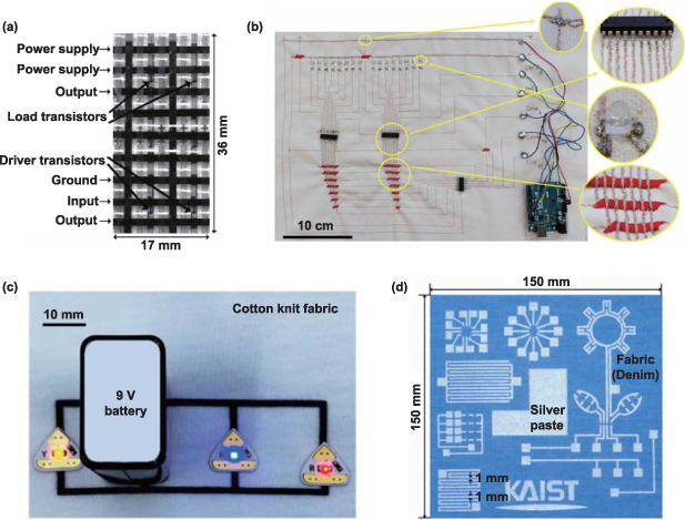
Figure 4. Fabric circuits of different routing techniques. (a) Woven circuit made from active component fibers. © [2004] IEEE. Reprinted, with permission, from [140]. (b) Embroidered circuit linking 16 LEDs with Arduino Uno device and electronic components. © [2020] IEEE. Reprinted, with permission, from [142]. (c) Inkjet printed circuits on the cotton knitted fabric. [143] John Wiley & Sons. © 2020 Wiley-VCH GmbH. (d) Screen printed circuits. © [2009] IEEE. Reprinted, with permission, from [144].
Download figure:
Standard image High-resolution imageKnitted fabrics are distinctive from woven fabrics in their loop structures. Given the knitted structures are relatively easy to be stretched or distorted, high flexibility and stretchability can be accommodated when routing circuits with microelectronics. These distinctive characteristics make knitted fabric circuits suitable for next-to-skin wearable electronics. Compared with weaving circuit in the form of perpendicular wiring and electrical interconnected with post-process, knitted circuit has a higher freedom degree of routing and is timesaving because standard knitted fabrics can be made entirely from a single thread [141]. For instance, a knitted fabric circuit board was reported of being stretched over 300% strain with a current capability of 15 mA [117]. Additionally, the three-dimensional (3D) looped configuration contributed to highly durable, washable, permeable features of electronic fabrics with modulus lower than human skin.
3.1.2. Embroidery.
Embroidery is a type of needlework in which threads or ornamental materials (e.g. beads and sequins) are attached to fabric, generally considered as a technique of decoration [145, 146]. It plays an important role in the construction and integration of electronic components and textiles upon stitch conductive thread patterns that define circuit traces and component connection pads (figure 4(b)). An important step for seamlessly embroidering conductive paths into textiles is to find conductive yarns that are suitable for use with fabrics. Three main considerations of selecting embroidered conductive threads are the electrical conductivity, the process intactness, and mechanical stiffness for wearable comfort purposes. The high conductivity metallic threads are too stiff to be fed in embroidery machine [147]. For instance, highly-twisted plied threads made of several stainless steel yarns performed badly as embroidery threads due to the tension accumulation in filament metal fibers during sewing that caused the threads to bunch up and interrupted the sewing process [148]. While spun steel yarns are more applicable in embroidery machine, the protruding fiber may cause skin irritation to users and undergo unstable electrical connectivity during wearing. Compared with their metallic counterparts, intrinsic conductive polymer yarns and conductive polymer composite yarns dispersed with a low proportion of conductive fillers are more compatible with sewing machine, but the low conductivity might be insufficient to fulfil some textile electronic applications [31]. Thus, metal-plated yarns that provide a higher conductivity and machine-sewability are the most competitive candidate for machine embroidery. Among different types, silver-coated yarns are common embroidery threads used in textile electronics, see table 1.
Table 1. Summary of conductive threads used in machine embroidery.
| Thread | Type | Resistance per unit length | Thread position in embroidery machine | Reference (year) |
|---|---|---|---|---|
| BK 50/2 | Steel and polyester spun fibers | ∼50 Ω cm−1 | Machine-sewable, works as both needle thread and bobbin thread | [148] (2000) |
| BK 12/2 x 275/175 S | Cold-drawn steel filaments | ∼1 Ω cm−1 | Not suitable for needle and bobbin threads, but can be couched with covering stitches | |
| Bekintex 15/2 | 100% stainless steel spun fibers | ∼1 Ω cm−1 | Machine-sewable | |
| VN 140 nyl/35 x 3 | Continuous stainless steel fibers wrapping around a nylon core | ∼10 Ω cm−1 | More suitable to use as bobbin thread, relatively sewable through needle | |
| Shieldex Statex 117/17 twine | Silver-coated polyamide multifilament yarn | 500 Ω m −1 | Both needle and bobbin threads in Semi-professional embroidery machine—Bernina artista 200 | [149] (2006) |
| Shieldtex 117/17-2 ply HCB | Silver-plated polyamide threads | <300 Ω m−1 | Used as needle thread only in ZSK embroidery machine | [147] (2019) |
| Madeira HC40 | silver-plated polyamide threads | <300 Ω m−1 | Used as needle thread only in ZSK embroidery machine | |
| Madeira Germany conductive HC 12 thread 235 × 2 dtex | Silver-coated 2-ply polyester filaments | < 100 Ω m−1 | Used as both upper and lower threads in the MB4 Janome machine | [150] (2021) |
| MADEIRATM HC12 (0.08 mm diameter) | Silver-coated polyamid | < 100 Ω m−1 | Used as needle thread with Brother PR670E Embroidery Machine (304 stitch, cotton thread as bobbin thread) | [151] (2021) |
| Shieldex 235/36 dtex HC | Silver-coated nylon yarn | 100 Ω m−1 | Both needle and bobbin thread in Garudan GF-115-107 LM sewing machine | [152] (2022) |
| X-Silver 410 denier | 100% silver yarn | 110 Ω m−1 | ||
| X-Static 310 denier | 2-ply 99.9% pure silver yarn | 150 Ω m−1 | ||
| ClevertexY05 50 tex | 47% polyester 53% Cu Ag | 6.50 Ω m−1 | Both needle and bobbin | [153] (2022) |
| Clevertex Y08 78tex | 23% PES 77% Cu Ag | 2.85 Ω m−1 | Both needle and bobbin | |
| Shieldex® 117/17 dtex 2-ply conductive thread | 1% nylon polyamide filament 99% pure silver plated | — | Melco® EMT16X industrial embroidery machine, Non-conducting cotton bobbin thread | [154] (2022) |
| Silver-plated conductive thread | Silver-plated conductive thread | — | ZSK JGVA Embroidery Machine | [155] (2022) |
Apart from the intrinsic property of conductive yarns, embroidery parameters also influence the electrical performance of embroidered conductive tracks. The traditional basic embroidery stitches are run, satin, and fill. The run stitches form linear segments, which are employed in creating fine single line conductive tracks and embroidered sensors [147, 149, 150, 155, 156]. A study revealed that silver-plated yarn embroidered tracks made of stitch 301 give the lowest resistance compared with conductive tracks constructed with 101 single-thread chain stitch, 304 zig-zag stitch, and 406 cover stitch [152]. The satin stitches are suitable for creating prominent contour that is wider than run stitched lines, or filling up a small area, showing increased reliability on the layered thick conductive tracks [147]. The fill stitch is running rows of stitches to fill up a larger area as embroider electrodes in some textile electronics [147, 149]. Besides, thread position, stitch density, machine speed, and needle thread pre-tension are factors concerned. It is known that the needle thread under tension is rubbed against metal parts of the machine, including thread guides, take-up lever, tension regulator, and needle eye. Conductive coating can damaged because of the abrasion during embroidery, leading to the resistance increase or even device malfunction. Placing the conductive thread in the bobbin as well as lowering embroidery speed and stitch length can avoid excessive coating abrasion, and therefore, guarantee the conductivity of embroidered tracks [152, 157].
In order to maintain the electrical continuity of embroidered conductive tracks, protective layer on top of tracks are required. Laminating a thermoplastic film via hot-pressing and overstitching high-density zig-zag stitches with insulating threads on the tracks are two major routes, since the polymer layer highly restricts water drying speed which negatively affects the electrical resistance, the latter one displayed better resistance to wash after 50 cycles [147].
3.1.3. Printing.
Printing on fabrics builds flexible conductive traces made up of conductive inks, conductive polymers, or conductive solutions to textiles fixed upon on textile surface at predefined areas [158–161]. Techniques which make these possible include mask-free inkjet printing and rotary printing, that print traces directly by moving the nozzle over and rotating the perforated cylindrical screen on textile substrates, respectively. Printing circuits can also be achieved by covering predetermined masks on fabrics along with techniques such as screen printing, evaporative printing, and sputtering. Generally, conductive printing is suitable for any kind of fabrics such as woven, knitted, and nonwoven structures as long as these methods are non-corrosive and non-destructive to textile materials.
Inkjet printing is the process of appropriate inks to continuously form and deposit small droplets in the size of 100 nm—100 μm onto substrate to generate functional patterns [143]. Such a technique has attracted wide attention for the manufacturing of printed electronics, due to advantages including fully digital mask-less printability, versatile ink formulation, cost-effectiveness, low working temperature, waste-less, and feasibility for scale-up production [32, 162]. To realize stable, repeatable, and high resolution inkjet printing, it is crucial to develop high purity conductive inks in which functional materials are stable and uniformly dispersed without any aggregation [31]. They are categorized into three major groups according to the compositions of metallic solutions, conductive polymer solutions, or nanoparticle dispersed solutions together with the addition of surfactants, dispersants, thickeners, adhesion promoters, or stabilizing agents if necessary [132, 163]. Also, the viscosity and surface energy of inks are critical for the formation and deposition of droplets, respectively. Recently, Uzun et al developed an additive-free, aqueous MXene inks with tunable viscosity and surface tension upon the modification of MXene flake size from sub-micrometer scale to micrometer scale and concentration [143]. With these customizable inks, they printed various high-resolution structures such as conductive patterns and interdigitated devices via thermal inkjet printing with commercial printers (figure 4(c)), and demonstrated wearable textile electronics based on knitted and woven fabrics. In the case of conductive inks such as gold, silver, and copper based dispersions made up of metallic particle materials, a following annealing process is essential to enable the creation of continuous conductive networks upon the welding at interfaces [164]. Besides, printing with conductive ink containing dispersed metal particles could be problem due to clogging of the nozzles. Several strategies including periodical cleaning of nozzle [165], size reduction of dispersed particle [166], dilution of ink concentration [167], and using high boiling solvent [168] can be taken to avoid clogging for an efficient inkjet printing.
Screen printing is an impact printing method in which ink is applied through a fine-mesh screen onto a touched surface, except in those areas blocked by the stencil to make them ink impermeable [161]. To develop multilayer printed circuits on textile products, a screen is required for each functional ink and to define each layer's geometry. Ink characteristics, such as viscosity and curing temperature, as well as surface characteristics of the textiles, such as surface roughness and surface energy, can all affect the accuracy of pattern printing [169]. Besides the printing of conductive traces fine enough to integrate off-the-shelf electronic components, this technology fits the direct fabrication of flexible and lightweight electronic elements on textile substrate (figure 4(d)), such as patch antennas, sensors, and capacitors, for wearable electronics [170].
3.1.4. Challenges and opportunities of fabric circuits.
One of the primary obstacles in the development of fabric circuits pertains to the materials employed for constructing flexible conductors. The use of commercially available metallic fibers or yarns as circuits restricts flexibility and adds weight to textiles due to their high modulus and density. Additionally, it is vital to devise effective techniques for embedded or printed fabric circuits to withstand clothing-like handling and washing environments. Such environments expose can be detrimental to the conductive and mechanical properties of fabric circuits due to mechanical, thermal, and chemical aggressions.
In order to maximize the throughput for large-area flexible devices, roll-to-roll (R2R) manufacturing is commonly used in the industry. This process involves applying various functional materials onto a flexible rolled substrate which is continuously fed from one roller to another. The typical R2R system often consists of several rollers known as the web path to sequentially carry out a number of operations. Embroidery, inkjet printing, and screen printing allow the continuous application of materials onto a moving fabric, making them compatible with the R2R process for large-scale production of electronic circuits on textile substrates. When combined, these techniques have shown great potential for the continuous fabrication of fabric circuits in terms of low cost and high throughput [171–173].
Embroidering and printing processes can be performed on a moving fabric in a specific zone of the R2R line. Computer-controlled embroidery machine efficiently stitches conductive threads onto a continuous fabric as it moves through the zone. On the other hand, inkjet printing offers great flexibility in terms of designing and creating complex fabric circuits, as it allows for the direct printing of patterns onto fabrics without contact. Screen printing can also be adapted to R2R processing in the form of rotary screen printing by bending the flatbed screen into a cylindrical form. Multiple screens used in series allow the creation of multilayer circuits with high productivity and accuracy. However, challenges arise when these fabric circuit construction techniques are combined with R2R processing. First, the surface roughness and structural porosity of fabrics varying a lot with the tension degree and direction complicate the production of finest and consistent conductive circuits. Tension disturbances and unevenness can cause localized stretch or shrinkage, leading to distortion of the circuit or misalignment between the different layers of the circuits. Additionally, the resolution and precision of the printing circuits may be limited by the velocity of the web in the R2R process. The accuracy of the fabricated fabric circuitry is highly associated with the precise alignment of integrated machines as well as the use of sophisticated circuit construction software.
3.2. Electrical connections
An integrated textile electronic system that operates independently consists of several components, some of which like microelectronics might show rigidity mismatch with textile structures. It is important to build flexible and reliable interconnections between fabric circuits and electronic components. In this section, specific solutions for interconnection by soldering, mechanical gripping, and conductive adhesives are summarized for electrically coupling distributed microelectronics with fabric circuit into a textile electronic system.
3.2.1. Soldering.
Soldering is a standard joining technology for microelectronics. Soldered connections made up of Sn alloys, such as Sn96.5-Ag3-Cu0.5 (SAC 305) and Sn96.5-Ag3.8-Cu0.7 (SAC 387) have excellent electrical conductivity but are brittle [174]. Both of them have a near-eutectic composition leading to a fixed melting point. During the soldering process, an alloy with melting temperature lower than that of the contact is heated and melts between the unjointed terminals of the microelectronic units. The soldering process completes with good connections upon the solidification of the melting solder material. The heat can be transferred via direct conduction, convection, or radiation. In terms of the integration of electronic components and textile substrates, direct contact or friction soldering [175], hot air or thermal soldering [176], ultrasonic soldering [177, 178], laser soldering [174], and infrared soldering [179] are the five most important soldering categories.
Due to the electrical conductivity of connections, soldering has been commonly used in textile electronic integration for the connection of units (figure 5) such as conductive threads [180], flexible films [28], and flexible copper wire [181]. Various microelectronic components have been soldered with textile structures, however, some issues are still unresolved: the melting solder wicked along the multi-filament direction due to the capillarity effect, which affects the durability of the joint [182]; the stiffening of textiles after the introducing of alloys whose Young's modulus is several magnitudes higher than fabric materials [29]. Modifications have been tried, such as the resistive welding at the cross-over points of orthogonal conductive yarns to improve the efficiency of current transfer [183], and the ultrasonic welding in developing textile-based transmission lines using stainless steel silver-plated conductive yarns to enhance the durability of signal lines by protecting them from probable short circuits and water contact [184].

Figure 5. Soldering mounting of textile electronics. (a) and (b) Soldering a chip onto a flexible filament. [181] John Wiley & Sons. © 2019 The Authors. Published by WILEY-VCH Verlag GmbH & Co. KGaA, Weinheim. (c) A LED soldered on to the fabric. Reproduced from [182]. CC BY 4.0. (d) Low-temperature soldering of surface mount electronic devices on screen-printed silver tracks on fabrics. Reproduced from [185]. CC BY 4.0.
Download figure:
Standard image High-resolution image3.2.2. Mechanical gripping.
Comparing with soldering integration that builds a solid connection, mechanical provides a removable connection. Upon tool optimization, parameter determination, and friction effect implication [186, 187], the mechanical gripping has experienced rapid development and improvement, permeating throughout the textile electronic integration. Figure 6(a) shows the eyelets used to form vias on the textile electronic circuit board for multilayer interconnection. Snap connectors are easily detachable for the connection of textile electronics (figure 6(b)) [188], but the volume is still too large to be used for tiny fiber connections. The conductive hook and loop (figure 6(c)) were developed for detachable electrical connection [189], however the adhesive force may decrease after long time using leading to the unstable conductivity. Alternatively, the magnet connection (figure 6(d)) in a garment, relying on a magnetic force to both make and maintain a connection, is convenient for reliable and stable connection without the requirement of precise alignment [190]. But it is not suitable for circuits susceptible to interference by electromagnetic fields. All these mechanical gripping methods are based on the current connection technology. Even though the mechanical gripping is a cost-effective integration method to build easily detachable connections for textile electronics, the bulky connection structures are susceptible to the operation of end-user and the surrounding environment.

Figure 6. Mechanical gripping of textile electronics. (a) Eyelets on the textile circuit for multilayer connection. © [2010] IEEE. Reprinted, with permission, from [191]. The size of each eyelet is 2 mm2. (b) Conductive snaps attached on fabrics. Reproduced from [188], with permission from Springer Nature. (c) Conductive Velcro of hook and loop. Reprinted from [189], Copyright (2014), with permission from Elsevier. (d) Magnet-oriented connectors with tiny magnet under the square fabric. [190] (2020), reprinted by permission of the publisher (Taylor & Francis Ltd, www.tandfonline.com.).
Download figure:
Standard image High-resolution image3.2.3. Conductive adhesives.
Except the above mentioned two physical connections, the chemical substitution, conductive adhesives have also been used extensively for electrical connections in textile electronics. Conductive adhesives are generally composed of composite materials with conductive fillers dispersed in an insulating polymer matrix [30]. The conductive fillers can be normally categorized into three groups: (1) metal fillers, such as silver, gold, nickel, and copper; (2) carbon fillers, including CNTs, carbon nanofibers (CNFs), C and graphene; and (3) inherently conductive polymers, such as polypyrrole (PPy), PANI, and polythiophene (PTh). In terms of electrical connection, the dispersed conductive fillers with a concentration above the percolation threshold can form a 3D conductive network by contacting with each other to provide a path for electron transport. Meanwhile, the cured polymer matrix, as which epoxy resin is frequently used, provides the strong adhesion between the respective substrates through chemical bonding.
Besides providing conductive connection between different components, conductive adhesives display irreplaceable advantages in terms of textile electronics. These lead-free materials are eco-friendly in comparison to widely used SnPb solders, and are friendly to many temperature sensitive components due to their curability at room temperature. Also, the nature of solvent-free greatly simplifies the processing steps. Despite these advantages, the connection quality is prone to high humidity and temperature [31, 192].
The wearable textile electronics with integrated electronic components are often subjected to stresses including bending and twisting, electrical interconnects therefore require a high electrical conductivity and reliable conductance against strain. Thus the stretchable conductive adhesive was developed for printable interconnects in washable textile electronics by Ko et al [139], the conductive adhesive consisted of CNTs and silver particles in stretchable silicone adhesives. The maximum electrical conductivity of the adhesives was 6,450 S cm−1, and showed little change over 3000 stretching cycles at 50% strain.
3.2.4. Challenges and opportunities of electrical connections.
The fundamental challenge of forming these interconnects involves making them flexible, robust, and environmentally stable while ensuring adequate electrical connectivity, leading to the dilemma between preserving the natural feeling of the garment and achieving sophisticated electronic performance of the high integration degree because each electronic part has to be specifically adapted and attached to fabric structures.
Standard electronic components are separately attached to fabric circuits through electrical connections, the transition from soft to hard materials with prodigious mismatch, inevitable weak point for the device under strain, is preferred with minimum stress/strain concentration. This set a barrier to the large-scale development of reliability hybrid textile electronic systems based on the heterogeneous integration of microelectronics and textile substrate [31]. Efforts on interfacial design such as using stretchable gradient structures or materials at these fragile mechanical interfaces have the potential to improve the durability of the device [141].
In order to efficiently interconnect components of a textile electronic system, there is a need for a new, scalable, and cost-effective manufacturing technique. The existing manufacturing techniques mainly derive from electronic joining and packaging technologies, but they are not suitable for textile electrical connections. Hence, extensive research is required to develop suitable materials and methods for textile electrical connections to meet this challenge.
4. Devices and applications of textile electronics
We come into contact with textiles every day, at the same time, they are getting more intelligent with the integration of diverse electronic functionalities. The resulting textile electronics with those intriguing characteristics outlined above make them ideal for smart wearable applications. In many fields, including but not limited to body motion tracking, human health management, soft robotics, and extended reality, textile electronic devices are being extensively developed and investigated. With a focus on sensors, actuators, heaters, coolers, energy harvesters, energy storage devices, and displays, we survey the recent impacts and advancements of wearable textile electronics in this section.
4.1. Sensors
Textiles based on fibrous materials have brought new impetus to the development of wearable sensors. Started from the raw material level, various nature sources and man-made materials have been formed into many textile structures including but not limited in 1D filaments and staple fibers; 2D woven, knitted, and nonwoven fabrics; and 3D garments such as socks, pants, shirts, and gloves; to bring light-weight, flexible, breathable, and easy-to-wear characteristics that are preferred in wearable applications. Compared with the solid structures, a super-elastic conductive liquid-metal fiber mat that possesses excellent permeability to air, moisture, and liquid is inflammation-free of human skin even in long-term use after a week of continuous attachment [36]. In addition, higher flexibility is expected in the fibrous structure compared to its film counterparts [193], since the relative movement among tiny fibrous structures dramatically decreases the deformation resistance, leading to lower stiffness. It has been proven that textile structures can be used as smart wearables for monitoring physical (pulsing, breath sound, blood pressure, body temperature, etc) and chemical (glucose, ethanol, electrolytes, etc) physiological signals using a variety of sensing mechanisms such as piezoresistive, piezoelectric, capacitive, triboelectric, and electrochemical, transistorized mechanisms [194–197].
Textile electronics are foreseen to be built using sensor fibers or yarns. As a building block for textile electronics, they can be integrated directly into everyday clothes without causing any inconsistency. In this regard, numbers of sensors have been integrated with commercial textile products in a distribution design to catch up body motions for information analyze and feedback. Eom et al designed a wearable sign-to-speech translation system with fiber-based strain sensors integrated with a glove to accurately interpret sign language (figures 7(a) and (b)) [46]. Similarly, a smart healthcare cloth integrated with distributed sensors for body posture monitoring, analysis, and correction was reported (figures 7(c) and (d)) [8]. The multilayer structure fiber sensors simultaneously displayed wide operating range of over 100% strain detection and high sensitivity of gauge factor over 100. Textile sensors are also widely reported in detecting chemicals in body fluids such as saliva, sweat, or blood. The analysis of sweat, in particular, is very appealing to wearable technologies because sweat is a naturally occurring process and can be collected non-invasively and continuously. Wang et al realized real-time health monitoring by weaving sensing fibers into electrochemical fabrics [198]. By coating different active materials onto CNT fibers to incorporate anti-interferential sensing capabilities of several representative physiological signals (e.g., glucose, Na+, K+, Ca2+, and pH) into one electronic fabric (figures 7(e) and (f)). In addition, the flexible fabric maintained a stable sensing performance under repeated deformations, including both bending and twisting. Textile sensors offer advantages in mechanical flexibility, body fit, and easy to don and doff, especially when used with tight and elastic garments [128, 199]. However, the development of textile sensors also poses significant challenges. One major challenge is the integration of essential components such as electrodes, which are usually rigid and not suitable for direct contact with the body. To address this issue, soft fabric electrodes are expected to be developed to offer more wearable comfort and sensing reliability. Another challenge is sensor packaging, which is critical for reducing interference from human motion and environmental disturbance as well as exploiting the features of textile sensors. Packaging should be designed carefully to protect the sensors while ensuring that they can conform to the body and maintain their functionality. In addition, washability needs to be considered for textile sensors for hygiene issues since they are designed to work close to the human skin. However, many active materials enable sensing ability in textile sensors that cannot withstand washing and may degrade over time. Developing intrinsic waterproof active materials and improving the packaging process for textile sensors to withstand multiple wash cycles without compromising functionality are both important routes for their wider adoption and practical use.
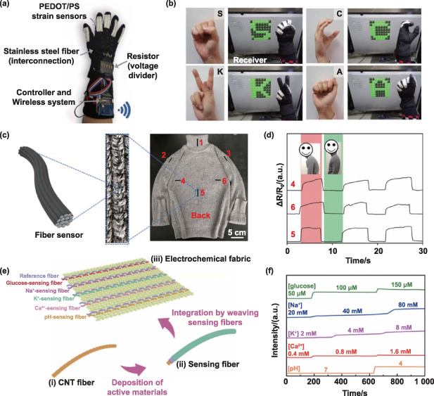
Figure 7. Textile sensors for wearable applications. (a) A smart glove consisting of strain sensors, interconnections, resistors, controllers, and a wireless communication system for (b) hand gesture recognition of American Sign Language. Reprinted with permission from [46]. Copyright (2017) American Chemical Society. (c) Illustration of fiber strain sensors woven at different locations of a garment shown in the digital photos, and (d) The sensor integrated smart garment for body posture monitoring and analysis based on signal patterns from distributed fiber sensors. Reproduced from [8] with permission from the Royal Society of Chemistry. (e) Schematic illustration for the fabrication of electrochemical fabric by weaving sensor fibers for glucose, [Na+], [K+], [Ca2+] and pH monitoring, and (f) chemical interference studies of the sensing fibers in electrochemical fabric. [198] John Wiley & Sons. © 2018 WILEY-VCH Verlag GmbH & Co. KGaA, Weinheim.
Download figure:
Standard image High-resolution image4.2. Actuators
Textile actuators, as energy transformers, are devices that transform input energies into various motions. Nowadays, large amounts of textile actuators have been developed to utilize different energy sources such as thermal heating [200], joule heating [10], electrochemical reaction [201], fluidic pumping [202], and magnetic energy [203] for the generation of mechanical output including shape change, bending, contraction, elongation, and force delivery. Their features of soft, compliant, light, and silent make them ideal candidates for wearable applications.
Fiber-based coiled linear actuators (FCLAs) are mostly made by nylon, polyethylene, PVDF, PET, CNTs, and composite fibers, and have advantages such as flexible, lightweight, and versatile for wearable devices at different scales. The actuation fundament of FCLAs is the anisotropic properties in the radial and axial directions. In other words, the actuation performance of FCLAs is mainly determined by the axial and radial expansion coefficients of materials activated by input energies. Many FCLAs fall under the classification of thermal-induced actuation. A pioneer FCLA was made by 1D twisted fishing lines and sewing threads. The coiled fiber contracts with high speed and stress by switching between cold and hot water baths (figure 8(a)). Upon heating of a heterochiral coiled fiber, the fiber generates an untwist torque that split coils away. Conversely, a homochiral coiled fiber generates an untwisting torque that pulls coils together [204]. Recently, advances in high actuation performance at relatively low actuation temperatures have been realized in a novel FCLA made up of polyimide and polydimethylsiloxane, as shown in figure 8(b). As heated from −50 °C to 160 °C, it achieved a high linearity contraction strain up to 20.7% with a 1.2 MPa load [10]. Apart from the two FCLA actuators, CNT coil actuators and fishing line-based actuators have also attracted much attention. A coiled, silicone rubber infiltrated CNT yarn generated a 34% tensile actuation [205], a fabric knitted by this CNT yarn reached a tensile contraction up to 33% with a mechanical work capacity up to 0.64 kJ kg−1 and a maximum power output of 1.28 kW kg−1. Fishing lines made by polyethylene and polyamide combined with other materials like shape memory alloy [206] can also enhance the mechanical properties. However, selecting the proper material with comfortable temperature arrangements is crucial to ensure the safety for users. FCLAs activated by heat in textile structures can achieve high strains and forces relative to body motions through various integration techniques. Despite their potential, significant obstacles remain when incorporating FCLAs into wearable electronics. One challenge arises from the slow actuation speed of thermal-induced actuators during the cooling process, resulting from the poor thermal conductivity of polymers and the surrounding air. Another challenge stems from the significant temperatures required to generate substantial strain and force, often exceeding 100 °C [10, 207]. While adding insulating layers could mitigate safety concerns, they also impede heat dissipation, further slowing the actuation speed.

Figure 8. Textiles for actuation applications. (a) Twisted and coiled polymer fiber actuator from fishing line and sewing thread to deliver large-stroke tensile actuation. The diameter of the coiled fishing line is 860 μm. From [204]. Reprinted with permission from AAAS. (b) Robotic hand actuated by FCLAs with an input power of 4.8 W via Joule heating. Machine-knitted actuator with three-layered fabric shell. [10] John Wiley & Sons. © 2020 WILEY-VCH Verlag GmbH & Co. KGaA, Weinheim. (c) Operates in a pneumatic way and (d) works as an assistive glove. Reproduced from [211]. CC BY 4.0.
Download figure:
Standard image High-resolution imageFCLAs can also be electrochemically energized with low voltages to quietly output forces and strains. Basically, the reversible electrochemical oxidation and reduction of active materials promote ions or solvent molecules to be incorporated with and expelled from active materials which in turn experience volume variation [208]. These processes can be accelerated and enhanced by electrodes with microstructure and molecular-scale active graphdiyne, resulting in high electromechanical transduction efficiency of 6.03%, large strain of 16.45%, and agile actuation frequency of 30 Hz for the electrochemical actuator [209]. A recent study of ion intercalation and the production of double-layer capacitance shed light on electrochemical actuators with dynamic spectrum regulation capabilities [210]. Such multifunctional actuators capable of emitting ultraviolet, visible, near-, and mid-infrared wavelengths may find applications in thermal camouflage robotics, optical communication, and radiative cooling.
In addition to directly output actuations, fibrous materials can also work as passive structures with various soft actuators to generate complex deformations in a programmable manner. Bladder type actuators reinforced with textile structures such as fibers [212], mesh fabrics [213], and fabrics integrated with inlays [211], are commonly used as workholders, part positioners, clamps, and soft brakes on belt conveyors. As shown in figures 8(c) and (d), the mesh-like actuator operates as an omni-fiber under the guidance of external mesh shell through the deformation of the internal elastomer bladder [213], which is constructed into a assistive glove to facilitate the grasp of objects. This three-layer fabric shell wrapping on the pneumatic actuator was digitally fabricated by machine knitting process with different knitted yarns, thus the actuation mode of the silicone tube could be manipulated by programming the three-layered shell [211]. Bandwidth remains a challenge depending on the chosen inflation pressure, which can dictate output forces [26, 214]. The total volume of actuators in a system exponentially affects bandwidth, implying that optimizing actuator structure design and fabrication strategies could overcome this issue. Additionally, most pneumatic actuators vent gas to the environment for deflation, but incorporating an extra vacuum chamber in fluidic systems can quicken the emptying rate. Overall, optimizing actuator structure design and fluidic system components has great potential to enhance pneumatic actuator performance, especially in addressing bandwidth and output forces.
4.3. Heaters and coolers
Textiles, as the interface between the human body and the ambient, play an important role in the regulation of thermal comfort among different environmental conditions [215, 216]. Advanced materials and composite structure for wearable heating/cooling devices have been developed to regulate the heat transfer between human body and external environment. Active personal thermal comfort systems can be implemented by using a variety of technologies such as, joule heating, thermoelectric (TE) temperature regulation, and electrocaloric cooling (EC). Joule heating utilizes the electro-thermal conversion, in which the heat is generated upon the passing of current in an electrical conductor. The heating power (P) of electrical conductors can be calculated by the square of the applied current (I) and the resistance (R) of the conductor, that is  based on Joule-Lenz law [217]. Certain aspects should be considered when integrating joule heating technology into wearable textile systems, including comfortability, sewability/weavability of the fabric, and durability of multiple cycles usage [218]. Joule heating fabrics are often fabricated via the modification of fiber/fabric surface and the embedment of electrically conductive materials. Carbon-based materials [219, 220], metal materials [221], and conductive polymers [13, 222] have been reported for developing joule heating fabrics. Ahmed et al [13] devised a facile and scalable dip-coating approach to develop stretchable, thermally stable, and electroconductive composite cotton textile with rGO and PEDOT:PSS (CGP), shown in figure 9(a). The electromechanical properties of CGPs were greatly enhanced due to crystallographic and intra-intermolecular hydrogen bond energy/distance modification. The composite heater presented rapid response (15–25 s), stable heating/cooling cycle, excellent durability to wash, and effective endurance against deformations up to 60% strain with excellent heating performance figure 9(b).

Figure 9. Textile electronics for personal thermal management. (a) Schematic of the fabrication strategy of a PEDOT:PSS and graphene-clad wearable Joule heater and (b) Time-dependent temperature change profile of the Joule heater under varying tensile strains ( = 0%, 15%, 25%, 40%, and 60%) at an applied potential of 15 V. Reproduced from [13] with permission from the Royal Society of Chemistry. (c) Overall and side view of the thermoelectric textiles as well as flexibility demonstration by optical images and (d) Time-dependent cooling effect of the thermoelectric textiles. Reproduced from [15] with permission from the Royal Society of Chemistry. (e) Fabrication process of an EC fiber based on the CNT yarn fiber as the inner conductor. From left to right: the SEM of CNT yarn, the optical microscope images of CNT yarn coated with a layer of P(VDF-TrFE-CFE), and a layer of SWCNTs, and the photograph of the resulting CNT yarn EC fiber and (f) the evolution of temperature at location 1, inset is the infrared image of EC fiber. [14] John Wiley & Sons. © 2020 WILEY-VCH Verlag GmbH & Co. KGaA, Weinheim.
Download figure:
Standard image High-resolution imageAlthough joule heating textiles have the potential in personal thermal comfort systems, they are still limited by the single mode of temperature control—heating. TE devices simply achieving both heating and cooling on the opposite ends are therefore very attractive for users. A TE device typically consists of pairs of p-type and n-type TE pillars which are electrically connected in series and thermally connected in parallel [223]. The working principle of TE device is the conversion of electrical energy into temperature gradient based on Peltier effect; heat can be carried by charge carriers from one side to the other side when current passes through the TE device, resulting in a temperature gradient across the device [224]. TE devices are ideal for small-scale heating/cooling systems thanks to many attractive features such as dual mode, no noise, and high stability. Hyper Ice, Inc. launched a product called Hyperice X which consisted of five rigid TE modules fixed on the surface of fabric pads, giving alternative heating and cooling treatment to tackle the pain and inflammation as well as reduce tension and aches around knees, respectively. However, the temperature uniformity of Hyperice X requires further improvement due to the poor thermal conductivity of fabrics. Except the existing commercial products, durable, stretchable, and mechanically stable TE devices have been developed positively, Zheng et al [15] reported a strategy to produce inorganic semiconductor based hierarchically ternary coaxial TE strings at large scale for semi-automatically manufacture. The fabricate 3D TE textiles used the elastic yarns as warp yarns and cotton yarns and TE strings as weft yarns. It not only presented excellent stretchability but also could be bent, twisted, and even knotted (figure 9(c)). Except for the high output density of 0.58 W m−2 at a temperature of 25 K, the TE textile stably produced solid-state cooling of 3.1 K in quiescent air at 26 °C and with a relative humidity of 60% shown in figure 9(d).
EC is another potential approach for personal thermal management and has attracted enormous attention in recent years. The simple principle is that the entropy and temperature of dielectric materials change consequently on the applying and removing of electric fields, referred as the electrocaloric effect [225, 226]. Commonly used EC materials such as ceramic, polymeric, and liquid crystalline materials with large relaxor ferroelectricity have been reported with high cooling performance [227]. The conventional structure of the EC device is fabricated as thin film capacitors with the EC material sandwiched between two parallel electrodes, whereas the film-shaped EC devices are difficult to be integrated into textile structures. In consideration of the portable and wearable EC devices with lower power consumption, Wang et al [14] fabricated EC fibers comprised of thin conductive wire core, P(VDF-TrFE-CFE) dielectric layer, and SWCNTs outer layer as the electrode. The fiber coolers were less than 160 μm in thickness and more than 8 cm in length. The Measured cooling temperature gradient of the EC fibers was 0.7 °C at an electric field of 100 V μm−1 across the dielectric layer. The cooling performance of the flexible fiber coolers showed insignificant degradation within 2000 cycles of repeated bending to a 2.5 mm curvature radius (figures 9(e) and (f)).
Developing effective wearable textile coolers and heaters that are lightweight, comfortable, and durable remains a significant challenge due to the complexity of the human body's thermoregulatory system. This system involves various factors such as body heat production, heat transfer, and environmental conditions, which interact in intricate ways. The integration of functional materials into textile structures offers many opportunities for the development of wearable coolers and heaters, but also presents some challenges. For instance, while rigid inorganic TE materials offer superior performance compared to other flexible materials, integrating them into textiles requires careful consideration of the mechanical flexibility of the textile, the electrical properties of the conductive materials, and the durability of the electronic components. Achieving a balance among cooling/heating performance, durability, and comfortability of resulting textiles is crucial. Another challenge is to create a scalable manufacturing process for this kind of heterogeneous integration. This typically involves multiple manufacturing processes that can be complex and costly to implement. Thus, finding innovative ways to address these challenges is critical to realize the full potential of textile-based wearable coolers and heaters.
4.4. Energy harvesters
Fiber-based devices have been extensively researched for energy harvesting from environment and human motion with enormous energy harvesting devices collecting photovoltaic [228], TE [229, 230], piezoelectric, triboelectric [231], and moisture-electric [232] energy. Textile products, especially clothing covering large surface area of human body, have good opportunity of exposure to the indoor and outdoor light to absorb the photons from man-made light sources or solar radiation. The textile-based photovoltaic system can absorb the photons at first to excite photoactive materials. The electrons that have been excited acquires more energy and likely to be ejected which thus generating the electric current [233]. The traditional photovoltaic devices are normally based on bulk metals or semiconductors, which are not suitable for wearable applications. However, with the development of thin film technology, the thin-film photovoltaic structures can be fabricated and give rise to the potential applications of textile-based photovoltaic cells. Wu et al have developed a wearable light-weighted textile-based solar cell made by polyester/Ag nanowires/graphene core-shell as anodes and transparent substrates which can achieve a power conversion efficiency of 2.27% and low areal density of 5.0 mg cm−2 (figure 10(a)) [18]. In addition, Achala Satharasinghe et al also developed a washable photovoltaic fabric that can power wearable and mobile devices with a continuously output of 2.15 mW cm−2 [19].

Figure 10. Textile electronics for energy harvesting based on (a) photoelectric effect. Reprinted from [18], Copyright (2017), with permission from Elsevier. (b) Thermoelectric effect. Reprinted with permission from [234]. Copyright (2018) American Chemical Society. (c) Piezoelectric effect. Reprinted from [235], Copyright (2015), with permission from Elsevier. (d) Triboelectric effect. [236] John Wiley & Sons. © 2015 WILEY-VCH Verlag GmbH & Co. KGaA, Weinheim.
Download figure:
Standard image High-resolution imageApart from light sources, heat from human body is also a harvestable energy source. Textile-based TE energy harvesters, which are designed and fabricated based on TE effect, can directly convert the waste heat from human body into electrical output. Comparing with the conventional TE devices for industrial applications, the textile-based TE devices are normally made by flexible materials or based on flexible structures, which can fulfill the requirements for wearable applications. Similar to the textile-based photovoltaic devices, the TE textile devices can also be made with TE materials and textile substrates such as yarns and fabrics via techniques including drop casting, ink printing, dip coating, spin coating, sputtering, thermal vapor deposition, and screen printing [237–240]. Apart from the deposition procedures, the textile-based TE devices can also be fabricated by embedding the bulk TE modules into the textile structures [241, 242]. Kim et al used the water containing polymer-based flexible heat sink along with the porous outer fabric (figure 10(b)) [234], the evaporation of the liquid from the outer fabric allowed the absorbed heat to be continuously released to the ambient, leading a temperature difference across the device that was sufficient to supply a 3.3 V power for the operation of a wearable electrocardiograph.
The mechanical energy generated by human motions can also be utilized and harvested through piezoelectric or triboelectric systems. Piezoelectric systems, involving the conversion between the mechanical deformation and potential accumulation of materials, are widely studied in the past decades [243–245]. Piezoelectric ceramics and single crystals are brittle and rigid with limited applications in wearable electronics [246]. Their organic alternatives, such as polymers and polymer composites are good candidates for textile energy harvesting systems [3]. With high processability in ambient, PVDF pure polymer and composites can be electro-spun and melt-spun into fibrous materials to build the textile electronic devices [247]. In addition to PVDF, polyvinyl chloride is highly processable for fiber making, Seol et al developed hybrid piezoelectric fiber composed of aligned piezoelectric BaTiO3 nanowires and flexible polyvinyl chloride polymer [235]. The fabric nanogenerator was constructed by woven hybrid fiber, metal copper wires, and cotton threads into the fabric, which output 1.9 V voltage and 24 nA current to power an LCD when attached on an elbow pad (figure 10(c)).
Comparing with other mechanical energy harvesting process, triboelectric energy harvesting, which relies on the frictional contact between surfaces and transfer of electrons, possesses many advantages, including high power density, conversion efficiency, and flexibility [248–250]. Combinations of different materials, including polymers, composites, and CNTs have been used in triboelectric energy harvesting devices [251]. Various textile-based triboelectric energy harvesting systems have been reported by adding materials as films or coating on the surface of yarns that are woven or embroidered into textiles [3]. Pu et al demonstrated a TENG fabric to harvest energy which is stored in a supercapacitor fabric, they successfully established a scalable self-charging power textile with output power of 4 V together with an energy density of the supercapacitor as 1.60 µWh cm−2 (figure 10(d)) [236]. Different from piezoelectric energy harvesting systems, the output voltage of the triboelectric energy harvesting system can exceed 100 V and may even reach several hundreds of volts. This is the highest output voltage for wearable energy harvesting systems for mechanical energy [252]. Furthermore, hybrid generator, which can incorporate two or more energy harvesting effects, have also been examined as highly efficient mechanical energy harvester [253, 254].
Overall, the development of textile-based electronics for energy harvesting has shown great promise. The choice of energy harvesting mechanism should be tailored to the specific conditions and requirements of applications. Continued research and development are expected to further improve their performance and expand their range of applications. Photovoltaic generators are effective for harvesting indoor and outdoor light. However, the performance of these devices is largely dependent on the area and absorbance of the light-absorbing surface. To optimize their efficiency, it is important to improve the design of the fabric in terms of different woven, knitting, and nonwoven structures. Additionally, as the active layer is located on the external surface of fabrics, it is important to consider factors such as rain, wear, and stretch during daily use. Textile TE generators, which can be found in the forms of fiber, yarns, and fabrics, have a broad range of applications as long as there is a temperature gradient between the human skin and surroundings. However, the output power of these generators is relatively low compared to that of piezoelectric or triboelectric generators. Piezoelectric and triboelectric generators based on fibrous materials offer many advantages, including high power density and conversion efficiency. However, they also possess limitations in reliability and durability. It is important to consider the mechanical strength of the devices, as they operate in dynamic conditions where continuous mechanical deformation and relative movement occur in functional fibrous structures.
4.5. Energy storage devices
When there is no energy available for harvesting to generate electricity, textile electronics with the ability of energy storage can continuously feed a considerable amount of energy to other electronic devices when needed. In this section, we summarize four common energy storage devices, including lithium-ion batteries, metal-air batteries, electric double-layer capacitors (EDLCs), and pseudocapacitors, that are available in textile equivalents.
Lithium-ion batteries featuring with high energy density (up to 250 Wh kg−1 or 800 Wh l−1), good cycling stability, high operating voltage, and environmental friendliness have received widespread attention in to reliably power portable textile electronic devices [255]. At early stage, planar metal electrodes were replaced with electrically conductive metal wires, however, the mismatched rigidity between metal wires and textiles hindered their application [192]. In contrast, carbon materials, such as CNT and graphene, are widely used as electrodes or active materials for energy conversion devices due to their excellence in mechanical flexibility, tensile strength, and electrical conductivity [256–258]. However, many boundaries among CNTs in the conductive network reduce the efficiency of charge transport of CNT fibers. This is often addressed by integrating fibers with active components. For example, Lin et al deposited Si on the surface of multiwalled carbon nanotubes (MWCNTs) to fabricate aligned MWCNT/Si composite fiber electrodes (figure 11(a)). The composite fiber exhibited high specific capacity and cycling stability, and was used for fabricating flexible linear cells [259].
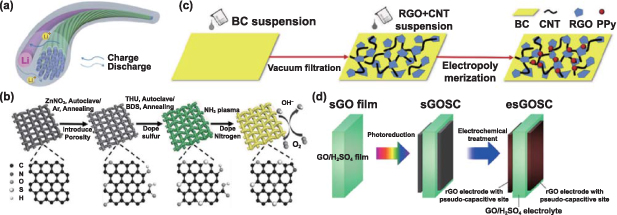
Figure 11. Textile electronics of energy storage devices. (a) Aligned MWCNT/Si composite fiber as a working electrode. [259] John Wiley & Sons. © 2013 WILEY-VCH Verlag GmbH & Co. KGaA, Weinheim. (b) The preparation of N, S codoping CC and liquid rechargeable Zn-air batteries. [260] John Wiley & Sons. © 2018 The Authors. Published by WILEY-VCH Verlag GmbH & Co. KGaA, Weinheim. (c) The fabrication of PPy/RGO/CNT/BC (Bacterial Cellulose) flexible electrode. Reprinted from [261], Copyright (2019), with permission from Elsevier. (d) The fabrication of GOSC. Reprinted with permission from [262]. Copyright (2017) American Chemical Society.
Download figure:
Standard image High-resolution imageIn recent years, metal-air batteries have often been used in combination with flexible electronics for textile electronics due to their high energy density. Depending on the anode used, metal-air batteries can be classified as Zn-air batteries [263], Li-air batteries [264], Al-air batteries [265], Mg-air batteries [266], Na-air batteries [267], etc. Among them, Zn-air batteries are identified as the most desirable and relatively mature energy storage system due to their high theoretical energy density (1086 Wh kg−1), high safety, and low cost [268]. In addition, the intrinsic natures of nontoxic, eco-friendly, and handy of Zn anode and aqueous electrolyte [269] make Zn-air batteries promising for wearable textile electronics. But the rigidity of conventional electrodes restricts their practical applications. For this reason, Zhao et al used flexible commercial carbon cloth (CC) as the electrode substrate for a rechargeable Zn-air battery (figure 11(b)) [260]. After several deformation cycles of folding and unfolding, the battery still worked well because the flexible catalytic electrode could alleviate the mechanical changes and pressures. For metal-air batteries, numerous flexible batteries with high energy density have already been demonstrated successfully [266, 270], while most of them come in the form of large film structure with limited flexibility, still below the requirements of wearable textile electronics.
In EDLC, the capacitance comes from the electrostatic charge accumulated at the electrode/electrolyte interface. Because of the two separate charge layers at the positive and negative electrolyte interfaces respectively, the capacitance of EDLC is higher than conventional capacitors [271]. Similar to the lithium-ion batteries, various carbon materials such as activated carbon, CNTs, and graphene are widely used as electrode materials of EDLC [272, 273]. For example, Bai and coworkers developed graphene/CNT/bacterial cellulose architecture as flexible substrate (figure 11(c)) with excellent flexibility and high conductivity, both high electrochemical performance and remarkable mechanical properties were achieved in the supercapacitor [261]. The textile supercapacitors could be fabricated by the deposition of active materials onto flexible fiber structure [274] and fabric structure [275], their capacity could maintain at 95.5% and 93.3% after 1000 and 10 000 bending cycles, respectively.
In pseudocapacitors, energy storage takes place via Faraday redox reaction at the electrode surface. Typically, active materials with high specific surface area are used on flexible electrodes with high electrical conductivity, are crucial for high capacitance, energy density, and cycling stability. Metal oxides including MnO2 [276] and RuO2 [277] can be deposited onto carbon-based conductive textile fibers, forming a porous structure with large area capacitance. Conductive polymers such as PANI and PPy, can be combined with CNTs to produce flexible composite films with high mechanical durability. For example, CNTs/PANI composite films were reported to maintain 100% specific capacitance except after 200 stretches or 1,000 bends [278]. Similarly, the flexibile pseudocapacitor consisting of electroactive CNT-PPy on flexible CC electrodes with reduced interfacial resistance and promoted ion diffusion between electrode and electrolyte displayed unaltered CV profile in either folding state or after 20 cycles of bending [279]. Furthermore, a combination of carbon nanomaterials is used as pseudocapacitive materials for synergistic effects [280]. For example, Ogata et al reported a flexible solid state rGO/rGO/rGO supercapacitor consisting of a graphene oxide electrolyte/separator with H2SO4 intercalation and a pseudocapacitor rGO electrode (figure 11(d)); this device could provide an area capacitance of 14.5 mF cm−2 and a bulk energy density of 1.24 mWh cm−3 [262]. The synergistic effects of stacking structure delivered high volumetric energy density while maintaining an ultrathin construction. These advantages are attractive for developing textile pseudocapacitors with low density and high device performance.
In recent years, the demand for energy supply is increasing accompany the advances of textile electronics. To enhance the electrochemical and mechanical properties of textile-based energy storage devices, making them suitable for use in a wide range of applications, such as apparel, home, sports, healthcare, and construction. There are still significant challenges that must be addressed.
One major challenge facing textile energy storage devices is the contradiction between flexibility and storage capacity. Flexible fibrous substrate with higher deformability typically offers lower loading and weaker interfacial bonding of active materials when compared with bulk and rigid substrates [281]. The selection of active materials, from another angle, can balances the two factors. Carbon-based active materials including carbon fibers, CNTs, mesoporous carbon, and graphene-based materials, are often used with textile materials due to their high specific surface area and mechanical stability. In addition, excellent interfacial bonding between active materials and flexible substrates is important in wearable electronics, as they are subject to bending stresses during operation.
Another crucial issue is safety, as these devices are expected to be used near or attached to human skin. For lithium-ion batteries and capacitors, problems such as overheating, electrolyte leakage, or even explosion can occur during repeated charging and discharging due to the redox reaction of the electrode materials. Gel-based electrolytes, as safer alternatives which have emerged in recent years, can be excellent candidates because of their high safety factor. Moreover, flexible and lightweight encapsulation materials and packaging technologies are urgently needed. Commonly used polymeric materials including silicone rubber and PET have poor barriers to water vapor and oxygen, leading to corrosion of some active materials, loss of performance, and solution leakage [282].
Finally, cost issues cannot be ignored, as the production of advanced materials and the manufacturing of sophisticated devices can be expensive and time-consuming. Cost considerations must be addressed for these devices to become commercially viable.
4.6. Displays
Wearable display with higher integration offers with a higher degree of convenience of usage, like lightweight, portable, and body-fitting, providing a potential humanmachine interface for different applications, like sports training, healthcare, and military. Since its development is still in the initial stage, current flexible displays technologies face many challenges in the aspects of contrast ratio, stability, power consumption, resolution, viewing angle, and production yield [283]. Moreover, wearable applications have posed higher requirements, especially contrast ratio, biocompatibility, and stability. This section briefly discusses the potential of different display technologies and their recent developments.
A LED is a pn junction composed of p-type silicon (Group III) and n-type silicon (Group V) grown on sapphire materials. During light emission, the dominated holes in the p-type material combine with the dominated electrons from the n-type material to form a valence band to emit photons. The semiconductor gap controls the emission wavelength. LEDs exhibit high luminous intensity (>100 000 cd m−2), long lifetime (∼10 years), and wide working temperature between −100 °C and 120 °C [284, 285]. This is attractive in developing wearable displays with high contrast ratio and good reliability. However, LEDs are not flexible and stretchable due to material limitations. The downsize of LEDs to microscale LEDs or nanoscale LEDs allows the integration of LED chips as pixels into textile structures including fabrics, yarns, and filaments. For instance, a fabric display is fabricated by integrating filament circuit embedded with LED chips, less than 2 mm width, into woven fabric (figure 12(a)) [180]. Moreover, an illuminated electronic yarn is developed by embedding copper wires and LEDs into a polymer micro-pad with the knitted sleeve to fabricate the electronic-yarn (figure 12(b)) [286]. However, the efficiency and size of LEDs are positively correlated. For instance, the external quantum efficiency (EQE) of GaN LED chip drops from 12% to 2% when the size decreases from 500 µm to 10 µm [287]. This may pose a challenge to electrical safety as the current and voltage of wearable displays are over the biological safe threshold.
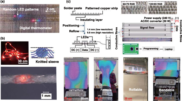
Figure 12. Textile displays of LEDs. (a) Photograph of the integration of copper filament circuit (2 mm width) with LEDs into woven fabric. [180] John Wiley & Sons. © 2019 The Authors. Published by WILEY-VCH Verlag GmbH & Co. KGaA, Weinheim. (b) Electronic yarns embedded with LEDs. Upper left: photograph of the illuminated electronic yarn. Upper right: A schematic image of the electronic yarn structure. Bottom: an optical image of LED electronic yarn. Reproduced with permission. Reproduced from [286], with permission from Springer Nature. (c) RGB smart textile display system. Top: Overview of fiber LED and display fabrication: Left: fiber LED fabrication. Right: interconnection between display circuit and corresponding fiber LED. Bottom: mechanical stability of the display system of 34-inch under folding, rolling, and bending. Reproduced from [288], with permission from Springer Nature.
Download figure:
Standard image High-resolution imageLED textile displays are generally still in the embryonic stage as these wearable display prototypes only comprise a limited number of LEDs. Its pixel is still away from commercial rigid display (1920 × 1080), and its imaging and applications are quite narrow. This is restricted by the immature circuit development for wearable displays (as mention in section 2.2) and poor connection between circuits and chips. However, one prominent advantage of LED display over other flexible display technologies is that the advance of integrated circuit technology has enabled the LED chip to be equipped with built-in integrated circuit to allow the control each pixel in the textile display. Figure 12(c) demonstrates a flexible smart textile RGB display system, in which circuits are used as the weft yarns to weave with normal warp yarns [288]. This display was bendable and foldable, but it was still uncomfortable for wearable applications. Although some achievements have been made, LED textile displays still lack comprehensive evaluation covering both textile and electronic aspects, and face many issues, such as light unevenness, pixel repair method shortage, and wavelength shift in the textile structure [289, 290].
An organic LED (OLED) is based on the electroluminescence in organic materials, which are organic conjugated small molecules or light-emitting polymers. It features with flexibility, ultrathin profile, wide viewing angle, and ultrafast speed [291]. In the past few decades, the original OLED formed four layers of cathode, anode, hole injecting layer, and charge injecting layer has been advanced with the introduction of hole blocking layer, charge blocking layer, and emission layer to maximize the quantum efficiency [292, 293]. The common organic light emitting materials include polyindole, polymethyl acrylate, PEDOT, and poly(2-methoxy,5-(2-ethylhexyloxy)-1,4-phenylene-vinylene [292]. Since they are soluble in many solvents, OLEDs can be produced with high yield via the solution process. To develop fabric displays based on OLEDs, a fiber-shaped OLED is usually fabricated as unit. Figure 13(a) illustrates an OLED fabric comprised of warp OLED fibers produced by depositing OLED layer, MoO3 and Al onto PET film strips and weft Ag/PET strips [294]. Similarly, OLED fibers with 90 µm in diameter was developed via coating PET fiber [21], and were further integrated into knitted fabrics to show different alphabets (figure 13(b)). OLED flexibility from material endows itself compatibility to conventional textile with better comfortability. However, the pixel density of OLED textile display is limited since only a half area of the fabric can emit light due to its working principle. A fabric-based OLED with addressable network and tailored thin-film encapsulation was reported with larger emission area. Each OLED fiber consisted of emission pixels with a common conductor as anode and individual cathodes over the top of encapsulation (figure 13(c)) [295]. Both of the weft and warp fibers operated as light emitters. However, most textile OLED displays are small in size and only can emit single color. An additional reliable connector compatible to standard electronic product is necessary and need to be investigated for wearable display devices. In addition, OLEDs have a higher requirement for the encapsulation technique due to their quick oxidation upon exposure to oxygen and moisture.
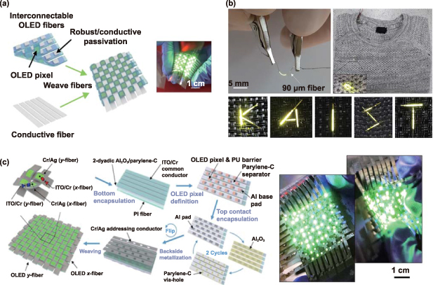
Figure 13. Textile displays of OLEDs. (a) Schematic fabrication and structure of OLED fabric display (left) and OLED fabric photograph (right). Reprinted with permission from [294]. Copyright (2020) American Chemical Society. (b) OLED fiber: Photographs of OLED fibers with a diameter of 90 µm and the textile electronic application of alphabet display. Reprinted with permission from [21]. Copyright (2018) American Chemical Society. (c) Fabric-based OLED display with large emission area. Left: Fabrication procedure of the OLED fabric, in which both warp and weft fibers can emit light, and the corresponding structure. Right: Photographs of the illuminating OLED fabric without and with bending. The scale bar is 1 cm. Reproduced from [295], with permission from Springer Nature.
Download figure:
Standard image High-resolution imageQuantum dot LEDs (QDLEDs) are based on quantum dots (QDs) defined as the nanometer (2–10 nm) semiconductor materials [296]. QDLEDs characterizes with high color purity (full-width-at-half maximum: ∼ 30 nm), high brightness (∼200 000 cd m−2), and low operating voltage (<2 V) [297–299]. QDLEDs with tunable emission upon the adjust of material size and composition produce color covering 90% of BT. 2020 color gamut as human eye detection range [300]. To ensure stable emission, QDs are usually synthesized into the core-shell structure that consists the emissive core made up by co-precipitation and hot-injection approaches [296, 301], and the protective shell in-situ grow on the core surfaces in a controllable manner with cation exchange technique and successive ion layer adsorption and reaction method. After that, additional organic ligand or nonbiological species can be attached to the shell, like antibodies, streptavidin, and lectins, to modify the surface properties, like water solubility, stability, and biocompatibility. QDLED can be much thinner than OLED, since the emission material is replaced by QDs. A skin-attachable and ultrathin (∼5.5 µm) QD display (figure 14(a)) was fabricated with the brightness of 44 719 cd m−2 at 9 V [302]. However, QD displays are still far away from practical applications because QDs are sensitive to water, oxygen, UV, and thermal heating. QLEDs also face cytotoxicity issue which comes from a composing element of Cadmium that is harmful to human and the environment. There is an urgent need to develop biocompatible materials to replace Cadmium.
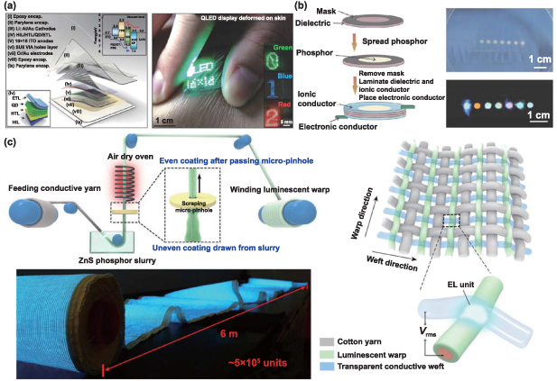
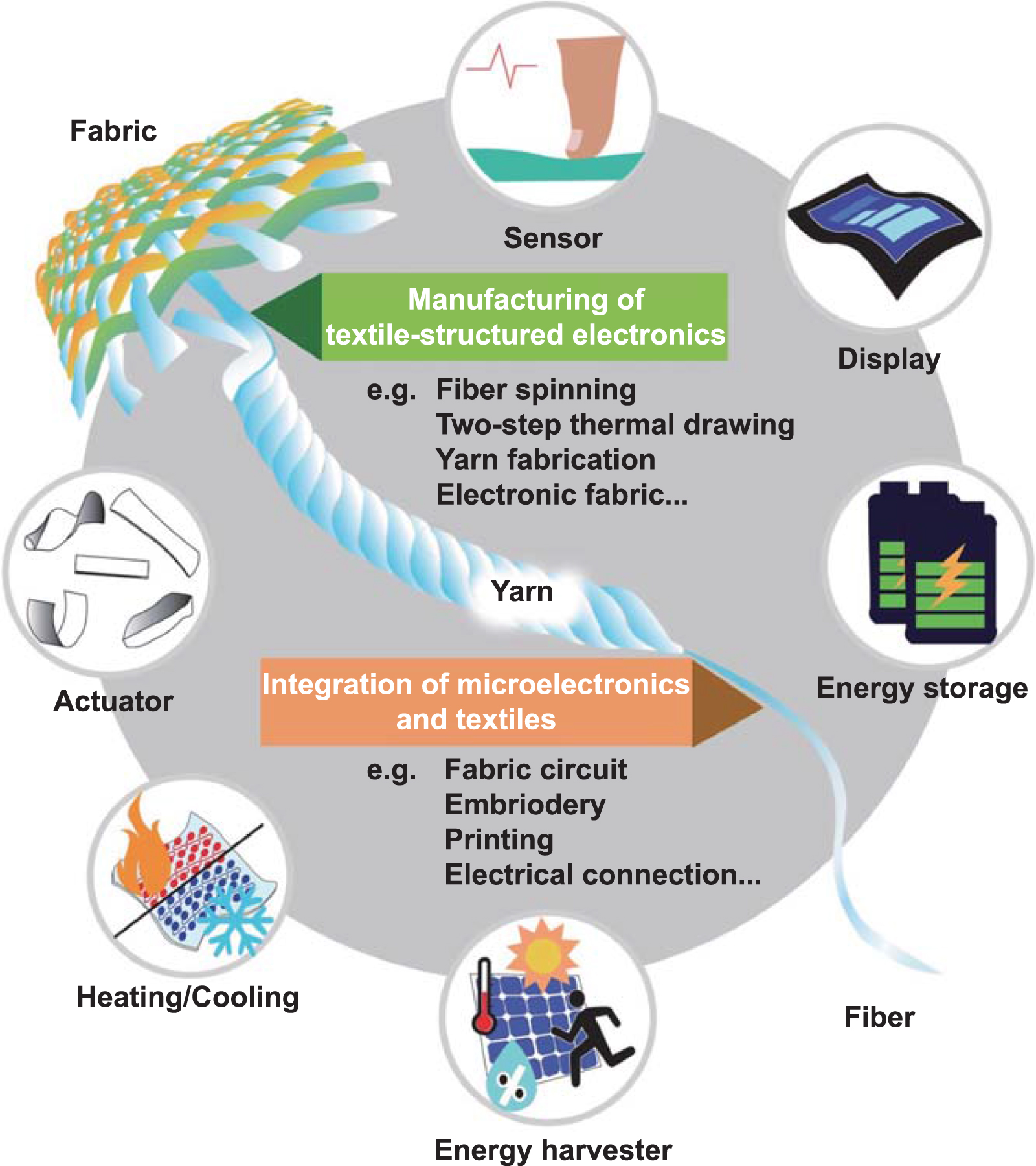
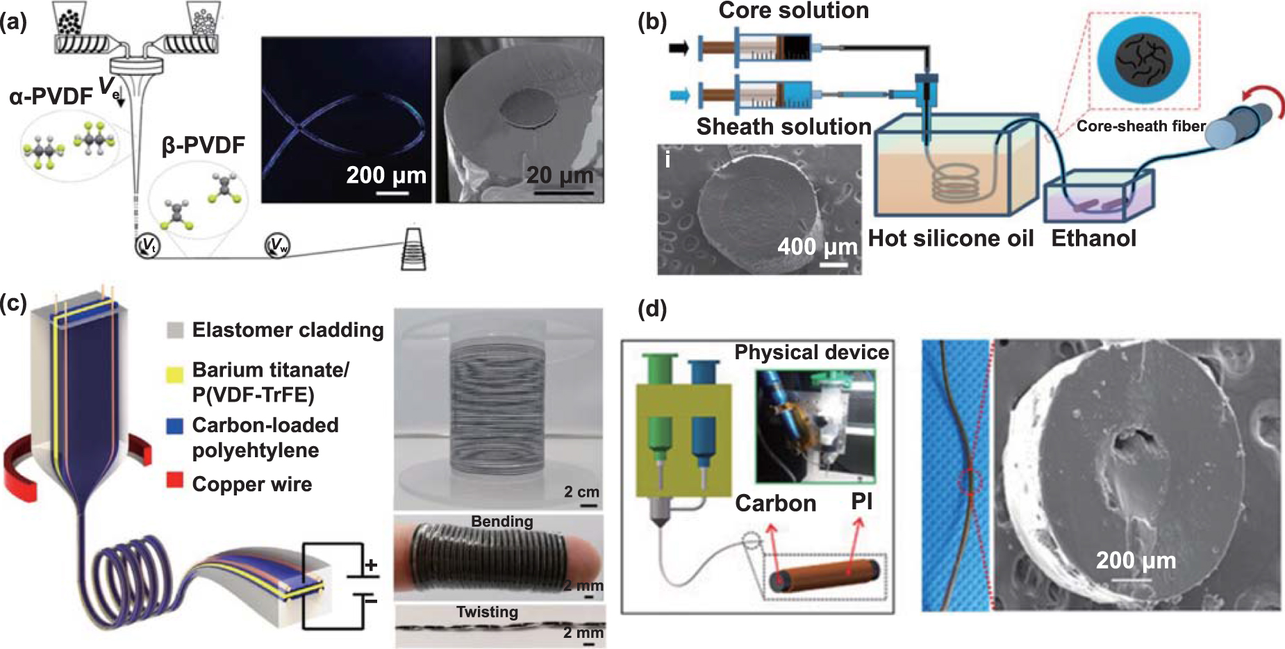
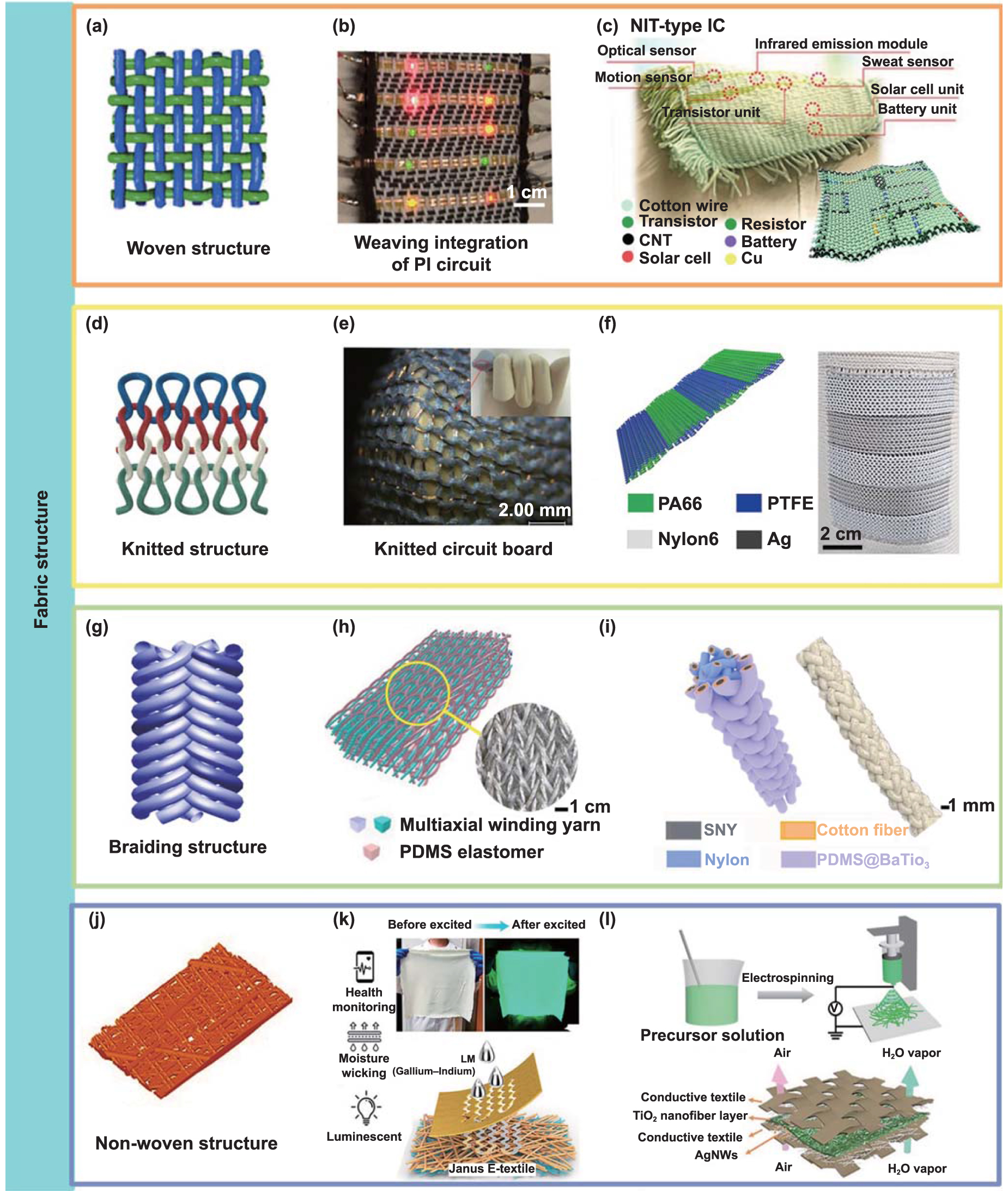
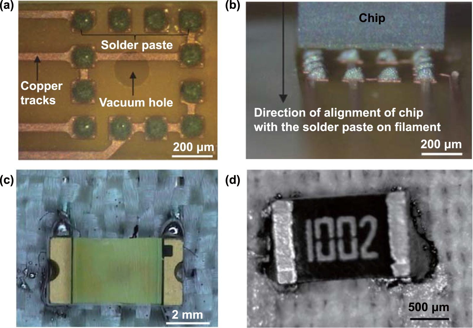
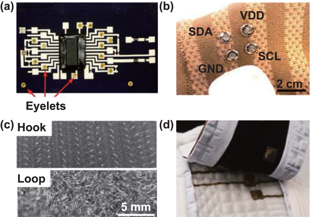
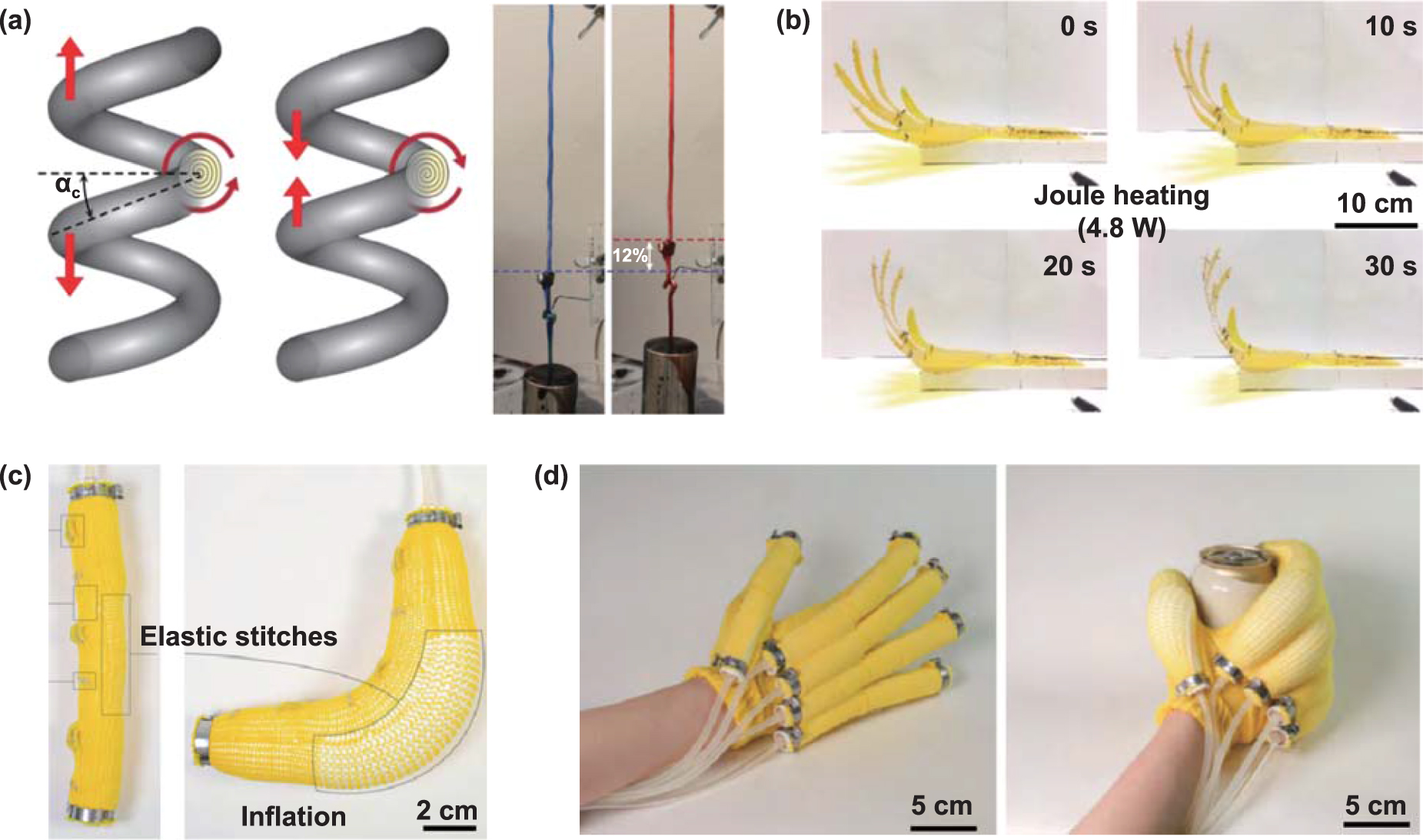
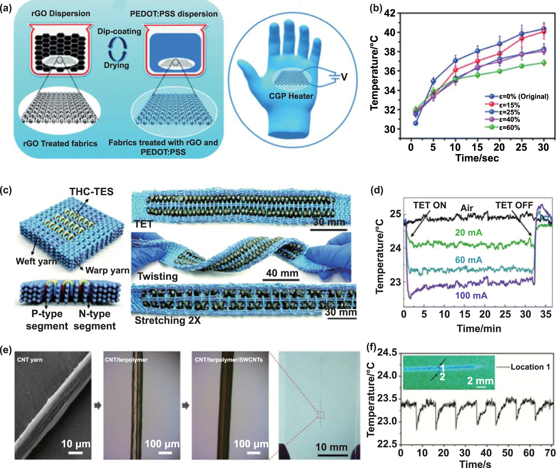
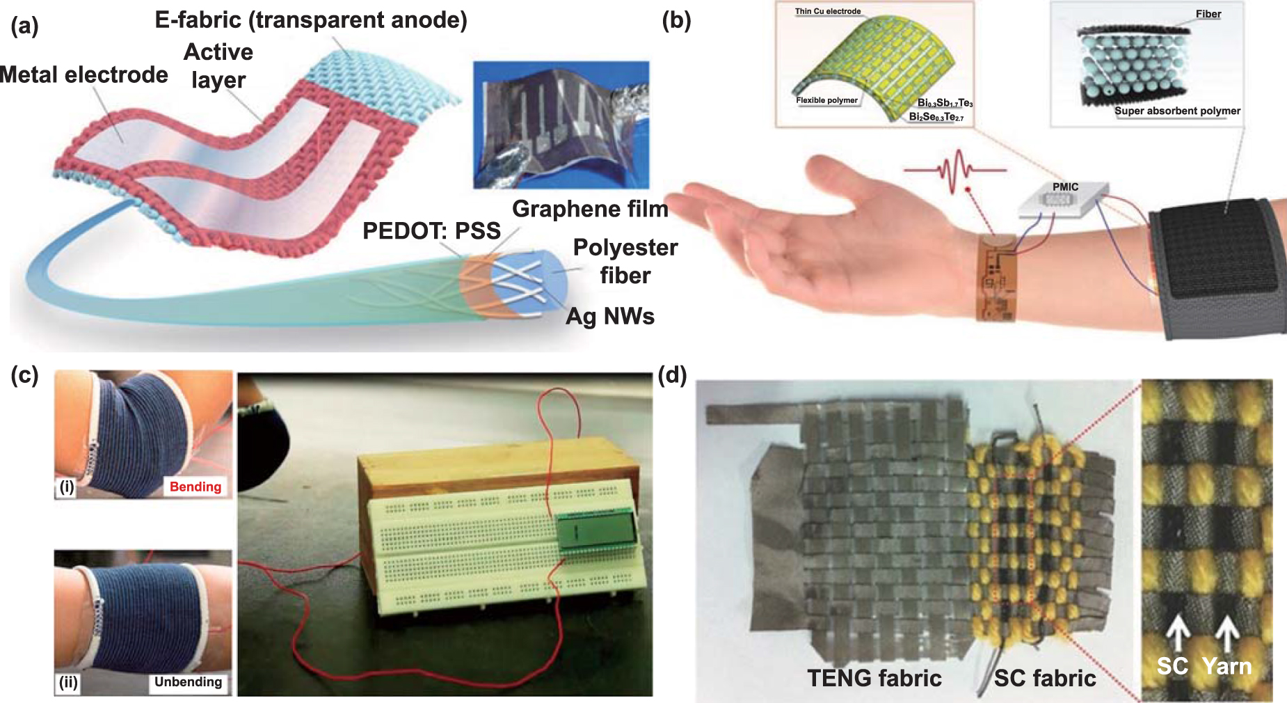
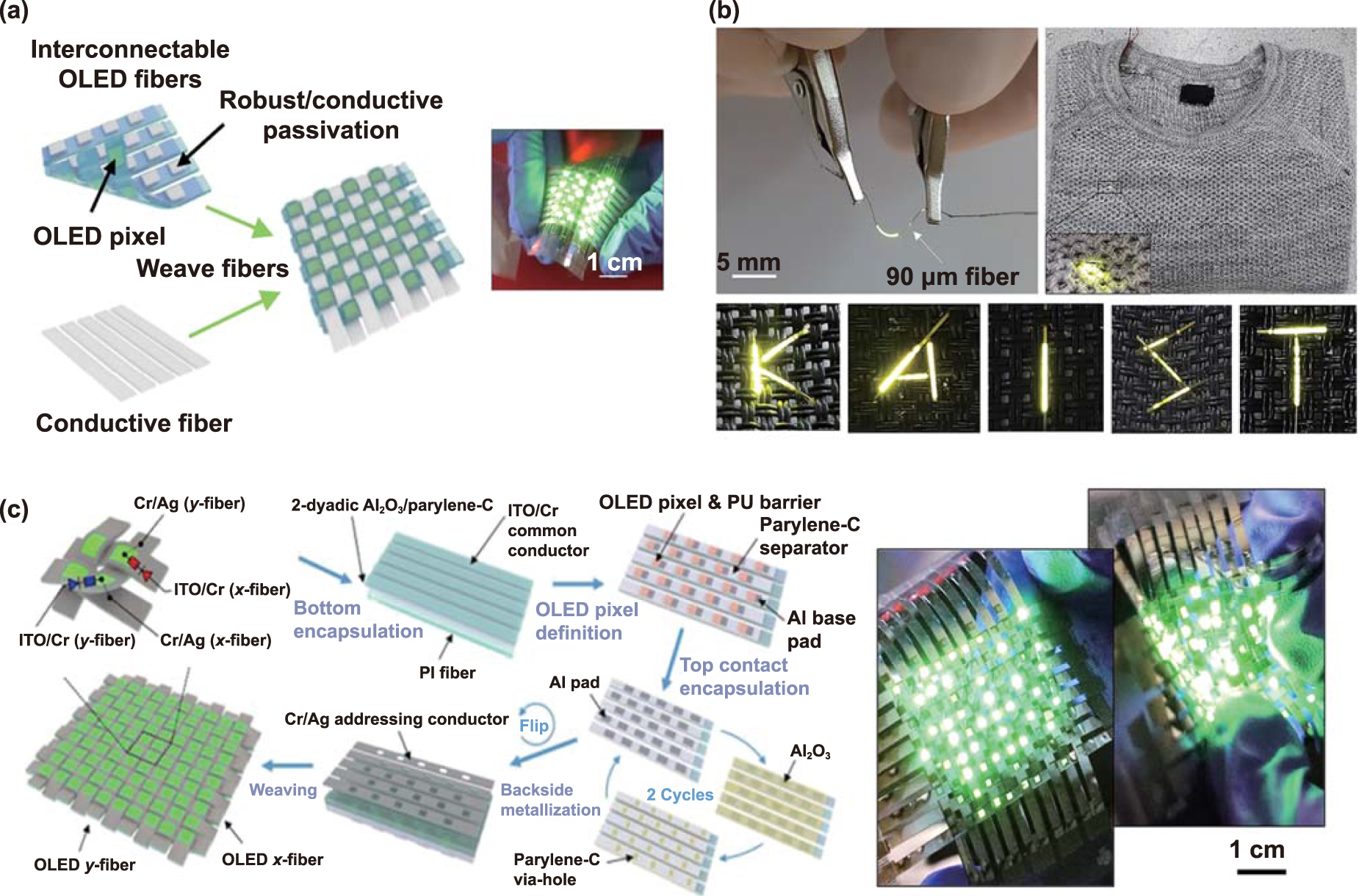
Figure 14. Textile displays of QSLEDs and other electroluminescent technologies. (a) Schematic illustration of the structure and mechanism of the QD display and a photograph of the display attached on human skin. [302] John Wiley & Sons. © 2017 WILEY-VCH Verlag GmbH & Co. KGaA, Weinheim. (b) Schematic illustration of the structure of the fabric-based electroluminescent device, and photographs of the device without and with illumination. [303] John Wiley & Sons. © 2015 WILEY-VCH Verlag GmbH & Co. KGaA, Weinheim. (c) Large-area flexible electroluminescent display. Upper left: Electroluminescent yarn fabrication procedure. Bottom left: photograph of the large-scale flexible display with a size of 6 m × 25 cm. Right: Weave structure and working mechanism of the fabric electroluminescent device. Reproduced from [20], with permission from Springer Nature.
Download figure:
Standard image High-resolution image
Besides the above three electroluminescent technologies, the activation of inorganic polycrystalline solids, like phosphor powder, with alternating current is another potential route. It can fabricate large-scale displays to generate homogenous light at a low cost. During light emission, the phosphors, sandwiched between dielectrics and electrodes, are activated to a higher energy level by alternating electric fields, and then emit photons [304]. An early stretchable fabric-based electroluminescent device was fabricated by laminating several sandwiched luminescent units onto the fabric (figure 14(b)) [303]. Recently, continuous lengths of luminescent warp fibers and transparent conductive weft fibers were fabricated via the solution coating of ZnS phosphor dispersed in polymer matrix on silver-plated conductive yarn and the melt-spinning of PU gel doped with ionic liquid, respectively. These electronic fibers were them woven with cotton yarn into a 6 m × 25 cm large scale textile display (figure 14(c)) [20]. The main challenges for this type of display include monochrome light emission, luminance degradation, shorter lifetime, lower contrast ratio, and lower discrimination ratio [305].
The textile display acting as an important visual information pathway is critical to the integration of wearable systems and offers great opportunities for interactive and immersive applications. However, there are many challenges to develop an appropriate, stable, and practical textile display system. One major challenge is the functional defect or incomplete system. Current research mainly focuses on luminous elements of the display instead of the whole system. The basic display system is responsible for receiving the screen information from the serial port, placing it in the frame memory, generating serial display data, and scanning control timing that the luminous unit can identify. There is limited research on signal processing unit of textile displays, and many of them are still relied on rigid PCB. In addition, most of the mentioned display techniques cannot control each luminous element individually. Display system functionality advances with applications. An example is video display, in which greyscale can be controlled; the communication display can store and automatically play images. Current textile display function is still far away from rigid display.
Beside the mono-function of display system, wearable properties related to textile, like comfortability, conformability, and durability, are backward. Some of the textile displays are bendable, foldable, and stretchable, while their long-term resistance to these mechanical forces has not been quantified and washability is also not considered. Furthermore, most integrations between textile and display are limited at the fabric level. This is restricted by the material stability, electrical connection reliability, technique coordination between textiles and displays, and encapsulation quality.
Another serious limitation is the applicability of textile display in the aspect of design and function for wearable application. Display performance, like pixel, contrast ratio, and luminance, need to adapt to application scenarios (e.g. distance between user and image, sunlight change, and image difference). Due to this, wearable applications need to be analyzed and specified to design appropriate textile display. The integration of textile and display also influences the optical performance of display, differ to rigid display.
5. Conclusions and outlook
Textile electronics made up of fibrous materials and electronic components have intrinsic properties combining conformability with high durability while providing lightness, breathability, flexibility, and adaptability of textiles with the functionality, connectivity, and intelligence of electronics. Both the manufacturing of textile-shaped electronics and the integration of microelectronic with textiles are important to prepare textile electronics with desirable properties. As described in this review, a broad range of manufacturing and integration approaches have been developed in recent years, including the manufacturing of hierarchical textile architectures in the form of fibers, yarns, and fabrics that serve as the basic building blocks of textile electronics; the development of electronic devices with textile building blocks and active materials to seamlessly merge electronic functionalities within fibrous structures; and the integration of microelectronic components into/onto the textile platform to facilitate the manufacture of sophisticated wearable electronic systems uncompromising with wearable comfort and electronic reliability. A broad range of textile electronics come into being with knowledge and techniques, and exhibit many intriguing properties, which are being explored in many exciting niches, among physiological signal monitoring, soft robotic actuation, wearable devices powering, human-machine interaction, and many more. While research on textile electronics has progressed quickly, many tasks remain for wearable microelectronic textile systems to achieve consumer-level performance.
The first is the scalable fabrication of fibrous material as it is directly related to the performance, productivity, and cost of wearable devices. Textile engineering has given textile electronics the inspiration for manufacturing. However, stretchability and flexibility are often achieved at the expense of electrical performance through coupling active materials with inactive polymer matrix. Leveraging and improving traditional textile processing techniques will lead to an immediate effect on mass production compared to sophisticated laboratory techniques. Meanwhile, the inclusive development of new strategies to efficiently construct architectures of active materials could have a revolutionary impact on the contradiction between electrical and mechanical performance. The integration of multiple functional units with reliable interconnection patterns is crucial for the optimum and consistent performance of the wearable system. Efficient approaches originating from textile techniques for connection with flexible electoral conductive fibers/yarns show their advantages in maintaining the flexibility of the textile electronic systems.
Washability is a major concern of the market success of textile electronics in fields like healthcare and sports. It is imperative that they endure repeated washing procedures to maintain hygiene and usability. However, inadequate washability remains a significant challenge for textile electronics. It is necessary to establish a theoretical foundation and develop feasible methods for sufficiently improving washability. Theoretical foundation can be built by conducting systematic and comprehensive research to identify the influencing parameters of washability, the types of washing damage to textile electronics, and weak points of textile electronics subjected to washing procedures. This knowledge can guide the development of targeted approaches to achieve reliably washable e-textiles. In terms of specific fabrication approaches, washability enhancement strategies must be adopted based on the fibrous substrate, functional materials, and processing involved in designing, manufacturing, integrating, and packaging the textile electronic systems. One such approach is the surface modification of the substrate using proteins, cross-linkers, plasma, and etc. This modification introduces functional chemical groups on the surface of fibrous materials to enhance bonding and adhesion between the substrate and functional materials, thereby improving washing endurance. Alternatively, the encapsulation of conductive textiles with thin layers of polymers such as TPU, PDMS, and epoxy resins are also effective in protecting the conductive pattern from mechanical, water, and chemical attacking during washing. However, protective encapsulation should not impair the textile properties. Therefore, protecting layer made up of textile materials like zig-zag stitches of insulating threads on the conductive tracks would be a promising solution. In addition to developing flexible and lightweight encapsulation layers for conductive trucks and interconnectors to ensure washability and wearability, future developments could focus on improving fabrication methods and developing new processes for producing hydrophobic surface structures and coatings for conductive yarns and fibers.
It is essential to consider the safety of textile materials when fabricating wearable textile electronics, since they will often come into contact with the human body for an extended period of time. To avoid any exposure or leakage that may harm human health, conductive electrodes incorporated with CNTs and graphene oxide as well as electrolytes containing heavy metal elements and toxic organic components should be well encapsulated. Following by an enormous challenge to develop an encapsulation that is tolerant of mechanical deformation and environmental impact, as well as compatible with human skin, without affecting the breathability, comfort, flexibility, and other inherent properties of the substrate.
At the same time, a highly integrated system with many distributed electronic components put forward higher requirements for energy consumption. Hence, much effort needs to be put into miniature energy supply devices that pursue higher energy capacity, energy conversion efficiency, and so on. Energized textile electronic devices can pose a risk of electrical shock due to excessive leakage currents, which may result from worn or defective circuitry or accidentally exposed components. It can also be expected that the next-to-skin textile electrics often heat up with time, causing skin damage with prolonged use. Thus, the development of fibrous materials with high thermal conductivity and small devices with active cooling ability for thermal management in textile electronics is a concerning direction. With the development of evaluation platforms for textile electronics, including instruments, protocols, and standards, risks associated with wearable textile electronics may be greatly reduced.
Acknowledgments
The authors wish to acknowledge funding support from Research Grants Council, Hong Kong (Nos. 15201922E, 15203421E, 15202020E, 15201419E), Innovation and Technology Commission (ITC) of Hong Kong SAR Government (No. ITP/031/21TP). Ma, Tang, Liu, Yang and Hui acknowledge postgraduate scholarships from the same sources. Pu has been supported by the Distinguished Postdoctoral Fellowship from Hong Kong Polytechnic University. Xiong is supported by ITC's Postdoctoral Fellowship.