
Abstract
This second study in a two part series investigates the synthesis of Co-free single crystalline Mg-doped LNO via the one-step lithiation method. The synthesized materials were characterized by scanning electron microscopy, X-ray diffraction and particle size analysis to understand the impact of synthesis conditions. Higher heating temperatures promoted grain growth but also increased the Ni content in the Li layer. Increasing the Li/TM ratio does not seem to have an effect on grain growth at lower temperatures but influences the formation of Li2O impurity. The separation of particle aggregates is required to improve the cycling performance of the material. The utilization of a lower temperature step after the calcination step can reduce the Ni content in the Li layer below what would be expected at the calcination temperature, and this can be used to grow larger grains while keeping an acceptable amount of Ni in the Li layer. However, all single crystalline materials are still not yet electrochemically competitive with polycrystalline materials and have lower capacities, higher irreversible capacities and similar cycling fade. The lower capacities of single crystalline materials stem from increased kinetic hindrances to Li diffusion. Cycling single crystalline materials at 55 °C can recover ∼20 mAh g−1 of discharge capacity and yield similar irreversible capacity compared with polycrystalline cells cycled at 30 °C.
Export citation and abstract BibTeX RIS

This is an open access article distributed under the terms of the Creative Commons Attribution 4.0 License (CC BY, http://creativecommons.org/licenses/by/4.0/), which permits unrestricted reuse of the work in any medium, provided the original work is properly cited.
In part I of this series on the synthesis of single crystal (SC) Co-free Ni-rich positive electrode materials for Li-ion batteries, the use of a two-step lithiation method to synthesize LiNiO2 (LNO) doped with 5% Al or 2.5% Mg was investigated. 1 The two-step method was introduced as a potential pathway to avoid the formation of Li5AlO4 impurities in Al-containing Ni-rich materials, 2,3 and the method consists of a first step that heated the material at high temperatures but with less Li for grain growth and then a second step at lower temperature to fully lithiate the material. The synthesis of single crystalline materials was achieved. It was found that the presence of Li or Mg is required for grain growth and higher temperatures enhance grain growth as well. Previous work on SC materials have reported the importance of Li 4–13 and higher temperatures 3–10,12–18 on single crystal growth but the impact of Mg on grain growth in these materials was unknown. It was hypothesized that the reason Mg was able to promote grain growth but not Al is due to Mg being a better diffuser in these materials than Al. 19,20 Part I found that insufficient Li in the first step results in the grain growth of rocksalt materials and may lead to the formation of rocksalt impurities stemming from incomplete lithiation. A satisfactory procedure was used to grow particles to a suitable size and it was found that a second step temperature of 750 °C was able to reduce the Ni content in the Li layer to as low as ∼2% for Mg-doped materials compared to ∼3% Ni in the Li layer for a second step temperature of 700 °C. Al-doped materials synthesized in part I could not avoid the formation of Li5AlO4 impurity under all conditions tested, even at a low Li/transition metal ratio of 0.5, leading the material to contain less Li and Al than targeted. SC Mg-doped materials did not experience the formation of impurities and are not expected to form impurities even in a one-step synthesis process.
The electrochemical results from part I were below expectations. Cells with SC Mg-doped materials had lower specific capacity and a higher specific irreversible capacity when compared to their polycrystalline (PC) counterparts. While a lower specific capacity was not unexpected, the reduction in specific capacity was far greater than reported for other SC materials. 3,5,9,11,12,16,21,22 Al-doped materials performed even worse in the initial cycles and they were not cycled further nor compared with their PC counterparts. A closer look at the dQ/dV vs V curves of cells with SC and PC Mg-doped materials revealed that the initial specific capacity reductions centered mostly around 2 voltage regions. SC cells lost virtually all the capacity around ∼3.5 V and some capacity around ∼4.2 V compared to PC cells. Both of these voltage regions have been associated with kinetic hindrances of Li diffusion in the material. 23,24 SC cells also experienced a slightly higher capacity fade during cycling than PC cells, which differs from previous reports. 7,9,11,12,16,21,22,25–29 Inspection of dQ/dV vs V curves from the initial and final cycles showed that SC cells seemed to cycle with less low rate capacity loss than PC cells but experienced more polarization growth, suggesting different modes of failure for SC and PC cells.
Building off of part I, 1 this study investigates the synthesis of single crystalline LiNi1-xMgxO2 (x = 0.025, 0.05) via a one-step lithiation method. The synthesized materials were characterized by scanning electron microscopy (SEM), particle size analysis (PSA) and X-ray diffraction (XRD) to understand the impact of synthesis conditions. The separation of particle aggregates was studied as well as the use of an adjusted heating protocol. Selected SC materials were characterized electrochemically. The low capacity of SC materials was investigated further by varying the starting conditions or the cycling conditions.
Experimental
Similar to part I, 1 samples were synthesized using metal hydroxide precursors obtained from Hunan Zoomwe Zhengyuan Advanced Material Trade Co., Ltd (Zoomwe). There were 3 precursors used in this work. The majority of this work used small (D50 ∼ 3 μm) Ni0.975Mg0.025(OH)2 precursors to synthesize SC samples. Small (D50 ∼ 3 μm) Ni0.95Mg0.05(OH)2 precursors and large (D50 ∼ 18 μm) Ni0.975Mg0.025(OH)2 precursors were used to test the impact of higher Mg content and to compare to its PC counterpart, respectively. When necessary, the small Ni0.975Mg0.025(OH)2 precursor will be designated as 2.5Mg, SC and/or 3μm with the small Ni0.95Mg0.05(OH)2 precursor designated as 5Mg and large Ni0.975Mg0.025(OH)2 precursor designated as PC and/or 18μm, otherwise it should be assumed that the small Ni0.975Mg0.025(OH)2 is the precursor used.
The one-step lithiation procedure has been detailed in previous work. 2,30–32 The precursor material is mixed with LiOH·H2O (FMC Corporation, > 99.8%) at various lithium/transition metal molar ratios (Li/TM). The mixture is ground together by mortar and pestle until homogenous. Samples were first preheated in a furnace for 3 h at 480 °C before a second round of grinding. The samples were then heated again in the furnace for 2 h at 480 °C then at various higher temperatures for either 12 or 20 h. All heating steps used a heating rate of 10 °C min−1 in a tube furnace (4.4 cm diameter) with an oxygen flow of 60 sccm. Heated samples were ground once more before characterization. The PC lithiation procedure is the same, including the 480 °C steps, using a Li/TM ratio of 1.02 and a heating temperature of 700 °C for 20 h. For syntheses involving a lower temperature step after calcination, the furnace was programmed to cooled down to 750 °C at a rate of 10 °C min−1 and heated for 5 h. In reality, the furnace cooled naturally at a rate that was probably slower than 10 °C min−1 and so the dwell time at 750 °C is slightly less than 5 h.
Synthesized materials were characterized by scanning electron microscopy (SEM), X-ray diffraction (XRD) and particle size analysis (PSA). The SEM and XRD characterizations were conducted following the method as described in part I. 1 The refined Ni content in the Li layer is accurate to ±0.5%. PSA was conducted using a Partica LA-950V2 laser diffraction particle size distribution analyzer (Horiba). Powders were added into deionized water and sonicated for 4 min before analysis, with samples generally being tested in triplicate.
SC materials selected for electrochemical characterization underwent separation of the particle aggregates before electrode making and coin cell assembly. Two separation methods were tested and reported in this work to understand their ability to separate particle aggregates and the impact of separation on cell performance. The first separation method utilized a coffee grinder (Black & Decker SmartGrind™) and will be denoted as coffee grinder. The materials were placed inside the coffee grinder and ground for 30 s. The coffee grinder was stopped, and the inner surfaces scraped to reduce caking before grinding again, for a total of 6 x 30 s. The second method tested utilized a planetary mixer (Mazerustar) and will be denoted by the milling medium. The materials were placed in a jar along with either 2 hardened stainless steel balls (6 mm diameter, denoted as 2 M balls) or 20 smaller balls (3 mm diameter, denoted as 20 S balls) and mixed in the planetary mixer for 100 s. Both milling mediums were used at a ∼3:1 ball:material mass ratio. The jar was then taken out and given a shake to reduce caking before mixing again, for a total of 3 × 100 s. In fact, one more method and many more conditions within these methods were tested but not reported for brevity; these results can be made available for interested readers.
Not all characterization methods used materials after separation. PSA samples were always separated by 20 S balls before characterization. SEM and XRD samples were usually not separated but sometimes were. Separated materials were used to prepare positive electrodes and assembled into coin cells as described in part I. 1 The electrode material loading is 9–12 mg cm−2 and electrode density is 2.2–2.9 g cm−3. The electrochemical characterization also followed the procedure as described in part I, but will be summarized here as well. The electrolyte used was 1.0 M LiPF6 in FEC:DMC 1:4 (v/v) and cells were cycled between 3.0–4.3 V (vs Li/Li+) at 30 °C. Cells were cycled two times using a specific current of 10 mA g−1 (∼C/20), 50 times using a specific current of 40 mA g−1 (∼C/5) then finally two more times using a specific current of 10 mA g−1.
Results and Discussion
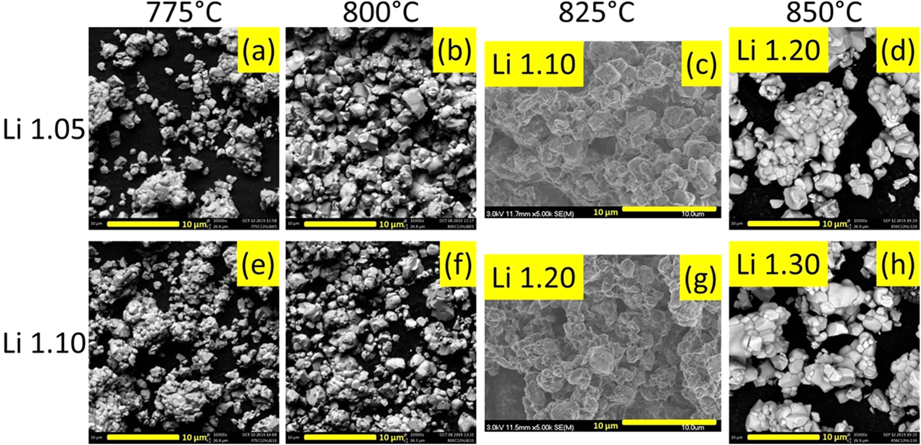
Figure 1 shows the SEM images of samples with 2.5% Mg (denoted as 2.5Mg) heated to various temperatures for 12 h. The SEM imaging of the samples heated at 825 °C was done using the Hitachi SEM due to equipment availability. The Li/TM ratios used for the samples are labelled and the images are organized so that the lower Li/TM ratio of a given temperature is in the top row (Figs. 1a–1d) and the higher Li/TM ratios are in the bottom row (Figs. 1e–h). Higher Li/TM ratios were used for higher temperatures due to concerns about Li loss. 2,4–7,13,15–18,33–39 Samples with lower Li/TM ratios were synthesized later at the higher temperatures, but no SEM imaging was done due to equipment availability from COVID-19 university closures.

Figure 1. SEM images of LiNi0.975Mg0.025O2 samples after heating for 12 h at various temperatures and Li/TM ratios.
Download figure:
Standard image High-resolution imageFigure 1 shows that heating at higher temperatures will result in larger crystallites. This is not surprising and corroborates with many previous reports. 3–10,12–18 A particle size in the micron range is desirable for SC materials. 3,5,7,8,12,15,18,22,25,40,41 The particle sizes of the samples heated at 775 °C seem to be slightly undersized and possibly the samples heated at 800 °C as well, while the samples heated to a higher temperature were suitable in size. There are no observable differences in particle size or morphology between the Li/TM ratios of 1.05 and 1.10 for 775 °C (Figs. 1a, 1e) and 800 °C (Figs. 1b, 1f), the Li/TM ratios of 1.10 and 1.20 for 825 °C (Figs. 1c, 1g) and the Li/TM ratios of 1.20 and 1.30 for 850 °C (Figs. 1d. 1h) but the impact of varying Li/TM ratios will be explored more in depth in Figs. 3 and 4.
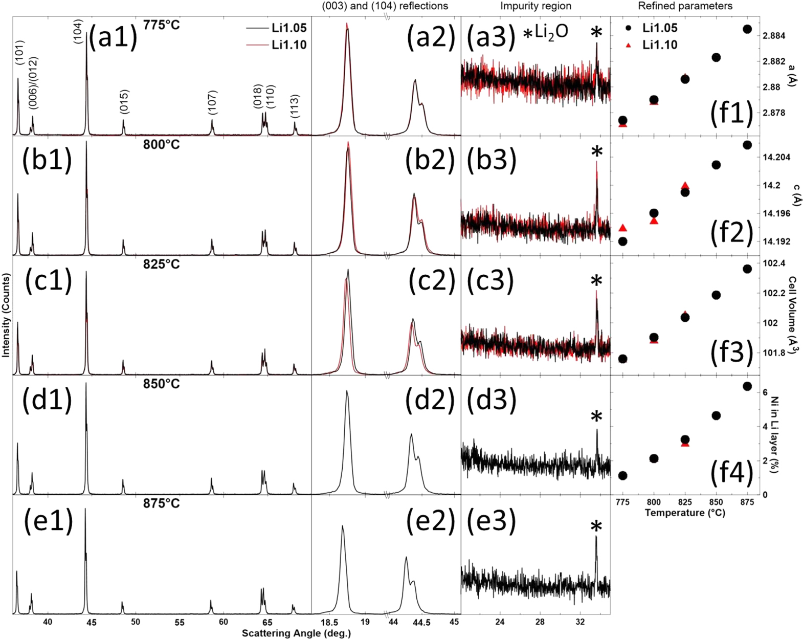
Figure 2 shows the XRD patterns of 2.5Mg samples heated to various temperatures for 12 h (Figs. 2a1–2e1). An expanded view of the (003) and the (104) reflections (Figs. 2a2–2e2), an expanded view of the impurity region (Figs. 2a3–2e3) and Rietveld refinement results (Fig. 2f1–4) are included as well. Samples with a Li/TM ratio of 1.05 are shown in black and samples with a Li/TM ratio of 1.10 are shown in red. The dominant phase in all these samples is the layered phase but a very weak peak corresponding to Li2O (JCPDS #00–077–2144; a secondary peak around 56° was also confirmed) can be observed in all the samples (Figs. 2a3–2e3).

Figure 2. XRD patterns (Cu Kα radiation) of LiNi0.975Mg0.025O2 samples after heating for 12 h at various temperatures (a)–(e) with a Li/TM ratio of 1.05 (black) or 1.10 (red). XRD patterns (a-e1) were collected from 15°−70° and expanded views of the (003) reflection (a–e2), the (104) reflection (a-e2) and the Li impurity region (a-e3) are included. Unit cell lattice constants (f1), (f2), the calculated unit cell volume (f3) and amount of Ni in the Li layers (f4) as a function of the heating temperature for the samples.
Download figure:
Standard image High-resolution imageRietveld refinement results (Figs. 2f1–2f4) show a very clear trend with increasing temperature. The individual lattice parameters, the unit cell and the Ni content in the Li layer all increase linearly with increasing temperature. This has been reported previously and corroborated in part I, 1,42 and the trend is associated with highertemperatures promoting more Ni into the Li layer and increasing the unit cell volume. The Ni content in the Li layer is just above 1% for both samples heated at 775 °C and just above 2% for both samples heated at 800 °C. Part I achieved around 2% Ni in the Li layer for micron-sized SC samples prepared at 850 °C (but only 5 h), so it seems that the one-step process may need to utilize lower temperatures than the two-step process. The challenge will be to grow particles of sufficient size while maintaining ∼2% Ni content in the Li layer.
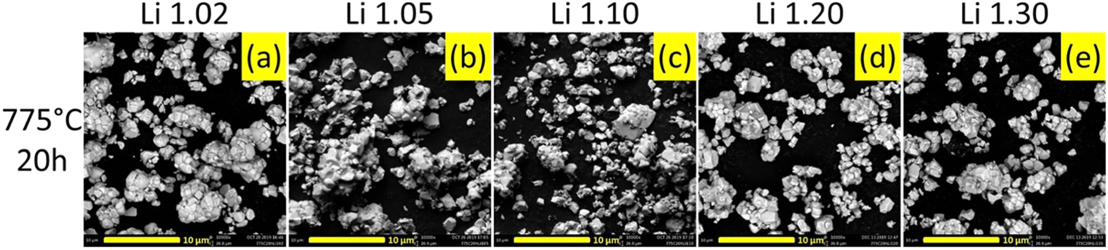
Figure 3 shows the SEM images of 2.5Mg samples heated at 775 °C for 20 h with various Li/TM ratios. The heating time was increased to see if particles could grow bigger while maintaining similar Ni content in the Li layer. Qualitatively, these samples seem to be slightly larger than the samples heated for 12 h (Figs. 1a and 1e) but still mainly in the sub-micron range. Comparing the sample with a Li/TM ratio of 1.02 and the sample with a Li/TM ratio of 1.30, there does not seem to be any significant difference in either the particle size or morphology. There may be some minor differences, but the impact of Li in this work is much smaller compared to previous reports on the importance of Li on SC particle growth. 4–13 However, studies that vary both the synthesis temperature and Li/TM ratio show that the impact of Li/TM ratio may not be significant at lower temperatures 4,5 and this seems to be the case in this work.

Figure 3. SEM images of LiNi0.975Mg0.025O2 samples after heating for 20 h at 775 °C with various Li/TM ratios.
Download figure:
Standard image High-resolution imageFigure 4 shows the XRD patterns of 2.5Mg samples heated with various Li/TM ratios (Figs. 4a1–4e1). An expanded view of the (003) and the (104) reflections (Figs. 4a2–4e2), an expanded view of the impurity region (Figs. 4a3–4e3) and Rietveld refinement results (Figs. 4f1–4f4) are included as well. Samples heated at 775 °C for 20 h are shown in black and samples heated at 800 °C for 12 h are shown in red. The dominant phase in all these samples is the layered phase but a peak corresponding to Li2O can be observed in most samples (Figs. 4a3–4e3). The sample heated at 775 °C for 20 h with a Li/TM ratio of 1.02 does not show the presence of Li2O. Figure 4 shows the impact of synthesis conditions on Li2O formation much more clearly than Fig. 2. Above a Li/TM ratio of 1.02, samples will form Li2O when heated at 775 °C for 20 h. Higher temperatures will also increase the formation of Li2O, but only below a certain Li/TM threshold as samples at a Li/TM ratio of 1.20 and 1.30 show similar amounts of Li2O for both heating regimes.

Figure 4. XRD patterns (Cu Kα radiation) of LiNi0.975Mg0.025O2 samples after heating with various Li/TM ratios (a-e) at 775 °C for 20 h (black) or 800 °C for 12 h (red). XRD patterns (a-e1) were collected from 15°−70° and expanded views of the (003) reflection (a-e2), the (104) reflection (a-e2) and the Li impurity region (a-e3) are included. Unit cell lattice constants (f1, f2), the calculated unit cell volume (f3) and amount of Ni in the Li layers (f4) as a function of the Li/TM ratio for the samples.
Download figure:
Standard image High-resolution imageRietveld refinement results (Figs. 4f1–4f4) do not show a significant trend with varying Li/TM ratios. In fact, the impact of heating temperature is highlighted once more as the samples heated at 800 °C for 12 h all have larger unit cells and more Ni in the Li layer. Unit cell parameters and volume seem to remain relatively consistent with varying Li/TM ratios. The Ni content in the Li layer seems to peak around a Li/TM ratio of 1.1, with decreasing Ni content in the Li layer as the Li/TM ratio is decreased and also as the Li/TM ratio is increased. It is unsure if this is actually a trend, but this occurs for both heating regimes.
Figures 1–4 demonstrate the impact of varying temperature and Li/TM ratios on the growth of SC materials. Increasing the temperature will increase grain growth but will also increase the Ni content in the Li layer. Increasing the Li/TM ratio does not seem to have an effect on grain growth at lower temperatures (775 °C or 800 °C) but influences the formation of the Li2O impurity. The Ni content in the Li layer may also be impacted by the Li/TM ratio. Growing particles of sufficient size while maintaining ∼2% Ni content in the Li layer will require a balancing act. Samples heated at 775 °C for 20 h with a Li/TM ratio of 1.02 were selected for further testing, as the conditions produced slightly undersized particles but hovered around 1.5% Ni in the Li layer. In terms of the Li/TM ratio, using a lower ratio minimizes Li2O formation and avoids the use of too much excess Li and could possibly avoid a potentially detrimental washing step as well. 2,5,21,31,42–47
Figures 1 and 3 show that the synthesized samples may experience grain growth but the particles are mainly aggregated in clusters. This may cause issues with connectivity to the individual particles in a cell leading to poor performance, so the aggregates should be separated. This work will report on two separation methods, one method utilizing a coffee grinder and the other utilizing a planetary mixer. A third method, sonication in various solvents (NMP, acetone, water), was tested but not reported. Sonication was able to separate aggregates very well, but all attempts resulted in reaggregation of the material after drying or evaporation of the solvent.
Figure 5 shows the SEM images of the separation tests of 2.5Mg samples heated at 775 °C for 20 h with a Li/TM ratio of 1.02. No separation (Figs. 5a1–5a2) refers to samples that were hand ground after synthesis with no extra particle separation steps. Coffee grinder (Figs. 5b1–5b2) refers to samples that were placed in a coffee grinder and ground for 6 x 30 s after hand grinding. 2 M balls (Figs. 5c1–5c2) and 20 S balls (Figs. 5d1–5d2) refer to the use of a planetary mixer utilizing 2 hardened stainless steel balls (6 mm diameter) or 20 smaller balls (3 mm diameter) and mixed for 3 × 100 s. Both milling conditions used a ∼3:1 ball:material mass ratio. Low magnification images (Figs. 5a1–5d1) and higher magnification images (Figs. 5a2–5d2) are provided so readers can get a sense of the degree of particle separation at two scales.
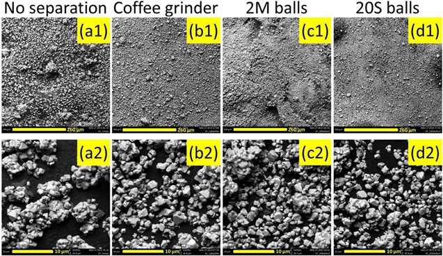
Figure 5. SEM images of LiNi0.975Mg0.025O2 samples after heating for 20 h at 775 °C with a Li/TM ratio of 1.02 and undergoing various particle separation methods.
Download figure:
Standard image High-resolution imageFigure 5 shows that the reported separation methods succeed to various degrees. Compared to no separation, the size and abundance of particle aggregates are reduced. However, all images still contained particle aggregates, so no separation method was perfect either. Qualitatively, the coffee grinder method seems to be slightly worse than the planetary mixer methods at lower magnification and similar at higher magnification.
Figure 6 shows the PSA results of the separation tests of 2.5Mg samples heated at 775 °C for 20 h with a Li/TM ratio of 1.02. Particle size distribution plots are shown on the left (Fig. 6a) and D50 values are plotted on the right (Fig. 6b). The various lines of a colour represent triplicate measurements for Fig. 6a. The 20 S balls method of separating particle aggregates is more effective than the 2 M balls method and the coffee grinder method. The D50 values suggest that PSA measurements are more indicative of the degree of particle separation rather than the particle size as Fig. 5d2 shows that single crystal grains of the 20 S balls method are smaller than the measured D50 value of >4 μm. Therefore, this method should only be taken as a semi-quantitative or even qualitative measure of the degree of particle separation, and a qualitative measure of particle size only for the same method of separation.
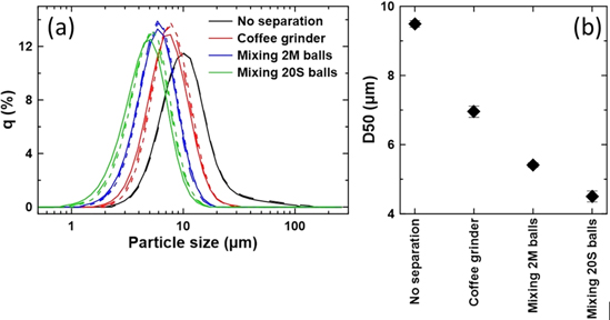
Figure 6. Particle size distribution plot (a) and D50 (b) of LiNi0.975Mg0.025O2 samples undergoing various particle separation methods.
Download figure:
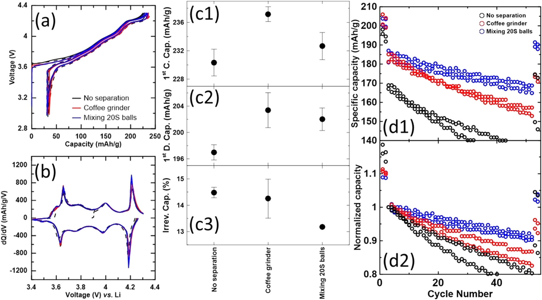
Standard image High-resolution imageFigure 7 shows the voltage (vs Li/Li+) vs specific capacity (V vs Q, Fig. 7a), the differential capacity vs voltage (dQ/dV vs V, Fig. 7b), the 1st cycle capacity data (Figs. 7c1–7c3) and the cycling performance (Figs. 7d1–7d2) for the 2.5Mg samples heated at 775 °C for 20 h with a Li/TM ratio of 1.02 and separated using different methods. Solid and dashed lines represent two duplicate cells for Figs. 7a–7b.

Figure 7. Cell voltage as a function of capacity (a) and differential capacity as a function of cell voltage (b) for the initial cycles of LiNi0.975Mg0.025O2 samples undergoing various particle separation methods. First cycle capacities by separation method (c1-c3) as well as specific capacity (d1) and normalized capacity (d2) as a function of cycle number for the samples.
Download figure:
Standard image High-resolution imageThe voltage curves (Fig. 7a) and the dQ/dV vs V curves (Fig. 7b) do not show observable differences in the electrochemical behaviour of the samples that were separated differently or not at all. This is not surprising as the base material is the same. However, there are some slight differences between the cells when looking at the capacity data (Figs. 7c1–7c3). The cells containing unseparated material have slightly lower capacity, and this can probably be attributed to the poor connectivity to individual particles due to the abundance of particle aggregates. The two separated materials have similar discharge capacities (Fig. 7c2) but the coffee ground cells have slightly higher charge capacities (Fig. 7c1). Figs. 7d1–7d2 shows that separation of particle aggregates have a significant impact on cell performance, with the cells containing unseparated material having lower capacity, worse rate retention (going from C/20 to C/5), and worse capacity retention. The cells containing coffee ground material have similar capacity, similar rate retention but worse capacity retention when compared to the cells containing the sample mixed with 20S balls. Figs. 7d1–7d2 is a clear indication that synthesized materials need to be adequately separated in order to cycle well. It may be possible that this material can cycle even better if the separation method is improved, since Figs. 5d1–5d2 shows that the particle aggregates are still present in the sample mixed with 20 S balls. Fig. 7 also suggests that the lower capacity of SC materials, when compared to PC materials, 1 do not stem from the particle aggregates since the cells with separated materials show similar capacity.
Figure 8 summarizes the Ni content in Li layer and D50 values of the 2.5Mg samples made throughout the course of this work. On the left side of the figure, the Ni content in the Li layer of the samples are plotted as a function of heating temperature (Fig. 8a) and Li/TM ratio (Fig. 8b). The D50 values are plotted as a function of heating temperature (Fig. 8c) and Li/TM ratio (Fig. 8d) on the right side of the figure. For the results plotted as a function of heating temperature, the Li/TM ratio of the sample is colour coded and the heating temperature is colour coded for the results plotted as a function of the Li/TM ratio. Not all samples were characterized by PSA and not all samples were separated when collecting the XRD pattern; XRD patterns of a few samples before and after separation has been collected and no difference was found. There were multiple synthesis conditions that varied in this summary (heating time, scale, Li source, etc) in addition to heating temperature and Li/TM ratios but the majority of the syntheses utilized similar conditions (except heating time, many samples heated at 775 °C were heated for 20 h).
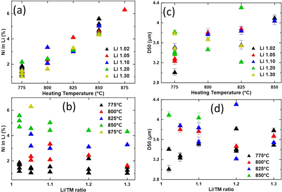
Figure 8. Amount of Ni in the Li layers as a function of heating temperature (a) and as a function of the Li/TM ratio (b). D50 as a function of heating temperature (c) and as a function of the Li/TM ratio (d).
Download figure:
Standard image High-resolution imageFigure 8a expands upon the observation from Fig. 2f4 that the Ni content in the Li layer is largely defined by the heating temperature when synthesizing SC materials and this supports previous work. 2,4–7,15–17 Part I found that this trend does not hold if grain growth is not occurring, 1 but grain growth occurs for all these samples due to the presence of sufficient Li. Compared to heating temperature, varying the Li/TM ratio (Fig. 8b) has a much smaller impact, if any, on the Ni content in the Li layers. The relationship between the D50 value and the heating temperature (Fig. 8c) is tenuous. It should be noted that the presence of particle aggregates complicates the numerical measurements as discussed in Fig. 6. Combining this weak relationship with observations from Fig. 1 suggests that heating temperature does impact grain growth and this supports previous work. 3–10,12–18 On the other hand, combining observations from Figs. 8d and 3 suggests that there is no significant impact on particle size from the amount of Li used and this does not support previous reports on the importance of Li on SC particle growth. 4–13
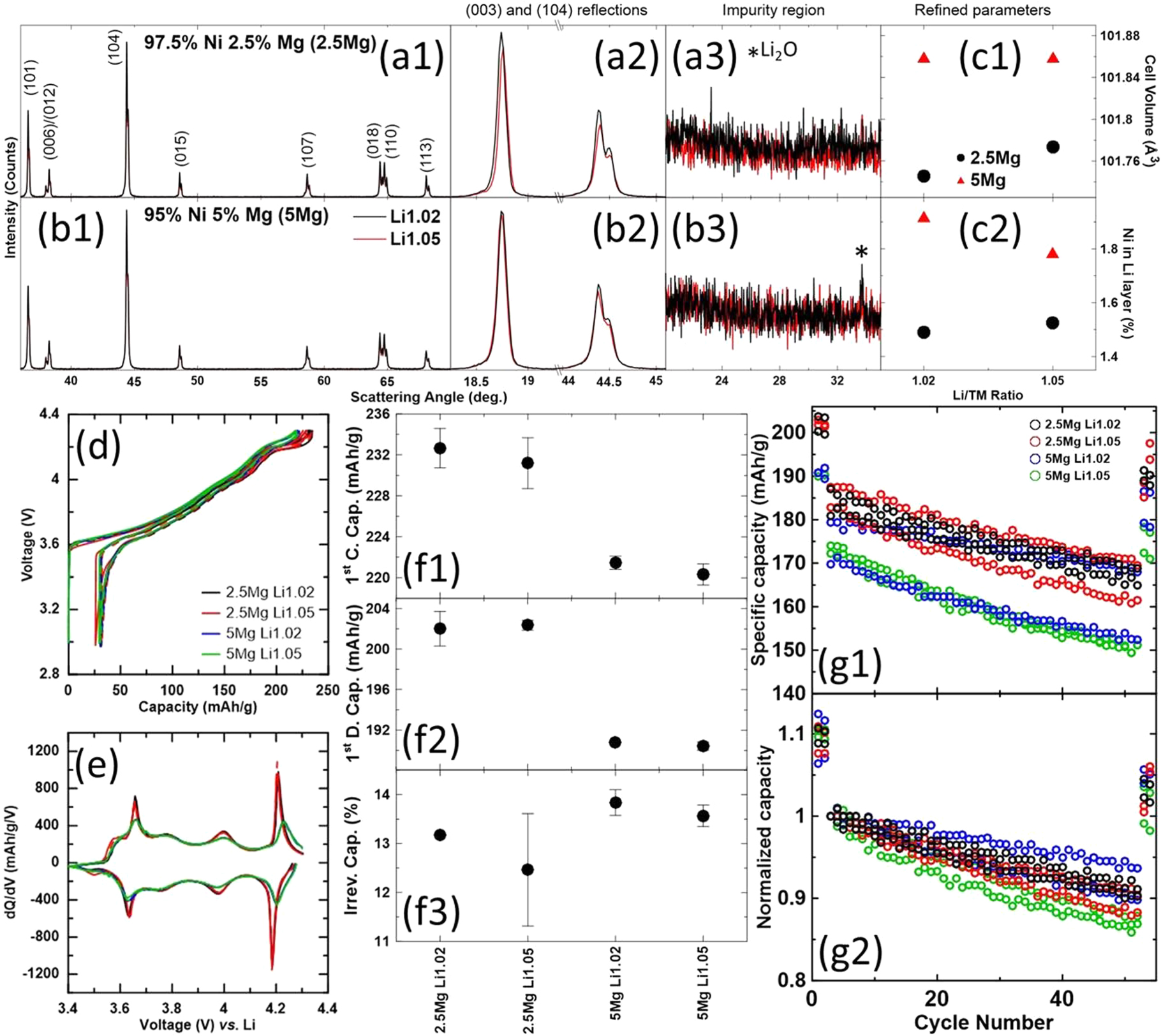
Figure 9 investigates of impact of increasing the Mg content, from 2.5% Mg (denoted as 2.5Mg) to 5% Mg (denoted as 5Mg). Figures 9a1–9b1 show the XRD patterns of the two materials, along with expanded views of the (003) reflection and the (104) reflection (Figs. 9a2–9b2), the Li impurity region (Figs. 9a3–9b3), the calculated unit cell volume (Fig. 9c1) and the amount of Ni in the Li layer (Fig. 9c2). Samples with a Li/TM ratio of 1.02 are shown in black and samples with a Li/TM ratio of 1.05 are shown in red. The V (vs Li/Li+) vs Q curves (Fig. 9d) and the dQ/dV vs V curves (Fig. 9e) of the initial cycles, the 1st cycle capacity data (Figs. 9f1–3) and the cycling performance (Figs. 9g1–2) are also shown. The XRD patterns show similar patterns for the two materials, with some Li2O formation for 2.5 Mg Li1.05 (Fig. 4b3) and 5Mg Li1.02. It is uncertain why Li2O forms on 5Mg materials with a Li/TM ratio of 1.02 but not 1.05. Refinement results show that 5Mg materials have a slightly larger unit cell and slightly more Ni in the Li layer than 2.5Mg materials, and this has been reported before in PC materials. 32

Figure 9. XRD patterns (Cu Kα radiation) of LiNi0.975Mg0.025O2 (a) and LiNi0.95Mg0.05O2 (b) samples heated at 775 °C for 20 h with a Li/TM ratio of 1.02 (black) or 1.05 (red). XRD patterns (a-b1) were collected from 15°−70° and expanded views of the (003) reflection (a-b2), the (104) reflection (a-b2) and the Li impurity region (a-b3) are included. The calculated unit cell volume (c1) and amount of Ni in the Li layers (c2) as a function of the Li/TM ratio for the samples. Cell voltage as a function of capacity (d) and differential capacity as a function of cell voltage (e) for the initial cycles of the samples. First cycle capacities by sample (f1-f3) as well as specific capacity (g1) and normalized capacity (g2) as a function of cycle number for the samples.
Download figure:
Standard image High-resolution imageFigure 9d shows that the 5Mg cells have less capacity in the initial cycles, and Fig. 9e shows that these reductions in capacity occur around 3.6 and 4.2 V, supporting previous reports. 32 Samples of both Li/TM ratios of a material have a relatively similar capacity and 5Mg cells have less capacity (Figs. 9f1–9f3). This was expected since it is known that substituting more inactive substituents results in a lower capacity. 30,32 Cycling performance results (Figs. 9g1–9g2) seem to indicate that the two materials have similar fade, but this is hard to ascertain since the 5Mg cells vary to the point where one cell cycles better and the other cell cycles worse than the 2.5Mg cells. (Fig. 9g2) For the most part, 5Mg cells generally start off with a lower capacity with no clear benefit to capacity retention (Fig. 9g1).
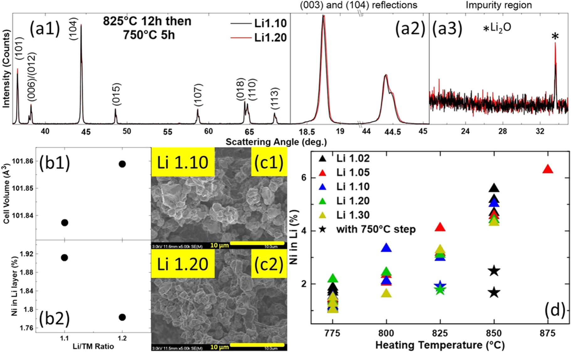
Figure 10 investigates the impact of including a lower temperature step right after the calcination step. The use of a lower temperature step after calcination has been reported to lower the Ni content in the Li layer. 17,39,48 Two-step SC syntheses also use a lower temperature to heat the 2nd step to lower the Ni in the Li layer in the process. 1,3 Although it is generally thought that the reduced Ni content in the Li layer stems from topping up the Li/TM ratio to stoichiometry, part I revealed that temperature may play a role in this process. 1 Figure 1 shows that micron-sized particles are produced by heating to 825 °C, so this was chosen as the calcination temperature and a lower temperature of 750 °C was selected due to the success in part I.

Figure 10. XRD patterns (Cu Kα radiation) of LiNi0.975Mg0.025O2 samples heated first at 825 °C for 12 h then 750 °C for 5 h with a Li/TM ratio of 1.10 (black) or 1.20 (red). XRD patterns (a1) were collected from 15°−70° and expanded views of the (003) reflection (a2), the (104) reflection (a2) and the Li impurity region (a3) are included. The calculated unit cell volume (b1) and amount of Ni in the Li layers (b2) as a function of the Li/TM ratio for the samples. SEM images of the sample with a Li/TM ratio of 1.10 (c1) and 1.20 (c2). Amount of Ni in the Li layers as a function of heating temperature (d) with the inclusion of samples that were synthesized with a 750 °C step after calcination (denoted with a star coloured by the Li/TM ratio of the final product).
Download figure:
Standard image High-resolution imageFigure 10a1 shows the XRD patterns of 2.5Mg samples heated at 825 °C for 12 h then 750 °C for 5 h, along with expanded views of the (003) reflection and the (104) reflection (Fig. 10a2) and the Li impurity region (Fig. 10a3). Samples with a Li/TM ratio of 1.10 are shown in black and samples with a Li/TM ratio of 1.20 are shown in red. The calculated unit cell volume (Fig. 10b1), the amount of Ni in the Li layer (Fig. 10b2), SEM images of the samples (Figs. 10c1–10c2) and a revised plot of Ni content in the Li layer as a function of heating temperature (Fig. 10d) are also shown in Fig. 10. Figure 10d is simply an updated plot of Fig. 8a which includes the Ni in the Li layer values for samples synthesized with a 750 °C step after calcination (denoted with a star coloured by the Li/TM ratio of the final product) from this work as well as part I. 1 Note that part I samples (the stars at 850 °C) were synthesized by heating at 850 °C for 5 h with a Li/TM ratio of 0.90 or 0.95 and taken out of the furnace, then topping off the Li/TM ratio to 1.02 and heating at 750 °C for 12 h.
As was expected from heating at 825 °C with Li/TM ratios of 1.10 and 1.20, Li2O can be observed in both samples (Fig. 10a3). The sample with a Li/TM ratio of 1.20 had slightly more Li2O, but otherwise the XRD patterns were similar. The refined Ni contents in the Li layer are under 2% (Fig. 10b2), which shows the encouraging impact of including a lower temperature step. It was reported that an annealing step promotes the reorganization of the atoms back to their respective layers but higher temperatures (> 500 °C) promote oxygen vacancies which lowers the average oxidation state of the metal atom. This would form more Ni2+ and increase the Ni content in the Li layers. 39 It is unclear why the 750 °C steps used in part I and this study were able to reorder the lattice without suffering from increased oxygen vacancies leading to more Ni in the Li layer. Further work on understanding how the low temperature step impacts the Ni content in the Li layer is needed. Comparing the values to Figs. 2f1–2f4, the unit cell volume and Ni in the Li layer values (Figs. 10b1–10b2) lie in between the samples heated at 775 °C and 800 °C, further supporting part I findings that unit cell volume is influenced more by the Ni content in the Li layer rather than by heating temperature. 1 SEM images (Figs. 10c1–10c2) show micron-sized particles (∼1–4 μm), suggesting that this synthesis method can utilize higher temperatures to grow particles while avoiding the increase in Ni content in the Li layer observed in Figs. 2f4 and 8a. The benefits of this method can be seen in Fig. 10d, where samples heated with the inclusion of a lower temperature step can reduce the Ni content in the Li layer by more than 1%.
With the advent of this new heating protocol, there are now three routes to synthesize SC materials that have around or under 2% Ni in the Li layer. The two-step method in part I first heated the precursor at 850 °C for 5 h with a Li/TM ratio less than 1 followed by a top up to a Li/TM ratio of 1.02 and heating at 750 °C for 12 h. 1 Particles were well grown, but the process requires an extra Li addition, grinding and heating step compared to the one-step process. Figures 1–4 show that heating the sample at 775 °C for 20 h with a Li/TM ratio of 1.02 can also synthesize materials with less than 2% Ni in the Li layer, but the particles are slightly undersized. Figure 10 shows that heating the sample at 825 °C for 12 h then 750 °C for 5 h may also be suitable. There seems to be fewer drawbacks to this method since the particles are well grown and the furnace can be programmed to cool to 750 °C without needing an additional grinding and heating step.
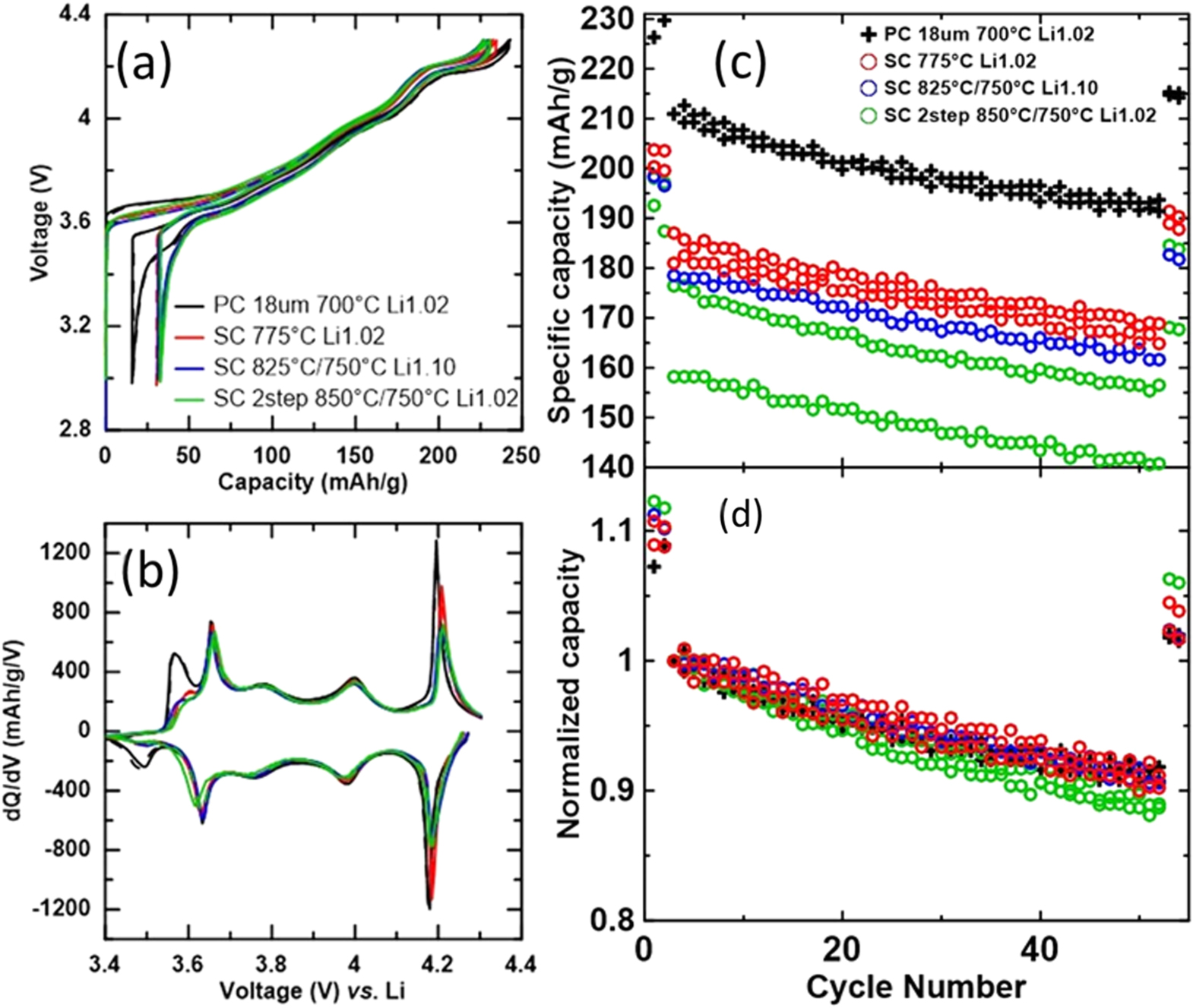
Figure 11 shows the voltage (vs Li/Li+) vs specific capacity (V vs Q, Fig. 11a), the differential capacity vs voltage (dQ/dV vs V, Fig. 11b) and the cycling performance (Figs. 11c–11d) of three SC 2.5Mg samples and a PC comparator. Solid and dashed lines represent two duplicate cells for Figs. 11a–11b. The three SC samples were synthesized by the three routes to attain around 2% Ni in the Li layer: heating the sample at 775 °C for 20 h with a Li/TM ratio of 1.02, heating the sample at 825 °C for 12 h then 750 °C for 5 h with a Li/TM ratio of 1.02, and a sample from part I heated at 850 °C for 5 h with a Li/TM ratio of 0.95 then topping up to a Li/TM ratio of 1.02 and heated at 750 °C for 12 h. 1
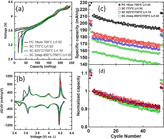
Figure 11. Comparison of the electrochemical performance of a polycrystalline (PC) LiNi0.975Mg0.025O2 material synthesized using a larger precursor size (D50 ∼ 18 μm) and single crystalline (SC) LiNi0.975Mg0.025O2 materials synthesized in this work and in part I (precursor D50 ∼ 3 μm). Cell voltage as a function of capacity (a) and differential capacity as a function of cell voltage (b) for the initial cycles of the samples. Specific capacity (c) and normalized capacity (d) as a function of cycle number for the samples.
Download figure:
Standard image High-resolution imageFigure 11a echoes the observations from part I, 1 PC materials have higher capacity and lower irreversible capacity than all SC materials tested. Once again, the reductions in specific capacity are far greater than reported for other SC materials. 3,5,9,11,12,16,21,22 A qualitative method to estimate the amount of residual Li is to look at the 1st charge voltage curve. With more residual Li, a higher voltage can be observed when the cell begins charging. 42,46 Figure 11a suggests that the poor performance of SC materials is not due to residual Li, as slightly more residual Li may be present on the PC material than the SC materials. Like part I, dQ/dV vs V curves (Fig. 11b) indicate that the capacity reductions of SC cells occur around ∼3.5 V (virtually all capacity lost) and around ∼4.2 V (some capacity lost), regions associated with kinetic hindrances of Li diffusion in the material. 23,24 Figure 11b also shows that additional capacity is lost around ∼4.2 V for the samples heated to 825 °C and 850 °C. Apart from the aforementioned differences, the dQ/dV vs V curves of the 4 samples display a very similar electrochemical behavior. Figure 11c suggests a possible trend of lower capacity with higher heating temperature, but more work is needed to confirm this observation. Figure 11d shows that all the materials have similar capacity retention, contrary to previous reports that SC materials experience less capacity fade than PC materials. 7,9,11,12,16,21,22,25–29 In part I, 1 the analysis of the dQ/dV vs V curves of PC and SC NiMg materials at the start and end of cycling suggest that the main mode of degradation for PC NiMg cells is related to structural change, specifically in the low V kinetic hindrance region. On the other hand, the structure of the SC material seems to be more stable and the main mode of degradation for SC NiMg cells seems instead to be a large increase in the polarization of the cell. Figure 11 highlights the need to understand and address the issues with these Co-free Ni-rich SC materials.
Figure 12 shows two experiments to further investigate the lower capacity of SC materials. The first experiment compared SC and PC synthesis conditions using both SC and PC precursors (D50 ∼ 3 μm and ∼18 μm, respectively). The PC synthesis conditions are heating the samples at 700 °C for 20 h with a Li/TM ratio of 1.02 and the SC synthesis conditions are the same except with a 775 °C heating temperature. The second experiment cycled SC materials at different temperature to see if the capacity could be recovered. Due to sample availability at the time of experiment, the sample tested was a suboptimal material with a Ni in the Li layer content of ∼2.5%. The V (vs Li/Li+) vs Q (Fig. 12a) and the dQ/dV vs V (Fig. 12b) of the first experiment are shown on the left side of Fig. 12 while the V (vs Li/Li+) vs Q (Fig. 12c) and the dQ/dV vs V (Fig. 12d) of the second experiment are shown on the right side. Solid and dashed lines represent two duplicate cells. The varying conditions are labelled, with the 2 digit temperatures representing the cycling temperature for the second experiment (Figs. 12c–12d).

Figure 12. Cell voltage as a function of capacity (a) and differential capacity as a function of cell voltage (b) for the the initial cycles of LiNi0.975Mg0.025O2 samples synthesized using different precursor sizes and heated to different temperatures. Cell voltage as a function of capacity (c) and differential capacity as a function of cell voltage (d) for PC and SC samples cycled at different temperatures.
Download figure:
Standard image High-resolution image
Figure 12a clearly shows that the capacity reductions stem from the use of higher heating temperatures needed to synthesize SC materials. Materials heated to 775 °C showed slightly lower charge capacities and much lower discharge capacities, resulting in higher irreversible capacities. Using smaller precursors reduced the irreversible capacity slightly, but to a smaller extent than heating temperature. Figure 12b reinforces these observations; materials heated to 775 °C have slightly smaller features ∼4.2 V during charge and almost no features ∼ 3.5 V. No effect of precursor size can be seen in the ∼4.2 V features but can be observed in the ∼3.5 V features, to a lesser extent than heating temperature again.
Figure 12c shows that cycling SC materials at 55 °C cannot recover the lower charge capacity but the discharge capacity is greatly increased, resulting in a similar irreversible capacity for SC materials cycled at 55 °C and PC materials cycled at 30 °C. The SC cells cycled at 30 °C have a discharge capacity of ∼196 mAh g−1 while cells cycled at 55 °C have a discharge capacity of ∼216 mAh g−1. Figure 12d shows that cycling at 55 °C does not affect electrochemical activity near 4.2 V but the recovered capacity stems from the ∼3.5 V region.
Numerous SC Ni-rich studies have reported a lower capacity of SC materials when compared to the PC counterpart. 3,5,9,11,12,16,21,22 SC materials with 80% or more Ni seem to corroborate with part I and this work that the capacity reductions stem mainly from a loss of capacity near 3.5 V with minor contributions from ∼4.2 V. 1,3,9,11,15 Both of these voltage regions have been associated with kinetic hindrances of Li diffusion in the material, with the hindrances being stronger at ∼3.5 V. 23,24 As materials become more Ni-rich, there is more capacity in these voltage regions, 30,32,49 so this may be why SC materials in this series report a larger capacity reduction than other SC works.
Theoretical work has shown that the dominant mechanism of Li diffusion is through divancancies and the kinetic hindrance at low states of charge (∼3.5 V) stem from the limited number of divacancies available. 24,50 SC materials likely exacerbate this kinetic hindrance due to longer Li diffusion pathways for the Li to diffuse in and out of the larger grains. Larger particle sizes would be more hindered as well, since Li needs to diffuse to and from the surfaces in contact with the electrolyte. This is observed in Fig. 12b, with both SC materials and larger particle sizes showing less capacity in the ∼3.5 V region. Cycling at higher temperatures would facilitate vacancy migration and increase the frequency of divacancies, lowering the kinetic hindrance. This explains the recovered capacity in Figs. 12c–12d which has been observed in previous reports on PC Ni-rich materials as well. 23,30 The kinetic hindrance at high states of charge (∼4.2 V) has been attributed to the collapse of the interlayer spacing as Li layers are emptied. 24 SC materials may experience more kinetic hindrance at this region due to larger primary particle sizes which amplify the effects of the reduction in Li diffusion constant which occurs at high states of charge. The interlayer spacing is heavily dependent on the Li content of the material, 30,31,51 so it may be possible that temperature does not have a significant effect on Li diffusion at this voltage region as observed in Fig. 12d.
Conclusions
This work studied the synthesis of Co-free single crystalline Mg-doped LNO using a one-step lithiation method. Higher heating temperatures promoted grain growth, but also increased the Ni content in the Li layer. Increasing the Li/TM ratio does not seem to have an effect on grain growth at lower temperatures (775 °C or 800 °C) but influences the formation of Li2O impurity. The separation of particle aggregates is required to improve the cycling performance of the material. Materials with a higher Mg content have less capacity with no clear benefit to capacity retention. The utilization of a lower temperature step after the calcination step can reduce the Ni content in the Li layer below what would be expected at the calcination temperature, and this can be used to grow larger grains while keeping an acceptable amount of Ni in the Li layer. However, all Mg-containing SC materials tested are still not yet competitive with PC materials and have lower capacities, higher irreversible capacities, and similar cycling fade. The lower capacities of SC materials stem from increased kinetic hindrances to Li diffusion at ∼3.5 V and ∼4.2 V compared to PC materials. The SC cells cycled at 55 °C can recover ∼20 mAh g−1 of discharge capacity and have similar irreversible capacity compared with PC cells cycled at 30 °C.
Acknowledgments
The authors would like to acknowledge NSERC and Tesla Canada for funding this work under the auspices of the Industrial Research Chair program. AL thanks the Walter C. Sumner Foundation for financial support. NZ thanks the China Scholarship Council for financial support. HL thanks the Nova Scotia Graduate Scholarship program for financial support. The authors thank Yiqiao Wang, Shuo Yin and Haohan Wu of Zoomwe for providing the precursors used in this work.