
Abstract
Cation mixing in Li-based layered positive electrode materials has been reported to negatively affect the electrochemical performance and transport properties of intercalated Li. However, no previous reports have systematically correlated the impact of cation mixing (Ni atoms in the Li layer) on the electrochemical properties and Li transport. Herein, a series of Li-deficient LNO (Li1−xNi1+xO2) materials with different amounts of Ni in the Li layers ranging from ca. 1.5%–6.0% was intentionally prepared by varying the Li/Ni ratio during synthesis. An order of magnitude decrease in the Li chemical diffusion coefficient was found between samples with 1.5% and 6% Ni in the Li layer. A similar dependence of the diffusion constant on the amount of Ni in the Li layer was also observed in the Li-excess materials  for x = 0, 0.04, 0.08, 0.12, suggesting that, in general, larger amounts of Ni in the Li layer will lead to worse kinetics. This work quantitatively demonstrates that the amount of Ni in the Li layer needs to be carefully considered for the development of high-energy Ni-containing layered positive electrode materials as it directly affects overall electrochemical performance, phase transitions, and Li diffusion, leading to worse kinetics and seriously hindering rate capability.
Export citation and abstract BibTeX RIS

This is an open access article distributed under the terms of the Creative Commons Attribution 4.0 License (CC BY, http://creativecommons.org/licenses/by/4.0/), which permits unrestricted reuse of the work in any medium, provided the original work is properly cited.
Li-ion batteries (LIBs) with high energy density, low cost, and long cycle life hold the promise of wide-spread electric vehicle adoption and large-scale grid storage applications. Layered positive electrode materials, especially Ni-containing ones such as LiNi1−x−yMnxCoyO2 (NMC) and LiNi1−x−yCoxAlyO2 (NCA), are desired due to their reasonable cost and high theoretical specific capacity of up to 270 mAh g−1. However, such high specific capacities are not normally achieved. One key factor that directly controls the reversible capacity, rate capability, and energy/power density of these materials is the transport of Li ions. 1,2
In Li-based layered positive electrode materials, the dominant diffusion pathway is the so-called divacancy hopping where Li ions hop between octahedral sites in the Li layer through an intermediate tetrahedral site. 3 However, for Ni-containing positive electrode materials, cation mixing; where Ni2+ ions occupy octahedral sites in the Li layer, takes place due to the small difference in ionic radii between Li+ (0.76 Å) and Ni2+ (0.69 Å) and the relative instability of Ni3+ at high temperature (i.e. during synthesis). 4,5 The Ni2+ ions located in the Li layers are expected to disturb the Li diffusion/kinetics due to the decrease in inter-slab thickness due to shorter Ni–O bond lengths compared to Li–O, affecting the rate capability. Since the Ni2+ ions occupy lithium sites, the reversible specific capacity is also reduced. The degree of cation mixing may also be enhanced during cycling causing surface reconstruction to a rock salt-like structure with even slower Li diffusion. 6
Arai et al. reported a series of Li1−xNi1+xO2 samples where x = 0.005–0.135 and their electrochemical performances. 7 Samples with larger x values (more Ni atoms in the Li layer) showed larger polarizations and smaller reversible capacities. Delmas et al. also reported the electrochemical performances of a similar set of materials (Li1−xNi1+xO2 where x = 0.02–0.24). 5,8 It was postulated that when a large fraction of the available Li was de-intercalated, the Ni2+ ions in the Li layer oxidized to Ni3+ (ionic radii = 0.56 Å) decreasing the inter-slab spacing and increasing electrostatic repulsion, making Li sites in the vicinity difficult to intercalate. Ceder et al., through ab initio computations, predicted an increase in activation barrier for Li migration as a result of decreased Li-layer spacing. 9,10 Even though cation mixing has previously been shown to affect the electrochemical performance of LIBs, no direct measurements of Li diffusion as a function of the amount of cation mixing (Ni in the Li layer) have been made to our knowledge.
To measure the Li chemical diffusion coefficient as a function of state of charge, the Galvanostatic and Potentiostatic intermittent titration techniques (GITT and PITT) are extensively used. 11,12 However, a broad range of apparent chemical diffusion coefficients have been obtained from such techniques, varying over several orders of magnitude for identical materials. The uncertainties stem from different experimental conditions and assumptions such as the determination of active surface area, Li diffusion lengths, and molar volume of lithiated material. 13,14 Therefore, a more effective and careful diffusion measurement needs to be developed as it will be essential for the characterization and development of advanced positive electrode materials for high-energy LIBs, especially as the Ni content is increased and cells are cycled to higher voltages—two directions positive electrode materials are being pushed in order to lower cost and increase energy density. Measurements of Li diffusion with fewer variable parameters, better repeatability, and consistent comparison across varying particle morphology would prove valuable for characterizing the influence of cation mixing on Li kinetics.
Herein, the "Atlung method for intercalant diffusion" (AMID), recently developed by our group, 15 was used to systematically investigate Li diffusion as a function of the amount of Ni in the Li layers. This method requires the average particle size as a sole fitting parameter. Whether to select the primary particle size, the secondary particle size, or an intermediate value of typical NMC or NCA materials, requires careful consideration. The accessible capacity obtained during potential steps at various voltages was used to determine the chemical diffusion coefficient of Li ions, Dc as a function of voltage. Li-deficient LNO materials with different amounts of Ni in the Li layer (Li1−xNi1+xO2, 0 ≤ x ≤0.06) were purposely prepared and chosen as representative of layered Ni-rich positive electrode materials with varying amounts of Ni atoms in the Li layer. The correlations between the amount of Ni in the Li layer, electrochemical performance and chemical diffusion coefficient of Li ions were systematically studied.
Experimental
Chemicals and materials
Reagents used for the synthesis of cathode materials included 15 μm Ni(OH)2 precursor (Zoomwe Zhengyuan Advanced Material Co., Ltd.), 16 μm Ni0.5Mn0.5(OH)2 precursor (Zoomwe Zhengyuan Advanced Material Co., Ltd.), Li2CO3 (99%, Alfa Aesar), and LiOH·H2O (99%, Nemaska). Reagents used for preparing the electrolyte included lithium hexafluorophosphate (LiPF6, Shenzhen Capchem, 99.9%), fluoroethylene carbonate (FEC, Shenzhen Capchem, 99.94%), ethylene carbonate (EC, Shenzhen Capchem, 99.5%), and dimethyl carbonate (DMC, Shenzhen Capchem, 99.95%).
Synthesis of Li-deficient LNO
The Li-deficient LNO materials were synthesized by mixing the Ni(OH)2 precursor with a lithium source; LiOH·H2O with varying Li:Ni ratios from 0.88–1.02. The powders were ground together with a mortar and pestle until homogeneous. The material was placed in an alumina ceramic boat and heated in a tube furnace in an oxygen atmosphere for 3 h at 480 °C, removed, and ground again. It was then heated for 2 h at 480 °C and then for 20 h at 700 °C. A heating rate of 10 °C min−1, along with a gas flow of 60 sccm (a 50 mm diameter furnace tube was used) was used in both heating steps. The powder was removed after the final heating step and ground once more before cell production and analysis. The powder was stored in an argon atmosphere.
Synthesis of Li1+x(Ni0.5Mn0.5)1−xO2
The  materials were synthesized by mixing of Ni0.5Mn0.5(OH)2 precursor with Li2CO3 with x = 0, 0.04, 0.08, and 0.12 with a mortar and a pestle. The material was heated to a temperature of 1000 °C for 10 h with a heating rate of 10 °C min−1 under air in a box furnace. After the heating process, the furnace was naturally cooled to room temperature and the materials were ground again before characterization and electrode fabrication.
X-ray diffraction (XRD)
A Bruker D8 diffractometer with a Cu Kα
X-ray source and a diffracted beam monochromator was used to analyze the synthesized powders. The powder was pressed in a sample holder and scanned with a scattering angle (2θ) from 15–70° with a 0.02° increment step and a dwell time of 3 s. Rietveld refinement was completed on the powder patterns with Rietica software to determine lattice constants and amount of Ni in the Li layer in each of the samples. For the Li1−xNi1+xO2 samples a R-3m space group was used in refinement and lithium and excess Ni were assumed to be at the 3a sites, nickel at the 3b sites, and oxygen at the 6c sites. Constraints in which Ni (in 3b) and Li (in 3a) can be exchanged with a fixed stoichiometry were applied to determine the amount of Ni in the Li layers. For the  samples, cation mixing between the Li layers and the transition metal layers was allowed subject to the constraint that the overall stoichiometry was maintained.
Scanning electron microscopy (SEM)
A NanoScience Phenom Pro G2 Desktop Scanning Electron Microscope was utilized to image the synthesized powders with an accelerating voltage of 5 kV and an emission current of 0.6 nA. Samples were prepared for imaging by sticking the powders to a sample stub with a conductive graphite tape.
Coin cells
For electrochemical measurements and cycling tests, the electrode sheets were prepared by mixing active material, polyvinylidene difluoride (PVDF, Kynar 301 F), and carbon black (SuperS, Timcal) in a weight ratio of 92:4:4 in N-methyl-2-pyrrolidone (NMP, 99.5% Sigma-Aldrich). The slurry was cast onto aluminum foil using a 150 μm notch-bar spreader and then dried at 120 °C for 3 h. The dried electrodes were pressed at a pressure of 2000 atm and then punched into discs with an area of 1.2 cm2. The active material loading was ∼10 mg cm−2. Prior to coin-cell fabrication, the electrodes were vacuum-dried at 120 °C overnight. The electrolyte used was 1.2 M LiPF6 in FEC:DMC (1:4 vol/vol). Coin-cells were assembled with two layers of Celgard-2300 separators and Li metal was used as a negative electrode. Charge-discharge cycling was performed at 30 °C using an E-one Moli Energy Canada battery testing system. The cells were tested using a voltage window of 3.0–4.3 V vs Li+/Li at a C/20 (1C = 200 mA g−1) for the first two cycles, followed by C/5 for 20 cycles and finally C/20 for the last two cycles. For Li-ion diffusion measurement, the composition of active material: PVDF: SuperS was 84:8:8. A 40 μm notch-bar spreader was used which yielded an active mass loading of ∼0.8–1.0 mg cm−2. The loadings were purposely made very low so that Li-ion transport in the electrolyte would not affect the electrochemical measurements needed to determine Dc . The cells were assembled using 1.2 M LiPF6 in EC:DMC (1:1 vol/vol) with one layer of Celgard separator. The electrode composition, active mass loading, electrolyte composition, and separator thickness were selected to minimize internal resistance (IR) of the cell during the diffusion measurement. An in-depth study on AMID optimization will be published in future work. 16
Atlung method for intercalant diffusion (AMID)
The cells were tested using a voltage window of 3.0–4.3 V vs Li+/Li at C/20 for the first cycle, then charged to 4.3 V vs Li+/Li at C/40. The next discharge was performed with successive C-rates of 5C, 3C, 2C, 1C, C/2.5, C/5, C/10, C/20, C/40, C/80, and C/160, with 1 h OCV between each C-rate, from 4.3 to 3.6 V vs Li+/Li in 0.1 V intervals, and from 3.6–3.0 V vs Li+/Li in a single interval. The cells were finally charged back to 4.3 V vs Li+/Li at C/40. The measurements were performed at 20 °C, 30 °C, and 40 °C using an Ultra-high precision charging system (UHPC). 17,18
Results and Discussion
Figure 1 displays the SEM images of the synthesized powders with different Li/Ni ratios. All samples showed a typical spherical morphology of agglomerated primary particles with similar secondary particle sizes of ∼13 μm. Varying the Li/Ni ratio did not affect the particle size or morphology of the samples after the lithiation process. Higher resolution images, shown in Fig. 2 for selected samples, show that the average primary particle size was between 0.2−0.25 μm for all the samples measured. The secondary and primary particle sizes will be used later for measurements of Li chemical diffusion coefficients.

Figure 1. SEM images of Li-deficient LNO samples synthesized with varying Li/Ni ratios to control the amount of Ni in the Li layer (a)–(e) and a typical Li/Ni ratio used for LNO synthesis (g).
Download figure:
Standard image High-resolution image
Figure 2. High-resolution SEM images of many primary particles within a single secondary particle of Li-deficient materials with Li/Ni ratios during synthesis of 0.88 (a), 0.92 (b), 0.96 (c), and 1.02 (d). The primary particle size calculated using the ImageJ software is shown.
Download figure:
Standard image High-resolution imageFigure 3 shows the full XRD patterns and two expanded views for the entire series of synthesized materials. All samples were single phases with well-developed layered structures. No impurities were observed in the samples as seen from a lack of peaks in the lithium impurity region between 20–35 degrees. The peaks became sharper with clearer Kα1 and Kα2 doublets when increasing the Li/Ni ratio as can be seen from the expanded views of the (104) peak between 44o–45o and the (018)/(110) peaks between 64o–65.5o. This indicates a greater degree of crystallinity in the samples with higher Li/Ni ratio as the stoichiometric chemical composition is approached. Overall, this represents a set of highly crystalline materials with similar morphologies well-suited for comparisons of electrochemical and kinetic properties.

Figure 3. The XRD patterns of Li-deficient LNO samples from 0.88–1.02 li/Ni (a–g). Fitted data (red) and difference plots (green) show good agreement with the measured data (black points).
Download figure:
Standard image High-resolution imageFigure 4a shows the relationship between the expected and observed percentage of Ni atoms in the Li layers (%NiLi) for the various Li-deficient LNO powders. Expected values were calculated based on the amounts of Li and Ni used in the lithiation and charge balance. As the Li/Ni ratio is decreased during synthesis, the %NiLi is expected to increase linearly; the excess Ni is expected to assume a 2+ oxidation state, favorably occupying sites in the Li layers. The observed %NiLi values were close to the expected values except at high Li/Ni ratios, which is not surprising since there is always between ∼1%–2%NiLi even under Li-excess synthesis conditions (off-stoichiometry). To our knowledge, a pure two-dimensional structure with no Ni atoms in the Li layers has never been achieved with LNO. Similarly, in Fig. 3b, as the observed %NiLi increases, both the a and c lattice parameters increase due to the presence of Ni2+ ions in both Li and Ni layers; for each Ni2+ in the Li layer there must be one Ni2+ in the Ni layer to maintain charge neutrality. Since the Ni2+–O bond length is slightly longer compared to the Ni3+–O bond length, the average unit cell size is increased in all 3 directions. All the parameters used and obtained from Rietveld refinement are summarized in Table I.

Figure 4. Percentage of Ni atoms in the Li layers as a function of Li/Ni ratio (a) and lattice parameters of the hexagonal unit cell as a function of the percentage of Ni atoms in the Li layers (b) for the series of Li-deficient LNO samples.
Download figure:
Standard image High-resolution imageTable I. Lattice parameters from Rietveld refinement of all samples.
| Li/Ni Ratio | y in Li1−yNi1+yO2 | a (Å) | c (Å) | Ni in Li layer (%) | RB |
|---|---|---|---|---|---|
| 0.88 | 0.0638 | 2.8819 | 14.207 | 5.829 | 1.36 |
| 0.90 | 0.0526 | 2.8809 | 14.204 | 5.518 | 1.59 |
| 0.92 | 0.0417 | 2.8797 | 14.200 | 4.264 | 1.35 |
| 0.94 | 0.0309 | 2.8785 | 14.202 | 2.936 | 1.58 |
| 0.96 | 0.0204 | 2.8782 | 14.201 | 2.483 | 1.53 |
| 0.98 | 0.0101 | 2.8774 | 14.193 | 1.868 | 2.06 |
| 1.02 | 0 | 2.8759 | 14.187 | 1.498 | 1.92 |
Figure 5 shows the 1st and 2nd cycle voltage vs specific capacity profiles for each Li-deficient LNO material compared to standard LNO (Li/Ni = 1.02) at C/20 between 3.0–4.3 V vs Li+/Li. The cells with greater Li/Ni ratios (smaller %NiLi) showed larger charge and discharge specific capacities and lower irreversible specific capacities (IRC) compared to the cells with smaller Li/Ni ratios (larger %NiLi). The clear plateaus and steps, representing phase transitions and single-phase regions, can be clearly seen in the higher Li/Ni ratio cells suggesting that the materials undergo Li insertion/extraction with faster Li diffusion, thus less kinetic hindrance. The impact of the %NiLi on the Li chemical diffusion, which is the main objective of this work, will be discussed in relation to Figs. 9–13.

Figure 5. 1st (solid-line) and 2nd (dash-line) cycle charge-discharge profiles at C/20 of Li-deficient LNO (red, a–f) and standard LNO (black) samples tested at 30 °C.
Download figure:
Standard image High-resolution imageTo understand the electrochemical reactions, the differential capacity vs voltage (dQ/dV vs V) during the 1st discharge and 2nd charge is shown in Fig. 6. The LNO cell showed typical phase transitions including hexagonal to monoclinic (H1 → M), monoclinic to hexagonal (M → H2), and hexagonal to hexagonal (H2 → H3), respectively. 19 The region below 3.6 V vs Li+/Li is often referred to as the kinetic hindrance (KH) region since the suppression of the dQ/dV peak has been shown to be caused by kinetic hindrance and can be recovered, in most cases, by cycling at higher temperature or lower rates. 15,20 It is clearly seen that as more Ni atoms were added into the Li layers (smaller Li/Ni ratios), the kinetic hindrance peaks were gradually suppressed, suggesting that the presence of NiLi impacts the kinetic properties of the material. In general, all the peaks became less intense and broader, especially the H2 → H3 phase transition peak. This suggests that there was no abrupt layer shrinkage, typically observed in the presence of the H3 phase, possibly because of the presence of randomly substitutive Ni atoms in the Li layers that serve as pillars and prevents Li ordering, thus suppressing the H2 → H3 and other phase transitions. 7,21

Figure 6. Differential capacity vs voltage measured at C/20 of Li-deficient LNO (red, 1–f) and standard LNO samples (black).
Download figure:
Standard image High-resolution imageFigure 7a shows the cycling performance of all samples at C/5 after the first two cycles at C/20. Standard LNO (Li/Ni 1.02) showed the largest specific discharge capacity as compared to the Li-deficient samples where the capacities decreased as the Li/Ni ratios decreased (%NiLi increased). The existence of extra Ni2+ in the Li layers requires the presence of2x Ni2+ and (1−x) Ni3+ ions in the overall structure to maintain electroneutrality according to the Li1−xNix 2+[Ni1−x 3+Nix 2+]O2 formula. This reduces the amount of electrochemically active Ni3+ available during charge/discharge. 22 There was little variation in capacity retention for all stoichiometries after 20 cycles despite the suppression of the H2–H3 phase transition in the samples with lower Li/Ni ratios, which is believed to be a major cause of poor capacity retention. 23 Longer-term cycling and material characterization would provide useful insight into the capacity fade mechanisms in Li-deficient materials and more generally in materials with a larger %NiLi. Figure 7b shows the 1st cycle IRC at C/20 and the %NiLi as a function of Li/Ni ratio. The %NiLi and 1st cycle IRC follow very similar, near-linear trends, suggesting a strong correlation. Taken together with the capacity-rate dependence illustrated in Fig. 7a (the difference between C/20 and C/5 capacities), it is clear that the %NiLi strongly influences Li kinetics.

Figure 7. Discharge capacity retention at C/5 and 30 °C (3.0–4.3 V) (a) and 1st cycle IRC and percentage of Ni atoms in the Li layers as a function of Li/TM ratio (b) of Li-deficient LNO samples.
Download figure:
Standard image High-resolution imageFigures 8a and 8b show voltage vs time and voltage vs specific capacity from an AMID measurement. The cells were first charged and discharged at C/20 for 1 cycle followed by a C/40 charge. Sequential discharge currents as in the "signature curve method" 24 ranging from 5C to C/160 with 1 h relaxation periods (OCV) in between were then applied in 0.1 V intervals from 4.3 to 3.6 V and in one voltage step for the KH region between 3.6–3.0 V. A larger voltage interval was chosen for the KH region because of the small amount of available capacity below 3.5 V, especially in the cells with smaller Li/Ni ratios. The cells were then charged back to 4.3 V at C/40. Figure 8b shows that there was no capacity slippage when the cell was charged back to 4.3 V after the AMID measurement. This confirms that there were no negative effects nor degradation of the active materials and that the capacities measured during the AMID cycle were real and not an artefact of side-reactions (i.e., electrolyte oxidation, capacitive effects, etc.). This indicates the importance of UHPC to accurately measure data over more than two orders of magnitude in C-rate to have confidence in the measurements.

Figure 8. Atlung Method for Intercalant Diffusion (AMID): Voltage vs Time (a), Voltage vs Capacity (b), example of a "signature curve" for a 3.6–3.0 V interval (c), cumulative capacity vs C-rate (d), and fitted capacity-rate data plotted on top of the theoretical curve from Ref. 21 (e). Black and red colors represent two duplicate cells.
Download figure:
Standard image High-resolution imageFigure 8c shows an example "signature curve" for the 3.6–3.0 V interval. "Signature curves" are a way of achieving specific states of charge corresponding to a given voltage in substantially less time compared to using one single very small current (to minimize kinetic effects). The cumulative capacity achieved when discharging to a specific voltage cut-off by sequentially lowering the current with intermittent open-circuit periods has been shown to be nearly identical to the capacity achieved using a single discharge with the smallest current used in the sequence. 24 The protocol C-rates used for the AMID measurements were calculated based on the full theoretical capacity of the materials over the entire voltage range (3.0–4.3 V). However, since the AMID measurement involves discharging within specific voltage intervals each with different available capacities, effective rates are calculated as the total capacity achieved in a given voltage interval after the "signature curve" (sequence of discharge currents) divided by each respective current. Figure 8d shows the cumulative capacity extracted from each discharge current for the corresponding 3.6–3.0 V interval. The curve in Fig. 8d begins to plateau at low rates (far right) but is not exactly flat, suggesting that more capacity may have been extracted if even lower rates were used. This, of course, means that in cases where the capacity-rate curve does not fully plateau, the effective rates are not exact. In general, the capacity-rate curves showed a nice plateau at low rates, thus the effective rates are a good representation of the load on the cell.
To determine the voltage-dependent diffusion coefficient from the "signature curves," the capacity-rate data for each voltage interval is fit with a least-squares optimization to the solution derived by Atlung et al. 25 to describe electrochemical insertion (or extraction) for spherical particles. Equation 1 is modified from Ref. 25 to include the discharge time and the possibility that the full available capacity may not have been extracted during a particular "signature curve" for a given voltage interval. Figure 8e shows the fitted experimental data (circles) on top of the theoretical curve developed by Atlung et al. on a dimensionless scale. The capacity-rate data from a "signature curve" for a given voltage interval, of the form (c in mAh, n in C/n), is fit to Eq. 1 treating both Dc and cmax as fitting parameters. The fractional capacity, c/cmax, is plotted against the dimensionless variable, Q = 3600 nDc r−2, which is the ratio of the discharge time, 3600 n, and the diffusion time, r2/Dc (r is the particle radius, thus r2/Dc is the characteristic time needed for a diffusing species to get from the surface to the center of a particle). A, B, and αi are geometric factors, where for spherical particles A = 3, B = 5, and αi cot (αi ) = 1. The expansion included αi up to i = 158 as this was found to be well-converged down to Q = 0.001. It is important to recognize that Eq. 1 is a solution to the phenomenological diffusion equations from Fick's Laws. Capacity-rate data extracted from a "signature curve" for a given voltage interval (it could be 4.3–4.2 V, or 4.0–3.6 V, for example) is numerically fit to Eq. 1 to extract Dc , which is an average quantity over the particular voltage interval. Examples of curve fittings and summary graphs showing quality of fit metrics for all samples are shown in Figs. S1–S9 (available online at stacks.iop.org/JES/168/090535/mmedia). Fine-grained details of the fitting procedure are given in Ref. 15.
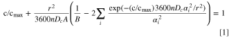
Figure 9 shows Dc as a function of discharge voltage for samples with Li/Ni ratios ranging from 0.88 to 1.02 obtained from the AMID measurements at temperatures of 20, 30, and 40 °C. To obtain the results in Fig. 9, a sphere radius, r, of 6.5 μm, characteristic of the secondary particle radius was used. Figure 10 shows Dc for the same experiments but where the primary particle radii, r, used in the fitting procedure were taken from the high-resolution SEM images shown in Fig. 2. A discussion is presented later to address whether using primary or secondary particle radii is most appropriate to use for this calculation. Dc for all samples increased as the operating temperature increased as is expected from classical diffusion theory. The samples with larger Li/Ni ratios (smaller %NiLi) showed larger Dc across the entire voltage range for all 3 temperatures with the only exceptions being the 3.0–3.6 V, and 3.6–3.7 V intervals at 20 °C. The dependence of Dc on the %NiLi is still clearly seen at 20 °C between 3.7–4.2 V. The data point for the 4.2–4.3 V interval is omitted in Fig. 9a (20 °C) because a large IR drop with very little cumulative capacity was measured in this interval, causing error in the calculation of effective rates and poor fits. These difficulties were not encountered for the 30 and 40 °C measurements (Figs. 9b, 9c, 10b and 10c).

Figure 9. Chemical diffusion coefficient of Li ions, Dc , obtained using secondary particle radii, as a function of voltage at 20 °C (a), 30 °C (b), 40 °C (c) of Li-deficient LNO samples synthesized with Li/Ni ratios ranging from 0.88 to 1.02.
Download figure:
Standard image High-resolution image
Figure 10. Chemical diffusion coefficient of Li ions, Dc , obtained using primary particle radii, as a function of voltage at 20 °C (a), 30 °C (b), and 40 °C (d) for Li-deficient LNO samples synthesized with Li/Ni ratios ranging from 0.88 to 1.02.
Download figure:
Standard image High-resolution imageAt all temperatures Dc was largest between 3.7–4.0 V when the interlayer spacing remained sufficiently large, maintaining the moderate Li tetrahedral site energy, while the Li concentration was sufficiently small to accommodate non-dilute di-vacancies. In the low voltage KH region (the 3.3 V data point), the %NiLi barely influences Dc . At such low voltages, the Li layers are nearly full and the di-vacancy concentration approaches zero, severely hindering Li diffusion. 26 It is interesting that diffusion is already so slow below 3.6 V that the %NiLi has such little impact. Dc also becomes small beyond 4.2 V; the interlayer space is contracted as the Li layers are depleted, increasing the tetrahedral Li site energy due to coulombic repulsion from Ni atoms in the TM layer. 2
The data from Figs. 9 and 10 are re-plotted in Figs. 11 and 12 to show Dc as a function of %NiLi for voltages between 3.6–4.2 V and at 20, 30, 40 °C. Showing the data in this way, the impact of %NiLi on Dc is striking—in the 3.7–4.1 V interval, containing ∼80% of the total cell capacity, Dc decreases by an order of magnitude as the %NiLi goes from 2 to 6%. A 4% increase in the %NiLi leads to an order of magnitude decrease in Dc . In general, this trend is similar regardless of the temperature and regardless of the choice of secondary (Figs. 9 and 11) or primary (Figs. 10 and 12) particle radius. This fact alone explains the large increase in 1st cycle IRC observed in Fig. 7 as the %NiLi increased from 2%–6% and attributes the cause to poor Li kinetics. Figures 11a, 12a, 11f and 12f show a less pronounced decrease in Dc as the %NiLi increases. Dc below 3.6 V is not shown in Figs. 11 and 12 since the impact of the %NiLi is much less prominent due to Li kinetics already being so poor. These results demonstrate that the %NiLi can have a significant impact on the rate capability and reversible capacity of Ni-rich layered positive electrode materials, and perhaps more generally, any intercalation electrode with a non-negligible amount of cation mixing. As a result, one must keep the amount of Ni atoms in the Li layers as low as possible in order to maximize Dc for good rate capability and optimized electrochemical performance.

Figure 11. Chemical diffusion coefficient of Li ions, Dc , obtained using secondary particle radii, as a function of the percentage of Ni atoms in the Li layers for the 4.2–4.1 V (a) 4.1–4.0 V (b) 4.0–3.9 V (c) 3.9–3.8 V (d) 3.8–3.7 V (e) 3.7–3.6 V (f) intervals and at 20 °C (blue), 30 °C (black), and 40 °C (red).
Download figure:
Standard image High-resolution image
Figure 12. Chemical diffusion coefficient of Li ions, Dc , obtained using primary particle radii, as a function of the percentage of Ni atoms in the Li layers for the 4.2–4.1 V (a) 4.1–4.0 V (b) 4.0–3.9 V (c) 3.9–3.8 V (d) 3.8–3.7 V (e) 3.7–3.6 V (f) intervals and at 20 °C (blue), 30 °C (black), and 40 °C (red).
Download figure:
Standard image High-resolution imageIn the present work, whether the primary or secondary particle radius was chosen to fit the capacity-rate data obtained from the AMID measurements was inconsequential; the same qualitative trend was observed in both cases. However, since the primary particles were about 2 orders of magnitude smaller than the secondary particles (13 μm compared to 0.2 μm), the fitted magnitudes of Dc
differed by nearly 4 orders of magnitude (Dc
scales as 1/r2). Additionally, all samples studied in this work had very similar primary and secondary particle sizes. The materials with smaller Li/Ni ratios (larger %NiLi) had slightly smaller primary particle sizes compared to the materials with larger Li/Ni ratios (larger %NiLi)—0.2 μm compared to 0.25 μm. This magnified the differences in Dc
slightly, as can be seen by comparing Fig. 9 with Figs. 10, and 11 with Fig. 12. In our previous work, the Dc
for materials with the exact same composition but different particle morphologies, polycrystalline vs single crystalline, were compared.
15
The rate-capacity data obtained from both materials were nearly identical, indicating that r2
/Dc
should be the same. In order to obtain the same Dc
for the polycrystalline and single crystalline materials, it was necessary to use the primary particle size when fitting the rate-capacity data from the polycrystalline material. This presents strong evidence that grain boundary diffusion is much faster than solid-state diffusion, thus the effective characteristic diffusion length is determined by the size of the primary particles. In this work, we chose to show Dc
data obtained using both secondary and primary particle radii to convince the reader that this choice did not affect the dependence of Dc
on the amount of Ni in the Li layer. However, when comparing Dc
data obtained using the AMID for different chemical compositions and/or particle morphologies, it is crucial to be convinced that grain boundary diffusion has negligible contribution to Li kinetics and to use the primary particle radius in the fitting procedure. Below, a comparison of Dc
in Li-excess  is presented.
To give a practical case study, Fig. 13 shows Dc
as a function of discharge voltage and as a function of the %NiLi for  with x = 0, 0.04, 0.08, 0.12. This class of materials is of particular interest because it contains no Co and a large amount of Mn, thus has low material cost, and the specific capacity can be tuned by increasing the amount of excess Li (increasing x). Generally, Mn substitution in Ni-rich layered oxides without Li-excess promotes cation mixing because Mn is believed to preferentially accommodate a 4+ oxidation state, thus requiring a Ni2+ ion to balance the net charge, and divalent Ni ions, in the dilute regime, are believed to preferentially occupy Li sites. This simple argument is not exact; since as the Mn content becomes sufficiently large, the amount of cation mixing reaches a plateau. This makes sense since not all Ni atoms can occupy Li sites as this would leave semi-empty TM layers; the atomic ratios during synthesis encourage TM atoms to occupy the TM layers. However, as the excess Li content is increased in
  there are at least x Li atoms occupying TM sites. For the net charge to balance, two Li atoms occupying TM sites promote one Ni atom from 2+ to 3+ (i.e. there are x/2 Ni3+). The increased concentration of Ni3+ lowers the %NiLi. This series of materials presents a perfect use-case to demonstrate more generally how the %NiLi impacts Li chemical diffusion in an industrially relevant positive electrode chemistry.

Figure 13. Li diffusion coefficients of  for x = 0, 0.04, 0.08, 0.12. Voltage-dependent diffusion coefficient (a), Li diffusion coefficient dependence on the percentage of Ni in the Li layers, or equivalently the amount of excess Li, x. The primary particle radius was used in the calculation of Dc
.
for x = 0, 0.04, 0.08, 0.12. Voltage-dependent diffusion coefficient (a), Li diffusion coefficient dependence on the percentage of Ni in the Li layers, or equivalently the amount of excess Li, x. The primary particle radius was used in the calculation of Dc
.
Download figure:
Standard image High-resolution image
Figure 13a shows Dc as a function of voltage measured at 30 °C from 3.6 − 4.4 V for each value of x. The primary particle size of each sample was used to determine Dc from the AMID measurements. Dc clearly increased with x; more excess Li led to larger Dc across the entire voltage range. Interestingly, the measured Dc for x = 0.08 and x = 0.12 were nearly identical suggesting that at high Li-excess there may be other diffusion mechanisms at play. It is important to keep in mind that as x increases, the amount of Li in the TM layer increases (even when x = 0 some Li atoms are in the TM layers to maintain electroneutrality)—it is possible that Li ions occupying TM sites provide inter-layer diffusion pathways that can circumvent Ni atoms in the Li layer. To draw analogy to the Li-deficient LNO materials presented in this work, Fig. 13b shows how Dc depends on the percentage of Ni atoms in the Li layers and x at various voltages. In this case, an increase in the %NiLi from ∼5% to ∼10% is accompanied by an order of magnitude decrease in Dc —the same trend that was observed in the Li-deficient LNO materials. However, when comparing the magnitudes of Dc from Figs. 11–13a, the LiNi0.5Mn0.5O2 material, which has Li layers occupied with more than 10% Ni atoms, has a comparable Dc to the LNO-0.88 material, which contains about 6% Ni atoms in the Li layers. There are two considerations here: the first was discussed above—the presence of Li atoms in the TM layers may provide alternative diffusion pathways, the second is that the Li tetrahedral site energy may be decreased for tetrahedra near Mn atoms in the TM layers due to shorter Mn4+–O bond lengths, lowering the Li migration barrier. This work demonstrates that the presence of Ni atoms in the Li layers reduces Dc but that there are other mechanisms that can, at least partially, alleviate this hindrance. This is an important result that suggests practical limitations in primary particle size, in either single crystal or polycrystalline positive electrode materials, given rate capability requirements for any material where the %NiLi may be either sufficiently large after synthesis or may increase after prolonged cycling.
Conclusions
The impact of Ni in the Li layer (NiLi) on the electrochemical performance and Li chemical diffusion was demonstrated through a series of Li-deficient LNO materials where the amount of NiLi was carefully tuned. Increasing the amount of NiLi directly reduced the accessible specific capacity of the material and the 1st cycle IRC. Both effects were shown to be influenced by worsened Li kinetics. Measurements of the Li chemical diffusion coefficient using the recently developed "Atlung Method for Intercalant Diffusion" demonstrated a strong dependence on the amount of NiLi—a 4% increase in NiLi caused a ten times decrease in the Li chemical diffusion coefficient. This influence was most pronounced in the 3.6–4.2 V interval, which contains ∼80% of the cell capacity. These results systematically demonstrate the influence of transition metals in the lithium layer on the electrochemical and kinetic properties of a representative set of Ni-containing layered positive electrode materials. Considering a Li-excess series of materials (Li1+x(Ni50Mn50)1−xO2) demonstrated generality; increasing the amount of NiLi led to smaller Li chemical diffusion coefficients, thus worse kinetics. These findings will provide useful guidance for both research and industry in the design of low-cost, high-energy positive electrode materials for LIBs.
Acknowledgments
The authors appreciate NSERC and Tesla Canada for the funding under the auspices of the Industrial Research Chair program. NP thanks the Vidyasirimedhi Institute of Science and Technology (VISTEC) for financial support. MC thanks NSERC for financial support. AL thanks the Walter C. Sumner Foundation for financial support. EZ thanks the Nova Scotia Graduate Scholarship (NSGS) for financial support.