
Abstract
Electrochemistry and solar photovoltaics are traditionally considered to be in two different domains of science and technology. However, electrochemistry will play an indispensable role in sustaining the production and deployment of solar panels in the coming decades. This paper presents three examples on how electrochemistry will lead to solutions to several roadblocks to sustainable solar photovoltaics. The first example is storage of intermittent solar electricity through a zinc↔zinc oxide loop which requires two technologies: (1) solar electroreduction of zinc oxide and (2) a mechanically-recharged zinc/air battery. Compared to the hydrogen↔water loop, the zinc↔zinc oxide loop is advantageous for long-term (seasonal to multiyear) storage and global trade of solar electricity. The second example is electrorefining to produce solar-grade silicon from metallurgical-grade silicon. Ultrapure materials by electrolysis is an unanswered challenge in electrochemistry. A two-step three-electrode electrorefining process is proposed. Practical challenges in achieving ultrapure silicon by molten-salt electrorefining are outlined. The final example is metal recovery from waste solar panels. Four metals in silicon panels are worth recovery: silver, lead, tin, and copper. They can be leached out in nitric acid and the leachate contains multiple metals. Sequential electrowinning can recover the metals one by one based on their different reduction potentials. The remaining issues in this process are discussed.
Export citation and abstract BibTeX RIS

This is an open access article distributed under the terms of the Creative Commons Attribution 4.0 License (CC BY, http://creativecommons.org/licenses/by/4.0/), which permits unrestricted reuse of the work in any medium, provided the original work is properly cited.
The Electrochemical Society covers two broad areas of research. The "wet" research involves the liquid phase as in batteries, fuel cells, electrolyzers, and dye-sensitized solar cells. The "dry" research focuses on solid-state electronics and photonics such as silicon complementary metal-oxide-semiconductor field effect transistors, lasers, and inorganic solar cells. The two research areas are considered to be in two different domains of science and technology with few crossovers: electrochemistry is the foundation for "wet" research while solid-state devices are governed by semiconductor physics and their fabrication involves non-electrochemical processes such as diffusion, lithography, screen printing, fractional distillation, etc. A typical "dry" researcher does not know much about "wet" science and technology by training and vice versa.
However, "wet" and "dry" researchers will likely have to join their forces in tackling one of the biggest challenges the mankind is facing, i.e., sustainable solar energy. The Electrochemical Society is in a unique position to provide a platform for such joint efforts. Semiconductor science and technology have enabled us to conceive, develop, and commercialize solar panels, but sustainable production and deployment of solar panels in the coming decades will encounter a number of roadblocks. 1 Without a sustainable technology to utilize solar energy, there will be no sustainable solar energy. Some of the roadblocks to sustainable solar photovoltaics include the scarce raw materials used in solar panels, the high energy intensity in producing silicon panels, technologies for long-term storage and global trade of solar energy, and recycling technologies for waste solar panels. Electrochemistry will certainly play an indispensable role in removing some of these roadblocks to sustainable solar photovoltaics.
This paper provides three examples on how electrochemistry can lead to solutions for sustainable solar photovoltaics (1): storage of intermittent solar electricity in a zinc↔zinc oxide (Zn↔ZnO) loop, (2) energy-efficient electrorefining of metallurgical-grade silicon to produce solar-grade silicon, and (3) extraction of multiple metals in their pure forms from waste silicon panels. These examples are largely based on the research in my group at Arizona State University over the last few years. While examples (2) and (3) focus on silicon panels, example (1) 1 is universal for any solar panel technology. Parts of this paper were presented at the 235th Electrochemical Society Spring Meeting in Dallas on May 26–30, 2019.
Storage of Solar Electricity in Zinc
Storage is widely recognized as a roadblock to sustainable deployment of solar panels. 2 Today the default option for storage is battery. 3 It is good for daily storage: electricity in during daytime and electricity out at night. If it is used for weekly storage (e.g., during a rainy week), the size of the battery needs to be increased by 7 times. The battery technologies proposed for storage of solar electricity include redox flow batteries, 3 zinc/air batteries, 4 and reused lithium ion batteries from electric vehicles. 5
Long-term storage from monthly to seasonal to multiyear is needed. For example, high-latitude countries such as Sweden receive as much solar energy as Egypt in summer but almost none in winter. Storage to them means summer solar energy for future winters, which requires at least 6–12 months of storage. Another option is global trade of solar energy, for example Sweden buys solar energy from Egypt in winter in the way that many countries buy Saudi oil today. Long-term storage and global trade of solar energy is difficult for battery, as the battery would become prohibitively large and heavy. Chemical storage is a better option for these purposes. Hydrogen (H2) storage by water (H2O) electrolysis has been proposed. 6 It can be realized by coupling a photovoltaic system with a water electrolyzer. The challenge for hydrogen storage is that it requires specialized containers at an extremely low temperature (about 20 K) and a high pressure to keep hydrogen in the liquid phase for a high energy density. It takes energy to maintain liquid hydrogen. The longer it is stored, the more energy it takes. For seasonal and multiyear storage, the energy to store it could exceed the energy it stores.
Figure 1 illustrates a Zn↔ZnO loop for long-term storage and global trade of solar electricity. 1,4,7 In this loop, metallic zinc rods are the storage medium. They are produced in a solar electrolyzer from ZnO, and then shipped to users (homes, offices, factories, etc.) through trains, ships, and trucks. They are inserted into zinc/air batteries as the anode at user sites to generate electricity on demand, during which they are oxidized into ZnO. The spent anodes are then collected and shipped back to solar farms for regeneration of zinc.
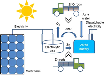
Figure 1. A proposed Zn↔ZnO loop for long-term storage and global trade of solar electricity. 1,4,7 Zn rods are produced from ZnO by solar electrolysis. They are shipped and inserted into Zn/air batteries to generate electricity on demand. The spent Zn anodes are collected for regeneration of Zn.
Download figure:
Standard image High-resolution imageThe proposed Zn↔ZnO loop relies on the same principle as in an electrically-recharged zinc/air battery. When the battery is charged, the ZnO in the anode is reduced to zinc. When it is discharged, the anode zinc is oxidized into ZnO. By dividing the two functions of a storage battery (i.e., storage and generation) into two separate devices (an electrolyzer for storage and a mechanically-recharged zinc/air battery for generation), the proposed Zn↔ZnO loop offers several advantages over hydrogen storage. The first and foremost is that zinc rods are much easier and safer to store and transport than hydrogen. Zinc rods can be stacked up and stored in any warehouse, and their storage does not require energy or specialized containers. They can be packed in crates or cardboards for shipping. They can be handled with bare hands as they are non-hazardous to humans or the environment. Compared to an electrically-recharged zinc/air battery, the charge cycle is significantly improved as the physical and/or chemical changes in the anode due to repeated charge/discharge cycles are eliminated. The shelf life is also significantly increased as the zinc rods can be stored almost indefinitely at little cost and with no energy loss. There is also the possibility of integrating the zinc/air battery with a photovoltaic system and the electric grid at user sites to smoothen out the intermittent solar electricity from the photovoltaic system, 7 thus minimizing the negative impact of solar electricity on the grid.
Between hydrogen and zinc as the storage medium, it takes 50–55 kWh of electricity to produce 1 kg of hydrogen from water, 6 but it is 2.5–2.7 kWh to produce 1 kg of zinc from ZnO. 8 On the other hand, the Gibbs free energy is –237.2 kJ mol−1 for water and –320.5 kJ mol−1 for ZnO, 9 which represent the maximum possible amount of energy which can be release when hydrogen or zinc is oxidized into water or ZnO. Therefore, 1 kWh of solar electricity can provide up to 2,353 kJ of energy through hydrogen but 1,961 kJ through zinc. They are listed in Table I under energy capacity. The more significant disadvantage of zinc is that the spent anode must be collected and shipped back for regeneration of zinc, while nature cycles back the product of hydrogen usage, water. Another difference between hydrogen and zinc is that as a gas, hydrogen can be transported through pipelines. Therefore, hydrogen is better suited for regional trade of solar electricity, for example from Arizona to Chicago through a pipeline, while zinc rods are better for global trade of solar electricity. In terms of duration, hydrogen is better for short to medium-term storage from weekly to maybe monthly and zinc is better for long-term storage from seasonal to multiyear. Table I summarizes the comparison.
Table I. Comparison of hydrogen and zinc as storage media.
| Medium | Duration | Energy Capacity | Specialized containers | Energy for storage | Pipeline transport | Return required |
|---|---|---|---|---|---|---|
| H2 | Weekly/Monthly | 2,353 kJ kWh−1 | Yes | Yes | Yes | No |
| Zn | Seasonal/Multiyear | 1,961 kJ kWh−1 | No | No | No | Yes |
There are more than a dozen metals which could be used in a metal↔metal oxide loop for long-term storage and global trade of solar electricity, but the Zn↔ZnO loop is the best overall pick based on four factors: material abundance, theoretical performance, process practicality, and technical readiness.
Scalability of the Zn↔ZnO loop
We can estimate the amount of zinc required for long-term storage of solar electricity. In another paper in this Focus Issue, 10 we argue that by 2050, the scale of installed solar panels must reach about 100 TWp in order to reduce our carbon emission by about 25% from the 2020 level. With a 100 TWp solar electricity capacity by 2050, a significant portion would require storage. Let us assume that 90% of the 100 TWp capacity would be consumed in real time or stored for short to medium terms. That is, only 10% of the 100 TWp capacity requires long-term storage, which is 10 TWp. Due to the intermittency of solar energy and the power losses in photovoltaic systems, the time-averaged output of a solar panel is about 15% of its peak wattage. Therefore, the amount of solar electricity for long-term storage on a daily basis is 100 TWp × 10% × 24 h/d × 15% = 3.6 × 10¹⁰ kWh d−1.
The Gibbs free energy of ZnO is –320.5 kJ mol−1 or –0.089 kWh mol−1 at 25 °C. 9 To store 3.6 × 10¹⁰ kWh of solar electricity on a daily basis, we need at least 3.6 × 10¹⁰ ÷ 0.089 = 4.0 × 10¹¹ moles of zinc a day or about 26 million tons (Mt) of zinc a day. If the turn-around time between shipping zinc rods to users and getting spent anodes back for regeneration is 180 days, the total amount of zinc required is 180 days × 26 Mt/d = 4.8 billion tons (Bt). The known reserve of zinc on our planet is 1.9 Bt, 11 may or may not enough for the proposed storage loop. This highlights the importance of Earth-abundant materials as the media for solar electricity storage.
The estimation above is rough and many of the numbers used are arguable. The point of the estimation is that whatever storage medium we choose, the amount of the material required is likely in the range of billion tons.
Theoretical performance
There are about a dozen metals which have a reserve of at least 1 Bt according to Ref. 11. Most of them are listed in Table II. The storage medium should come from this table, and the question now is which metal should be our choice?
Table II. Figure of merit for Earth-abundant metal↔metal oxide loops and their standard reduction potentials. 1,7
|
We can estimate the theoretical performance of different metal↔metal oxide loops for storage of solar electricity. A figure of merit (FoM) is defined as the ratio between the maximum possible amount of energy to be released when a metal oxidizes and the minimum amount of charge needed to reduce its oxide to metal:

The unit for figure of merit is joule/coulomb (J/C). The minimum amount of charge to reduce 1 mole of a metal oxide is calculated from the valence of the metal in the oxide assuming a 100% coulombic efficiency.
Table II lists the figures of merit for a dozen Earth-abundant metals. They are listed in the order of decreasing figure of merit, except for water and carbon dioxide (CO2). Burning fossil fuels takes the C↔CO2 loop. The H2↔H2O loop has been proposed for storage of solar electricity. They are not as good as the Zn↔ZnO loop in terms of theoretical performance. This contradicts Table I in which hydrogen is slighter better than zinc in terms of energy capacity per kilowatthour of solar electricity. The discrepancy is attributed to the different energy efficiencies of the two electroreduction processes due to factors like over-potential. 6 A high over-potential increases the throughput but reduces the energy efficiency.
Process practicality
There are eight metals which have better figures of merit than Zn↔ZnO in Table II, but they are excluded due to process practicality or technical readiness.
Electroreduction of a metal oxide to metal is performed either in an aqueous solution or molten salt. A major difference between the two electrolytic processes is the temperature. Aqueous electrolysis is carried out at or near room temperature, but molten-salt electrolysis requires a high temperature around 1000 °C. The difficulty comes when we try to drive molten salt electrolysis by solar energy. That is, how do we keep the salt at 1000 °C for more than 15 h a day from late afternoon to early morning? We could use fossil fuels or grid electricity to maintain the temperature, but they undo the purpose of solar electricity storage. Even during daytime, concentrated solar power is needed to heat the salt to 1000 °C. Therefore, solar-powered molten-salt electrolysis requires a far more complicated setup than solar-powered aqueous electrolysis. In addition, concentrated solar power curtails the geographic applicability of molten-salt electrolysis as it requires direct-beam sunlight.
The last column in Table II lists the standard reduction potentials of Earth-abundant metal redox pairs. 9 The standard reduction potential of water is –0.8277 V vs the standard hydrogen electrode. Oxides of calcium, magnesium, aluminum, barium, and titanium (CaO, MgO, Al2O3, BaO, and Ti3O5) all have more negative reduction potentials than water, so they require molten-salt electroreduction which is unsuitable for solar electricity storage. If one tries electroreduction of these oxides in an aqueous solution, the product is not the metal but hydrogen.
Technical readiness
The two key technologies needed to practice the proposed metal↔metal oxide loop are:
- An electroreduction process of a metal oxide in an aqueous solution, and
- A mechanically-recharged metal/air battery for the metal.
In Table II, there is no established electroreduction process for oxides of silicon and boron (SiO2 and B2O3). For chromium oxide (Cr2O3), we have not found any report on a chromium/air battery.
Now we are down to Zn↔ZnO in Table II. Zinc is Earth abundant. The figure of merit for Zn↔ZnO is 1.66 J C−1, better than H2↔H2O. Commercially zinc is produced electrolytically from zinc sulfate (ZnSO4) by dissolving ZnO in sulfuric acid (H2SO4). 12 Solar electroreduction of zinc oxide uses the same commercial process. Zinc/air batteries for solar electricity storage are being commercialized as they have a lower cost than other battery technologies for storage, 4,13 although the research focus has been on electrically-recharged batteries instead of mechanically-recharged ones. 13 Therefore, the two technologies required to practice the Zn↔ZnO loop are commercially either available or almost ready.
The annual global production of zinc is about 13 Mt today, 11 but the Zn↔ZnO loop requires 26 Mt of zinc a day. Even with an Earth-abundant metal, the challenges for long-term storage of solar electricity are still significant as the zinc production needs to be scaled up by about 740 times. The technologies yet to be developed for the Zn↔ZnO loop include:
- A low-cost high-efficiency system for solar electrolysis, and
- An optimized zinc/air battery specifically for mechanical recharging.
Electrorefining for Solar-Grade Silicon
The silicon used in solar panels has a very high purity of at least 6 N's (>99.9999%). Figure 2 shows the current industrial process to produce solar-grade silicon. 1,14,15 Metallurgical-grade silicon first reacts with hydrogen chloride (HCl). The resultant trichlorosilane (SiHCl3) is purified by fractional distillation. The purified SiHCl3 is then reduced to solar-grade silicon in a cold-wall chemical vapor deposition reactor. This is the well-known Siemens process.
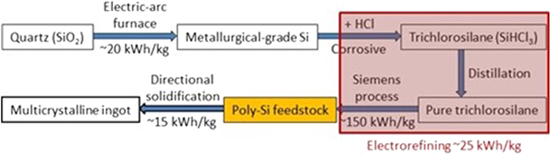
Figure 2. The current industrial process to produce solar-grade Si and the proposed electrorefining route for solar-grade Si. 1,14,15
Download figure:
Standard image High-resolution imageThe Siemens process is notoriously nasty and energy intensive. The chlorides involved (HCl, SiHCl3, SiH2Cl2, SiCl4, etc.) corrode and require periodic replacement of the stainless-steel distillation system. The energy intensity of the Siemens process is extremely high at about 200 kWh kg−1 of solar-grade silicon produced, 15,16 making solar-grade silicon one of the most energy-intensive products we produce. It is estimated that the electricity intensity to produce 1 Wp of silicon solar panel is about 3 kWh, 1 resulting in an energy payback time of about 2 years for panels installed in Arizona.
Electrorefining promises a much more energy efficient and cleaner route to solar-grade silicon from metallurgical-grade silicon. 17 As shown in Fig. 2, the objective is an electrorefining process to replace the Siemens process for purification of silicon. It eliminates all the chloride gases while promising an 85%–90% energy saving over the Siemens process. A Stanford group estimated the electricity intensity at 16 kWh kg−1 for electrorefined silicon. 18 A more recent paper reported 9.3 kWh kg−1 of silicon in molten calcium chloride at about 900 °C. 19 As discussed later in this paper, we are using a two-step electrorefining process to achieve solar-grade silicon and our estimation is about 25 kWh kg−1 of solar-grade silicon by electrorefining.
Molten-salt electrorefining for ultrapure solar-grade silicon was first explored by a French group in 1964. 17 Since then a dozen or so groups worldwide have attempted silicon electrorefining, but ultrapure solar-grade silicon by electrorefining remains elusive. Reference 20 provides a review of silicon electrorefining efforts up to about 2010. Since then the most notable result is probably the recent work at the University of Texas at Austin where 5 N silicon (99.999%) by molten-salt electrolysis is demonstrated. 21 The photocurrent of their electrodeposited silicon films reached about 45% of an n-type Czochralski silicon wafer. While the results are impressive, the purity of the silicon is insufficient for a high-efficiency cell. Ultrapure materials by electrorefining remains an unanswered challenge in electrochemistry.
Our approach for ultrapure silicon
It is noticed that almost all the prior efforts on silicon electrorefining utilized the two-electrode electrolyzer as shown in Fig. 3, with an anode and a cathode. This two-electrode configuration is widely employed in the chemical and mining industries to electrolytically produce various raw materials, although the specifics for the electrolyzer are different depending on the material produced. The highest purity it has achieved is about 3 N's, but those electrolytically-produced materials do not require an ultrahigh purity. Electrorefining relies on the different redox potentials of various impurities from silicon. Therefore, controlling the potential applied for oxidation or reduction is critical to achieve an ultrahigh purity. In the two-electrode electrolyzer, the potential difference between the anode and cathode is controlled, but there is no way to independently control the oxidation potential on the anode or the reduction potential on the cathode. This is why ultrapure materials are difficult in the two-electrode electrolyzer. 22 The only paper we have found on three-electrode silicon electrorefining did not investigate the effect of anode or cathode potential on the purity of the produced silicon. 23

Figure 3. The two-electrode electrolyzer to purify Si.
Download figure:
Standard image High-resolution imageWe are taking a new approach to silicon electrorefining in an attempt to achieve ultrapure silicon of 6 N's–9 N's. 22 It involves three-electrode electrolysis in two steps in a molten salt (Fig. 4). In the first step, metallurgical-grade silicon is the anode and the anode potential is controlled vs a reference electrode to keep all the more noble impurities than silicon in the anode (e.g., boron, phosphorous, iron, and copper). In the second step, the cathode from the first step is used as the anode, and the potential on the new cathode is controlled to keep the less noble impurities than silicon in the salt (e.g., aluminum and calcium). The cathode from the second step is expected to be solar-grade silicon with at least a 6 N purity.
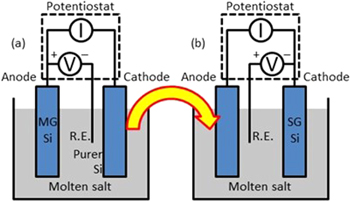
Figure 4. Our proposed three-electrode two-step electrolysis to purify Si. 22
Download figure:
Standard image High-resolution imageOur approach is analogous to the fractional distillation process for SiHCl3. There are two steps in fractional distillation. In the first step, the vaporization temperature is controlled vs a reference temperature (e.g., the freezing point of water, 0 °C) to keep all the chlorides with boiling points higher than SiHCl3 in the liquid phase. In the second step, the vapor from the first step is condensed and the condensation temperature is controlled to keep all the chlorides with boiling points lower than SiHCl3 in the gas phase. That is, each step can remove only one type of impurities with a common characteristic.
Impurity segregation in electrolysis
We have extended the Nernst equation for impurity segregation in electrolysis.
22
The segregation coefficient,  is defined as the concentration ratio of an impurity in an electrode (either anode or cathode) and in the molten salt:

The applied reduction potential  and the segregation coefficient follow the revised Nernst equation
22
:
and the segregation coefficient follow the revised Nernst equation
22
:

where  is the standard reduction potential,
  the gas constant,
  the absolute temperature,
  the Faraday constant, and
  the number of electrons transferred in the redox reaction. The purpose of electrorefining is to maximize the segregation coefficient for the anode,
  in the first step of Fig. 4 so impurities stay in the anode and minimize it for the cathode,
  in the second step so impurities remain in the salt.
Figure 5 plots Eq. 3, i.e., segregation coefficient vs under-potential  at 850 °C for different
  values. Obviously the segregation coefficient in electrolysis is controlled by the applied potential. By switching from an under-potential to an over-potential, the segregation coefficient changes from smaller than unity to larger than unity. That is, we can keep an impurity either in the salt (by an under-potential) or in the anode (by an over-potential). By increasing the applied potential, we can also push the segregation coefficient far away from unity. Therefore, electrorefining is more versatile and effective than purification methods based on impurity segregation between two phases (e.g., between silicon melt and silicon solid in float-zone growth), for which the segregation coefficient of an impurity has a fixed value at the melting point of silicon.
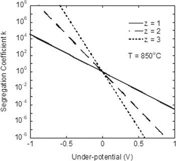
Figure 5. Segregation coefficient vs under potential at 850 °C. 22
Download figure:
Standard image High-resolution imageEquation 3 also provides the required potentials to achieve solar-grade silicon if the electrorefining process is run under equilibrium. 22 Table III shows the impurity concentrations in the salt at 850 °C when 2.064 V vs the O2/2O2– reference electrode is applied to the working electrode serving as the anode. All the standard reduction potentials at 850 °C in a molten salt are from Ref. 24. For silicon, it is –1.99 V vs O2/2O2–. With the typical impurity concentrations in metallurgical-grade silicon 25 (column 2 in Table III), the concentrations of all the impurities in the salt (last column) are below the targets for solar-grade silicon (column 3).
Table III. Impurity segregation between anode and salt at 2.064 V vs O2/2O2– and 850 °C. 22
| Impurity | MG-Si (ppm) | SG-Si (ppm) | Redox pair |

|

|
 achieved achieved |
 (ppm) (ppm) |
|---|---|---|---|---|---|---|---|
| B | 40 | <1 | B3+/B | –1.63 V | –0.434 V | 8.00 × 10⁵ | 5.00 × 10⁻⁵ |
| P | 20 | <5 | P2+/P | –1.27 V | –0.794 V | 1.59 × 10⁷ | 1.26 × 10⁻⁶ |
| O | 3000 | <10 | O2/2O2– | 0.00 V | –2.064 V | 1.23 × 1036 | ∼0 |
| C | 600 | <10 | C4+/C | –1.07 V | –0.994 V | 4.84 × 10¹⁶ | ∼0 |
| Fe | 2000 | <10 | Fe3+/Fe | –0.81 V | –1.254 V | 1.12 × 10¹⁶ | ∼0 |
| Ti | 200 | <1 | Ti2+/Ti | –1.81 V | –0.254 V | 201 | 0.995 |
| Cu | ? | ? | Cu2+/Cu | –0.22 V | –1.844 V | 1.12 × 10¹⁶ | ~0 |
Controlling the anode potential removes only those more noble impurities than silicon. A second electrorefining step removes those less noble impurities than silicon. Table IV lists the impurity concentrations in the cathode at 850 °C when –2.083 V vs O2/2O2– is applied to the working electrode as the cathode. All the impurity concentrations in the cathode are within the targets for solar-grade silicon. That is, a two-step three-electrode process has the potential to achieve solar-grade silicon from metallurgical-grade silicon.
Table IV. Impurity segregation between salt and cathode at –2.083 V vs O2/2O2– and 850°C. 22
| Impurity | MG-Si (ppm) | SG-Si (ppm) | Redox pair |

|

| k achieved | Ccathode (ppm) |
|---|---|---|---|---|---|---|---|
| Al | 200 | <2 | Al3+/Al | –2.23 V | 0.24 V | 1.00 × 10⁻² | 2.00 |
| Ca | 600 | <2 | Ca2+/Ca | –2.56 V | 0.57 V | 4.73 × 10⁻⁵ | 2.84 × 10⁻² |
Practical challenges
The section above describes idealistic, simplistic, and equilibrium electrorefining, but the actual molten-salt silicon electrorefining process can be much more complicated. Kinetics will no doubt play a significant role. It is also possible that the system involves irreversible reactions and/or formation of complexes, which may prevent effective electrorefining.
There are more practical challenges. Molten-salt electrolysis requires about 1000 °C. At this temperature, silicon is oxidized in air and the electrically-insulating SiO2 formed on the surface of silicon electrodes prevents further electrorefining. 24 Therefore, silicon electrorefining must be carried out in high vacuum of about 10–6 Torr. On the other hand, the salts used for silicon electrorefining are usually chlorides and fluorides. They have vapor pressures in the millitorr range at 1000 °C. Performing a high-temperature process in high vacuum with a highly corrosive vapor is by no means an easy task. Some of the difficulties include:
- Metallic contamination: Vacuum chambers are typically made of stainless steel which contains iron. Electrical wires are typically made of copper. Both are detrimental to solar-grade silicon even in the smallest amount. The apparatus can be designed in such a way that the iron or copper-containing components are not in direct contact with silicon, but the presence of fluorine and chlorine at high temperatures could carry iron and copper around through the gas phase causing contamination.
- Corrosion of apparatus: Not many materials can withstand fluorine and chlorine at high temperatures. For example, we have noticed that a molybdenum component rusted like a piece of iron in seawater after several months in the apparatus. We have so far identified several materials which are stable under these conditions including graphite, glassy carbon, alumina (Al2O3), and aluminum. There are also design tricks to minimize the detrimental impact of fluorine and chlorine. All these challenges must be overcome before electrorefined solar-grade silicon becomes a reality.
Metal Recovery From Waste Panels
Another roadblock to sustainable deployment of solar panels is the waste panels. According to the International Renewable Energy Agency, there would be 78 Mt (million tons) of waste panels cumulative by 2050 or 6 Mt/year in 2050. 26 This is likely an underestimate as the 2019 panel production was about 130 GWp 27 or about 8 Mt. With a typical panel lifetime of 25 years, these 2019 panels would become waste in 2044. By 2050, waste panels are likely to exceed 10 Mt/year.
While more and more attention is drawn to this emerging roadblock, solar panel recycling is seldom done due to the high cost. 28 With today's technology, each 60-cell silicon panel can generate about $3 from the recovered materials: aluminum frame, copper wiring, and glass cullet. However, the cost to recycle a silicon panel in the US currently exceeds $30 including the costs to decommission, package, ship, and process the panel. Technologies are needed to increase the revenue from and reduce the cost for panel recycling.
Recycling scenarios
There are three scenarios for decommissioned solar panels: panel reuse, component reuse, or material reuse. 28 If a decommissioned panel is still functional, it could be reused as a lower-quality product. If the panel is not reusable due to damage or low efficiency, the components in the panel could be recovered for reuse including the silicon cells and the glass pane. If the components are not reusable, the materials in the components could be extracted for reuse including silver, lead, tin, copper, and silicon. Table V provides the metallic contents of a typical silicon panel. 29
Table V. Metallic contents of silicon panels by weight percent. 29
| Material | Weight% |
|---|---|
| Al | 10 |
| Si | ∼3% |
| Sn | 0.12 |
| Pb | <0.1 |
| Cu | 0.6 |
| Ag | <0.006 |
Component reuse is unlikely to be practiced in the near future. This is because of the many different types of silicon cells in commercial panels today. 28 Different cell structures produce different powers and efficiencies. Even for cells of the same structure, there are efficiency variations of about 2% absolute. For example, the efficiency of commercial aluminum back-surface field cells varies between 17% and 19%. Cells of different power, efficiency, voltage, or current can not be packaged into the same panel due to mismatch losses. With the dozen or so different cell structures and efficiency variations for the same cell structure, collecting cells of the same structure and matched efficiency is a significant challenge for the recyclers. They would have to have hundreds of bins, each for a particular cell structure with a particular efficiency. They would have to process a large number of waste panels before enough cells of the same structure and same efficiency could be accumulated for a new panel. This would significantly increase the cost of reused components.
Several companies are in the panel reuse business today. It generates a relatively-high revenue, about $20/panel, with few processing steps. The uncertainty for panel reuse is whether there will be a large and sustained market on the order of several hundreds of gigawatts peak a year for reused panels? 28 Material reuse generates a lower revenue. Table VI shows the potential revenue if all the materials were extracted in their pure, high-value forms from silicon panels, $8.45/panel. 28 The valuable materials include silver, aluminum, glass, silicon, and copper. Aluminum and glass come from the panel, and Fig. 6 shows the structure of the most-common commercial silicon panels without the junction box. Silver and silicon come from the cells (Fig. 7). Lead comes from the solder in the cells, which must be removed from the recycling sludge as it is toxic. Although material reuse generates a lower revenue, it is the ultimate solution as reused panels will eventually fail and require material extraction.
Table VI. Potential revenue from a 60-cell Si back-surface field panel as of 10/30/2019, $8.45/panel. 28
| Material | Recovery % | Value | % Total |
|---|---|---|---|
| Glass | 100% | $1.35 | 16.0 |
| Al | 100% | $1.74 | 20.6 |
| Polymers | 67% | n/a | 0 |
| Si | 100% | $0.93 | 11.0 |
| Pb | 100% | $.02 | 0.2 |
| Cu | 100% | $0.55 | 6.5 |
| Ag | 100% | $3.73 | 44.1 |
| Sn | 100% | $0.13 | 1.5 |

Figure 6. Structure of the most-common Si panels without the junction box.
Download figure:
Standard image High-resolution image
Figure 7. Structure of the Al back-surface field cell.
Download figure:
Standard image High-resolution imageRecycling processes and technologies
Figure 8 compares the current recycling process with the two processes we propose, one for panel reuse and one for material reuse. 28 The current process recovers only aluminum, glass, and copper for about $3/panel. Panel reuse generates the highest revenue ($20/panel) with the fewest processing steps, while material reuse produces a reasonable revenue ($8/panel) with the most processing steps. For this reason, all the decommissioned panels should begin with the same processing steps to check their reusability. If panel reuse is not possible, more processing steps are added for material extraction. Therefore, the first two steps are identical for the proposed processes in Fig. 8.
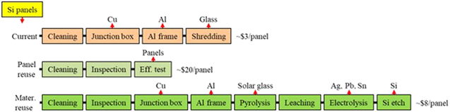
Figure 8. Comparison of the current recycling process with proposed recycling processes for Si panels. 28
Download figure:
Standard image High-resolution imagePanel reuse is being practiced today. For material extraction, there are commercial tools to strip the junction box off for copper and then strip the aluminum frame off. After removal of junction box and aluminum frame, most recyclers today shred the remaining panels for glass, so the silicon cells with silver and lead are shredded with the glass. Our proposed process for material reuse requires a technology to cleanly separate the cells from the glass so the materials in the cells can be extracted. A Japanese company, NPC Incorporated, developed a hot-knife method in which a steel blade heated to about 300 °C slices through the ethylene vinyl acetate (EVA) layer to separate the cells from the glass. 30 After hot knife, the polymers including the ethylene vinyl acetate encapsulant and the fluoropolymer backsheet must be removed from the glass and the cells by pyrolysis. 28 The glass cullet after pyrolysis becomes high-transparency solar glass cullet and the cells without polymers enable material extraction.
Metal recovery by sequential electrowinning
The metals worth recovery from silicon cells include silver from the electrodes, lead and tin from the solder, copper from the interconnection, and silicon (Fig. 7). The silicon nitride (SiNx) antireflection layer and the aluminum back electrode are difficult to recover and they have little value. 28
The approaches in the literature for metal extraction from silicon cells all involve chemicals. 28,31 The most common chemical to leach metals out of silicon cells is nitric acid (HNO3). 32 Silver, lead, and copper dissolve in it. Tin precipitates out as white powder of tin oxide (SnO2) in HNO3, which requires filtration or sedimentation to recover. Although the metallic contents in silicon panels are low (Table V), the nitric leachate can process many batches of silicon cells so it contains high concentrations of the metals. Now the task is to extract the multiple metals from the leachate one by one in their pure forms. There are two methods in the literature which deal with multiple metal recovery from the leachate. Jung et al. 33 used more than half a dozen different chemicals in combination with chemical extraction, electrowinning, and filtration to recover the three metals.
A simpler method for multiple metal recovery from the leachate is sequential electrowinning. 32 The nitric leachate contains three metals: silver, lead, and copper. As shown in Table VII, they have different reduction potentials vs the standard hydrogen electrode. We can apply an appropriate reduction potential on the cathode to extract silver first. Once silver is gone, a more negative potential is applied to recover copper. Finally an even more negative potential would recover lead.
Table VII. Standard reduction potentials for Ag, Cu, and Pb.
| Redox Pair |
 (V) (V) |
|---|---|
| Ag+/Ag | 0.7996 |
| Cu2+/Cu | 0.3419 |
| Pb2+/Pb | –0.1262 |
The method has been demonstrated and reported in Ref. 32. A three-electrode electrolyzer was used for the experiment, with a titanium working electrode as the cathode, a platinum counter electrode as the anode, and a silver/silver chloride (Ag/AgCl) reference electrode. Figure 9 is the schematic of the electrolyzer. Figure 10 shows the voltammetric scans of the leachate before and after silver recovery. Before silver recovery, the silver reduction peak occurs around 0.35 V vs the Ag/AgCl reference electrode and copper reduction around 0.1 V. The lead reduction peak is overshadowed by the copper peak as the concentration of copper is about 10 times higher than that of lead in the leachate. For silver recovery, a potential of 0.3 V vs Ag/AgCl was applied for 5.5 h. After the silver was extracted, the silver peak disappeared in the voltammetric scan (Fig. 10). A potential of 0.1 V vs Ag/AgCl was then applied for 24 h causing copper to deposit on the cathode. It was also noticed that when copper was depositing on the cathode, the lead in the leachate was further oxidized and deposited on the anode. That is, instead of a three-step electrowinning process, the three metals in the nitric leachate can be recovered in their pure forms by two-step sequential electrowinning.
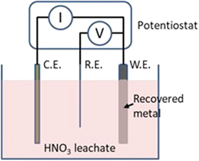
Figure 9. A three-electrode electrolyzer for sequential electrowining of metals.
Download figure:
Standard image High-resolution image
Figure 10. Voltammetric scans of the nitric leachate before and after Ag recovery. 32
Download figure:
Standard image High-resolution imageFigure 11 shows an energy-dispersive X-ray analysis of the electrowon silver. Only two elements are observed: silver and titanium from the cathode. With a detection limit better than 1%, the electrowon silver is at least 99% pure. Figure 12 shows the energy-dispersive X-ray analyses of the deposits on the cathode and the anode during copper recovery. Since there is more copper than silver in the leachate, the thick copper deposit covers the titanium cathode and prevents it from being detected. On the anode, both the platinum anode and lead are detected.
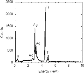
Figure 11. Energy-dispersive X-ray analysis of electrowon Ag. 32
Download figure:
Standard image High-resolution image
Figure 12. Energy-dispersive X-ray analyses of (a) electrowon Cu and (b) Pb deposited on the Pt anode. 32
Download figure:
Standard image High-resolution image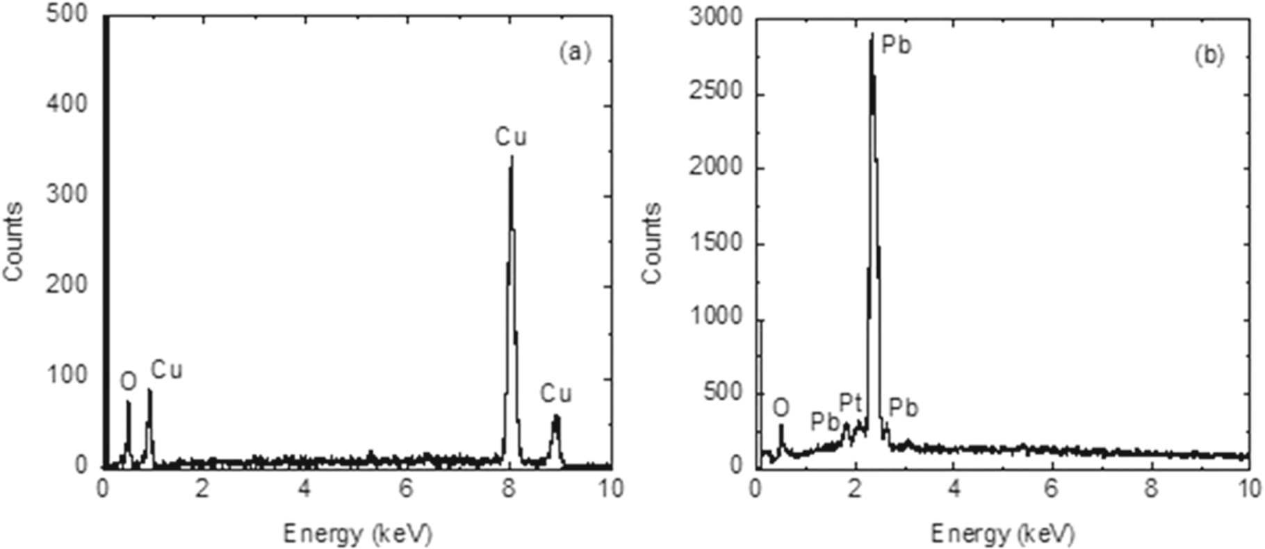
One of the major issues with sequential electrowinning is the costly platinum anode, which must be replaced with a low-cost anode. Another significant issue is the low silver recovery rate. With a nitric leachate, the silver recovery rate is only about 70%, copper 80%, but lead has a good recovery rate of 99%. 32 As shown in Table VI, silver is the most valuable material from silicon panels. Recovering only 70% of the silver means we would lose about $1.10/panel in potential revenue. The reason for the low silver and copper recovery rates is the thin, dendritic silver and copper deposits on the cathode. They often detach from the cathode and then redissolve in the nitric leachate. Innovations in leaching chemistry and/or electrowining method are needed to improve the silver and copper recovery rates to 100%.
Conclusions
Electrochemistry will play an indispensable role in removing several roadblocks to sustainable solar photovoltaics. This paper presents three examples. The first example is storage of intermittent solar electricity through a Zn↔ZnO loop which requires two technologies: (1) solar electroreduction of ZnO and (2) a mechanically-recharged zinc/air battery. Compared to the H2↔H2O loop, the Zn↔ZnO loop is advantageous for long-term (seasonal to multiyear) storage and global trade of solar electricity. The second example is electrorefining to produce solar-grade silicon from metallurgical-grade silicon. Ultrapure materials by electrolysis is an unanswered challenge in electrochemistry. A two-step three-electrode electrorefining process is proposed. Practical challenges in achieving ultrapure silicon by molten-salt electrorefining are outlined. The third example is metal recovery from waste solar panels. Four metals in silicon panels are worth recovery: silver, lead, tin, and copper. They can be leached out in HNO3 and the leachate contains multiple metals. Sequential electroinning can recover the metals one by one based on their different reduction potentials. The remaining issues in this process are discussed.
Acknowledgments
The author is grateful to several colleagues who have contributed to various projects reported in this paper, Drs. X. Han, W.-H. Huang, M.-F. Tseng, Profs. D. H. Wang and K. Rajeshwar. Financial support for the various projects was provided by multiple grants from the National Science Foundation and the Department of Energy Solar Energy Technologies Office.