

Abstract
This work demonstrates how the interaction between particle image velocimetry (PIV) and robotics can massively increase measurement efficiency. The interdisciplinary approach is shown using the complex example of an automated, large scale, industrial environment: a typical automotive wind tunnel application. Both the high degree of flexibility in choosing the measurement region and the complete automation of stereo PIV measurements are presented. The setup consists of a combination of three robots, individually used as a 6D traversing unit for the laser illumination system as well as for each of the two cameras. Synchronised movements in the same reference frame are realised through a master-slave setup with a single interface to the user. By integrating the interface into the standard wind tunnel management system, a single measurement plane or a predefined sequence of several planes can be requested through a single trigger event, providing the resulting vector fields within minutes.
In this paper, a brief overview on the demands of large scale industrial PIV and the existing solutions is given. Afterwards, the concept of RoboPIV is introduced as a new approach. In a first step, the usability of a selection of commercially available robot arms is analysed. The challenges of pose uncertainty and importance of absolute accuracy are demonstrated through comparative measurements, explaining the individual pros and cons of the analysed systems. Subsequently, the advantage of integrating RoboPIV directly into the existing wind tunnel management system is shown on basis of a typical measurement sequence. In a final step, a practical measurement procedure, including post-processing, is given by using real data and results. Ultimately, the benefits of high automation are demonstrated, leading to a drastic reduction in necessary measurement time compared to non-automated systems, thus massively increasing the efficiency of PIV measurements.
Export citation and abstract BibTeX RIS

Original content from this work may be used under the terms of the Creative Commons Attribution 3.0 licence. Any further distribution of this work must maintain attribution to the author(s) and the title of the work, journal citation and DOI.
1. Introduction
Using PIV in a large scale industrial environment is not a new challenge. Industry is always looking for faster design cycles and shorter time to market their products. This also applies for PIV measurements used in the development phase, as already mentioned in 2000 by Stanislas et al [1]. Cardano et al [2] emphasised the importance of fast PIV measurements and postprocessing techniques due to the high operational costs of large scale wind tunnels. Recent developments in volumetric PIV or 3D PTV approaches have improved the attractiveness of these techniques for industry. The work of Scarano et al [3] on the use of helium-filled soap bubbles largely increases the size of the measurement volumes. In parallel, the advancements in postprocessing provide a higher accuracy and spatial resolution; see Schanz et al [4].
1.1. Challenges of large scale industrial PIV
There are still some factors causing problems for large format industrial measurements:
- Most of the time, the optical access is limited. This restricts the available measurement regions, especially for multi-camera set-ups.
- There are not many examples known in which large particles, such as helium-filled soap bubbles, are used at velocities higher than 30 m s−1.
- The spatial resolution for larger volumes is limited.
- Due to the time required for postprocessing, the resulting vector field is not readily available after the measurement.
Plenoptic cameras provide an alternative for the multi-camera approach, but introduce other problems related to the resolution along the optical access; see Deem et al [5].
At the moment, PIV only plays a minor role in the world of large-scale industrial flow field analyses. The most typical task nowadays can be described as 'service measurements', where a PIV system is temporarily installed in an industrial wind tunnel and run by specially trained personnel. Most of the time these measurements only serve as validation data for CFD results. The unpopularity of PIV for industrial development processes can be directly linked to its poor cost-benefit ratio. Besides the initial costs and the technical restrictions mentioned above, large limiting factors can be identified as facility downtime, human interaction during execution of the experiment and the necessary on-site know-how. Although automation was partly possible, the strict sequence of calibration, measurement and post processing was always interrupted by mandatory manual interventions. These bear the risk of introducing inaccuracies or, in the worst case, even failure of experiment. On top of that, the results are not available shortly after the experiment. Depending on the region on which the development is focused, it is not sufficient to acquire only a certain number of predefined measurement planes. The output of a few static, predefined planes does not justify the combined cost of hardware and its operation, including personnel costs. Due to the aforementioned challenges, only a few examples of large-format industrial PIV are known [6].
1.2. PIV in formula 1 and other industrial applications
The formula 1 world is known for its advanced technology and quick development pace, for which large amounts of money are being spent. In an attempt to equalise the field and reduce the yearly budgets, the governing body of Formula 1 introduced several limitations for the development process [7]. For the aerodynamicists this means a limitation of available wind tunnel hours and the number of floating point operations per second, expressed in TeraFLOPS, for CFD simulations. In practice, a compromise between the number of experiments and simulations needs to be found; see figure 1.

Figure 1. Trade-off between wind tunnel hours and CFD TeraFLOPS, according to [8].
Download figure:
Standard image High-resolution imageSince the available time in the wind tunnel is now limited, doing PIV measurements becomes much more difficult. The typical process of setting up the equipment, calibrating, measurement, re-positioning the equipment, re-calibrating and so on, takes up too much time from the available budget. The use of linear traverses, as presented by Nakagawa [6], makes the complete process a bit more efficient but the system is not fast and flexible enough to become a part of the standard development process. When the model of the car is rotated to measure cross-wind conditions for example, the measurement plane ideally follows the motion of the car. With linear traverses and rotational stages, this becomes a very difficult job.
These type of requirements for the flow measurement system are not just dedicated to formula 1. Wind tunnels for automotive development and also other industries are expensive to run and the available time for the experiment is limited. In addition the available personnel is not necessarily familiar enough with PIV to do the set-up. Therefore, the PIV system should be able to run automatically without human interaction and be flexible enough to measure around the complete model, e.g. car, plane, boat etc, without the need for a new calibration process.
2. Introduction of robotics to PIV
With the recent advancements in the field of automation and industrial robotics, a higher benefit can be gained from a PIV set-up. Industrial robots (IR) can operate with high repeatability while moving at high speeds. They are designed for 24/7 use and are established as very reliable machines in the field of automated production lines. In the recent years, advanced control hardware and software is used for cooperative robotics, e.g. industrial robots need to perform handling procedures which are synchronised with assembling operations of additional industrial robots in a cooperative way. Fast bus-specific, real-time communication protocols like e.g. Sercos, Ethercat enable the IR controllers to synchronise the movements of the robots in a master-slave setup, so the movement of the slave is determined by the master. Using several industrial robots, the perfect base for positioning both laser and cameras of a PIV set-up is found. A fully functional RoboPIV System allows sequential measurements at a multitude of positions, making use of all six degrees of freedom (6 DoF) of the used robots. Once calibrated, the relative position of laser and cameras remains the same due to the master-slave setup. This allows measurements at any arbitrary position around the object of interest and within the working range of the IR. To increase the operating range of the system, each IR can be mounted on additional external axes, shown in figure 2. This example shows an 'inverted' set-up, in which the robots are fixed upside down to the linear traversing system. This keeps to area below the robots free and allows for both laser and cameras to measure close to the ground without any interference.

Figure 2. Stereo RoboPIV for automotive industry.
Download figure:
Standard image High-resolution image2.1. Pose uncertainty of industrial robots
The pose of a 6 DoF robot is a combination of the 3D position  of its tool centre point (TCP) and its orientation angles (roll, pitch, yaw). The pose accuracy and pose repeatability are part of the performance characteristics of manipulating industrial robots, described in DIN EN ISO 9283 [9]. This standard defines the methods to be applied in order to quantify the uncertainties in both pose accuracy and repeatability of an industrial robot. The correct choice of the measurement equipment is not specified and left to the user. Following this standard, most of the manufacturers characterise their robot arms in the data sheet by using the repeatability of pose. For e.g. pick and place procedures where mostly saved poses are used, this is sufficient to characterise the possibility of the procedure. Most of the arms achieve a quite low uncertainty for the repeatability. The absolute 'accuracy' of the pose however, is often not mentioned in a standard data sheet of an IR. When absolute positioning is required—which is the case for almost all wind tunnel tests—no reliable data is provided from most of the manufacturers of IR. As soon as the IR is programmed offline using simulated environments, the knowledge of the absolute positioning uncertainty is mandatory. As mentioned before, the ISO 9283 does not define the measurement equipment to be used. There are a number of suitable measuring systems available e.g. based on dial gauges or image processing systems. Unfortunately the acquisition of a pose (
 , roll, pitch, yaw) with a back traceable uncertainty of the measurement standard is difficult. Often the measuring method only allows the acquisition of one coordinate at a time (dial gauge) or the standard cannot be reliably referenced (image processing).
In order to quantify and correct the systematic part of the absolute positioning uncertainty, a 3D measurement standard, based on a laser interferometer combined with high resolution angle encoders is used. The laser tracker (Leica AT960) provides 3D  point data with a referenced uncertainty of around
  m m−1 over the complete working range [10]. By combining several measurements of the position of a precisely manufactured sphere, the complete 6D data set of each pose can be acquired. This standard allows the calibration of the complete RoboPIV system in its working range of several meters. The generated calibration data is used by a correction algorithm which compensates the systematic error of the robots absolute position.
2.2. Available robots
Robotic arms are not new and there are many commercial systems available. This can make the choice of which robot to use relatively difficult. A first selection was made by setting some selection criteria the robot needs to fulfil to be suited for PIV:
- Allow a full 6 degrees of freedom motion by using minimum six axes;
- Payload between 5 and 20 kg;
- Pose accuracy/repeatability lower or equal to 0.1 mm;
- Compact size for integration next to the wind tunnel.
A pre-study of the specifications provided by the manufacturers, showed that only a few robots fit the given requirements. Their specifications are presented in table 1. This list is certainly not complete, since the products on the market are continuously being developed. It does however, give a good overview of which parameters play an important role and how they differ between manufacturers. As can be seen, robots with a payload over 10 kg quickly become very heavy or have a large footprint, which makes it very difficult to integrate the robot arm in a confined space next to a wind tunnel test section. For this reason the Fanuc and Kuka robots were not used, although they have a high accuracy and long reach. Based on the good payload to weight ratio in combination with an accuracy fitting the selection criterion the 'Yaskawa—SIA-20' and the 'Universal robots—UR10 and UR5'; see figure 3, where chosen for a more detailed analysis.
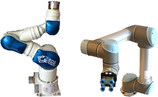
Figure 3. Left: Yaskawa SIA-20. Right: Universal robots UR5.
Download figure:
Standard image High-resolution imageTable 1. Robot specifications according to [11–14].
| Manufacturer | Model | Axes | Weight (kg) | Payload (kg) | Footprint (mm) | Accuracy ± (mm) | Horizontal reach (mm) | Vertical reach (mm) |
|---|---|---|---|---|---|---|---|---|
| Fanuc | M-20iA | 6 | 250 | 20 | 343 × 343 | 0.08 | 1811 | 2186 |
| KUKA | KR 20-3 | 6 | 254 | 20 | 154 × 204 | 0.05 | 1611 | 2026 |
| KR 16 arc HW | 6 | 145 | 16 | 566 × 566 | 0.04 | 1636 | 2051 | |
| Yaskawa | SIA 10 | 7 | 60 | 10 | 230 × 264 | 0.1 | 720 | 1080 |
| SIA 20 | 7 | 120 | 20 | 280 × 340 | 0.1 | 910 | 1320 | |
| Universal robots | UR5 | 6 | 18.4 | 5 | 150 × 150 | 0.1 | 850 | 850 |
| UR10 | 6 | 28.9 | 10 | 190 × 190 | 0.1 | 1300 | 1300 |
The UR10 has only a maximum payload of 10 kg but the small footprint and weight, in combination with the long reach, seem to qualify it for PIV. The laser illumination source weighs just over 10 kg, so that the UR10 cannot be used for holding the laser and only for moving the cameras. Since the camera set-up weighs less than 5 kg, the UR5 can be used instead.
The SIA-20 is a well established articulated robot known for its reliable performance in difficult cooperative scenarios, e.g. assembly of complex geometries. As a special feature, this robot has a seventh, redundant axis enabling the tool centre point (in this case laser or camera) to reach each 6D pose with numerous combinations of the seventh joint. This is essential if the robot is working in a confined space next to a wind tunnel.
2.3. Measurement of absolute accuracy
As mentioned above, the 'accuracy' provided by the data sheet, only refers to the uncertainty of the repeatability and not to the absolute accuracy which is of high importance for positioning laser and cameras. The aforementioned laser tracker [10] was used to check the absolute systematic uncertainty of the pose for both the SIA-20 and the UR5. The working distance of the laser tracker was around 2 m for the UR5 test and 4 m for the SIA-20, resulting in uncertainties for the reference of  m and
m and  m. Each robot was programmed to go to 20 different poses with an absolute distance between each pose of 50 mm. When the position was reached the movement was paused and the absolute position was measured. Afterwards the absolute distance of the TCP between each pose was calculated and compared to the theoretical displacement of 50 mm. Both the mean and standard deviation were calculated. During the measurements the UR5 was often not able to hold the pose precisely enough during the time needed to get a stable reading from the laser tracker. These points could not be evaluated quantitatively but they already give an indication of the ability of the robot to keep a stable pose. The standard deviation of the valid measurements is
  mm. Due to DIN EN ISO 9283 [9] the uncertainty needs to be specified with a confidence of 99% in an interval of three standard deviations around the average pose, resulting for the UR5 in an uncertainty of
  mm. When switching the servo motors off and applying the brakes, it was noticed that the pose of the UR5 strongly differs from the previously given pose. A separate measurement was performed to quantify this difference. Table 2 shows the displacement between the two different states. The standard deviation,
  mm, exceeds the given data from the manufacturer. The average movement of more than 4 mm when applying the brakes could be systematically corrected but the uncertainty of
  mm has to be considered when using this robot for PIV applications.
Table 2. UR5—Servo On/Off measurement.
| dX (mm) | dY (mm) | dZ (mm) | dAbs (mm) | |
|---|---|---|---|---|
| Servo on/off v1 | −1.80 | −1.68 | 3.66 | 4.41 |
| Servo on/off v2 | −1.81 | −1.73 | 3.72 | 4.48 |
| Servo on/off v3 | −1.84 | −1.88 | 3.88 | 4.69 |
| Servo on/off v4 | −1.96 | −1.98 | 4.08 | 4.94 |
| Average | −1.85 | −1.82 | 3.84 | 4.63 |
| Standard deviation | 0.07 | 0.14 | 0.19 | 0.24 |
The SIA-20 was generating a stable pose while the servo motors are switched on. The standard deviation for the repeated absolute positioning test was  mm resulting in a
  mm which is very close to the position repeatability given by the manufacturer. Due to the different method of applying the brakes when the servo motors are switched off, no change of its pose was measurable. The absolute accuracy showed an error of around 0.01% across its complete reach. When the robot reaches the end of its working space, the positioning error quickly increases to values over 200 μm. Therefore it is advised to avoid to use the robots in these positions. Based on these results, the Yaskawa SIA-20 was chosen to be a suitable robot arm for PIV measurements.
3. Integration in the wind tunnel
Restricted industrial environments, such as large scale wind tunnel facilities, have special demands in terms of safety regulations and additional external system integration. To enable fully automated PIV measurements, an embedded control framework is necessary. Communication to and from the integrated control system is done through a single interface to minimise control complexity, therefore eliminating possible error sources. Especially for wind tunnel applications, a real time communication is necessary in order to, for example, react to events related to the model motion system. The control unit of the SIA-20 supports a couple of communication possibilities, e.g. real time field bus protocols and binary GigE communication. This is another factor that should be considered when choosing the robot to use, since not all available system offer these possibilities.
Full integration into existing wind tunnel control systems (WTCS) is particularly useful for standardised test runs. Feedback loops enable two-way communication between the WTCS and the PIV system manager; see figure 4. A predefined measurement sequence can be automatically triggered whenever model and wind tunnel meet the desired flow conditions.

Figure 4. Communication between WTCS, PIV system and calibration database.
Download figure:
Standard image High-resolution imageThe PIV system manager is connected to all necessary hardware and software. Important status changes, such as 'flow condition reached' or 'data acquisition completed', are exchanged and adequately handled. In the same way, error handling enables early recognition of critical hardware failures. An example of a typical measurement sequence consists of following steps:
- (1)WTCS sends the requested measurement position the PIV system manager, e.g. X = 325, Y = −170, Z = 200, Yaw = 4, Pitch = 1.2, Roll = 0.
- (2)The system manager checks the calibration database for the closest calibrated position, e.g. X = 340, Y = −150, Z = 200, Yaw = 4, Pitch = 0, Roll = 0.
- (3)The position from the calibration database is modified to represent the requested position while keeping the relation between laser and cameras identical.
- (4)The robots move into position.
- (5)The system manager sets the focus and aperture for each camera based on the information in the calibration database. The scheimpflug angle [15] is also automatically set to avoid focusing problems caused by looking at an oblique angle to a plane. At the same time, the settings for the synchronizer are updated and the flashlamps and Q-Switches of the laser are switched on.
- (6)Typically di-ethyl-hexyl-sebacat (DEHS) seeding, generated by several groups of Laskin nozzles, with a particle distribution around 1 μm is used. The RoboPIV approach however, is independent of the preferred seeding type. The seeding density in the wind tunnel is continuously monitored by an optical sensor, in this example the ILA_5150 seeding sensor is used. If the seeding density drops below a predefined threshold, the particle generators are switched on automatically.
- (7)Once the PIV System is ready to measure, this is communicated to the WTCS.
- (8)When the WTCS confirms that wind tunnel and model are also ready to start the measurement, the laser starts firing and the images are acquired.
- (9)After all images are recorded, the WTCS is informed and the next measurement can be requested.
- (10)Simultaneously, the post processing is started on multiple processors. Once this is finished the result is sent to the WTCS for further analysis. When required, the data can be independently processed during image acquisition.
In combination with the simultaneously gathered wind tunnel data, the current run can be analysed in a quasi-online manner. The off-body flow characteristics can now also be used, together with force and pressure data, to optimise the measurement schedule accordingly. Automated movement into a secured parking position during run-down of the tunnel clears the space and enables direct access and safe working conditions for personnel inside the test section.
High-speed communication protocols, such as Fieldbus and EtherCat, are used to enable real-time communication between the WTCS and the RoboPIV system. The robots are able to follow the motion of the wind tunnel model, so new dynamic measuring possibilities are created. The complete sequence of measuring and processing the data is now done without the need of any human interaction. In this way the RoboPIV system provides high flexibility and can take measurements in a fully automated manner.
4. Measurement example
As an example the measurement of the wake behind the side view mirror of a full scale passenger car is used. The experiment was performed in a closed-loop wind tunnel with an open test section. Measurements were performed at freestream velocities between 20 m s−1 and 60 m s−1. The volume is composed out of nine independent, parallel measurement planes at 25 mm intervals. In this way a measurement volume of  mm3 is achieved. Each 2D/3C result is the average of 200 double images, acquired with 15 Hz. For these stereo PIV measurements, a Quantel evergreen laser with a maximum of 200 mJ per pulse was used. In combination with two ILA.PIV.sCMOS cameras providing 16-bit images with 5.5 Megapixels, only 140 mJ per pulse were required to obtain a sufficient signal to noise ratio and at the same time reducing reflections to a minimum. The pulse separation was set to 20 μs. Seeding was provided by two particle generators, each equipped with 40 Laskin nozzles. The DEHS particles had a typical size of 1 μm. The raw data was processed by using PIVView v3.6.5 and the ILA-Scheduler for parallel processing. The optical set-up resulted in a magnification factor of 4.5 px mm−1. In combination with a window interrogation size of
  px with a 50% overlap, this resulted in a spatial resolution of 5.3 mm/vector. For each camera the 200 images were averaged and subtracted from the raw data to reduce the influence of the car geometry in the background. Figure 5 shows the averaged velocity magnitude normalised by the freestream velocity. Due to confidentiality reasons, only the normalised velocity can be presented. For clarity in presenting the results, the X-axis has been stretched by a factor of 8. White areas represent regions where no valid data was obtained due to reflections. More information is available in the supplementary material (stacks.iop.org/MST/29/074009/mmedia).

Figure 5. Result of a car mirror wake flow (X-axis stretched by a factor of 8).
Download figure:
Standard image High-resolution imageSince 2D/3C measurements were performed the common accuracy and spatial resolution for this type of approach can be achieved. Although only nine parallel planes were measured to quantify the mirror wake, a cross-section can still be made; see figure 6. The slice has been made at Y = 200 mm and shows the contour of the normalised velocity magnitude together with the projection of the 3D vector field into the plane. If required, the spatial resolution in X can easily be improved by simply acquiring more planes e.g. at 10 mm or 5 mm intervals, which was not deemed necessary in this case.

Figure 6. Cross-section—Slice at constant Y.
Download figure:
Standard image High-resolution image
Regarding the measurement quality, a common major technical challenge in large industrial facilities is the rather large distance between camera and field of view (>5 m). Due to this, small deviations of camera and laser positioning scale accordingly into the raw image data. For planar stereo PIV measurements, the well-known disparity correction [15] can correct for this within a reasonable range. In combination with the precisely defined position of every system component, the resulting accuracy is similar to that of a common planar PIV setup without robotic arms.
By limiting the human interaction to the single task of starting the wind tunnel, the complete measurement of the shown volume, including processing the images in parallel on 20 processors, could be reduced to less than 30 min. In addition the same planes relative to the car can be measured by using the same calibration data, when the car is yawed to simulate cross-wind conditions. The time needed to perform a similar measurement without the use of robotics is strongly depending on the type of equipment used to partially automate the measurement. Without automation this type of measurement is not possible since the calibration process for each plane would already require around 4–5 h. Based on experience with partially automated systems [6], it is estimated that at least 1.5–2 h would be required to perform a similar measurement without the use of robotics.
5. Conclusion
RoboPIV systems have been proven to be valuable in an industrial environment. They offer the full flexibility of the available degrees of freedom while enhanced automation minimises the required wind tunnel time. The example measurement of a car mirror wake showed that the time required was at least reduced by a factor of 3. This becomes even higher when a measurement matrix only slightly differs in between points, for example multiple measurements at different cross-wind conditions. Since 2D/3C measurements were performed, the well-known stereo PIV algorithms can be used for processing the data. Therefore, the quality of the results, in terms of accuracy and spatial resolution, has not been compromised, while at the same time massively increasing the efficiency of the measurements.