


Abstract
We describe an all-angle negative refraction effect for surface acoustic waves in two-dimensional phononic crystals made of cylindrical pillars assembled in a square lattice and deposited on the surface of a semi-infinite substrate. The convexity of the iso-frequency contours of some branches leads to a negative refraction effect despite the fact that the effective index is not negative. It occurs for the frequency range where the group velocity is never in opposite direction to the phase velocity. In addition, the use of cylindrical pillars acting as acoustic resonant elements on the surface permits us to achieve this phenomenon with a sub-wavelength feature size structure; therefore, the effect of all-angle negative refraction can be shifted down to low frequencies, which is highly desirable for high-resolution superlensing applications. A flat lens for surface acoustic waves has also been designed. It demonstrates the focusing of an acoustic source into an image on the other side of the finite-size structure with an image resolution of (λ/4), which overcomes the Rayleigh diffraction limit. The numerical simulations are based on the efficient finite element method and analyze pillars and the substrate of lithium niobate.
Export citation and abstract BibTeX RIS

Content from this work may be used under the terms of the Creative Commons Attribution-NonCommercial-ShareAlike 3.0 licence. Any further distribution of this work must maintain attribution to the author(s) and the title of the work, journal citation and DOI.
1. Introduction
The propagation of acoustic and elastic waves in periodic structures with spatially modulated elastic moduli and mass density possesses a number of important properties such as the occurrence of frequency band gaps [1, 2]. In this case the transmission spectra exhibit a strong attenuation for which the acoustic or elastic waves are strictly prohibited in all propagating directions. The band gaps can first occur by using the Bragg interference of waves scattered by inclusions. Several authors reported band gaps for acoustic or elastic waves in two-dimensional (2D) and three-dimensional phononic crystals [3–5]. In addition, wave trapping and guiding or even demultiplexing [6–11] through discrete defects have also been reported. The second mechanism is based on locally resonant elements with a lattice constant several orders smaller than the relevant wavelength [12, 13]. In the case of surface acoustic waves, locally resonant band gaps for surface guided modes were demonstrated theoretically [14] and observed experimentally [15] in a square array of cylindrical pillars deposited on a semi-infinite substrate. The main advantage is that the local resonance can be altered by using shape design as in the case of Helmholtz resonators [16] and consequently tune the band gaps. Beyond the existence of the acoustic or elastic band gaps, there has been a great deal of interest in studying the wave propagating properties in these artificial crystals. In particular, these structures exhibit, under specific geometrical and composition conditions, unusual acoustic wave phenomena such as the negative refraction whereby the wave arrows are bending in the wrong way, which corresponds to an inverted Snell's law [17, 18]. These features allow considerable control over wave propagation and open the door to new approaches for a variety of applications such as design of superlenses that are suitable to overcome the diffraction limit and therefore to focus a point source theoretically into a perfect image [19] in the metamaterial regime. However, focusing a source through a photonic crystal leads to a diffraction-limited image [20]. Furthermore, in the case of phononic crystals, Sukhovich and co-workers demonstrated a sub-wavelength imaging of acoustic waves using a structure consisting of triangular lattice steel cylinders in methanol and all surrounded by water [21, 22].
Different kinds of negative refraction phenomena have been reported for electromagnetic waves [20, 23] and acoustic waves [21, 24–28]. One can obtain the negative refraction by using an effective medium showing a negative index related to the simultaneous negativity of permittivity and permeability for electromagnetic waves and the mass density and compressibility for acoustic waves [29]. This implies that waves (acoustic or electromagnetic) propagating in such media will have their Poynting vector and wave vector pointing in opposite directions. Another way of achieving the negative refraction is by using a periodic heterostructure where the effective index is controlled through the band structure. In this case, the physical constants are locally positive everywhere inside the crystal and negative refraction is achieved because of crystal anisotropy. Indeed, the band folding resulting from the periodicity can induce a negative slope above the first band exhibiting opposition between the group velocity and the phase velocity, which is an effect known as a backward wave [30, 31].
Finally, in the band diagram of some phononic crystal the negative refraction is not only achieved by employing a negative effective index or backward waves. Indeed, bands can have their iso-frequency contours convex near the M point of the Brillouin zone. This convexity leads to inward-pointing group velocities in the vicinity of M, while the group velocity and refractive index are both positive. Moreover, under a simple criterion, this negative refraction can occur for all the incident angles exhibiting an all-angle negative refraction (AANR), which is quite beneficial for superlensing applications.
In this paper, we report on the negative refraction of surface acoustic waves in pillar-based phononic crystals, occurring at the frequencies where both the group velocity and refractive index are positive. We consider a 2D phononic crystal consisting of cylinder pillars deposited on the surface of a semi-infinite medium, which have been studied experimentally and theoretically in [14, 15].
2. Formulation
The finite element method (FEM) is a numerical technique to solve partial differential equations (PDEs) and integral equations in the time domain as well as in the spectral domain. The FEM is a powerful method suitable for solving PDE over complicated domains, when the domain changes—e.g. for moving boundaries—and when the desired precision varies over the entire domain. In the literature, several authors have reported that phononic crystal devices with different geometries and compositions had been studied using FEM, in particular, when it is to calculate vibration band gaps [32] or to design cavities and waveguides—defect modes—in perfect structures.
The goal of the present study is to examine the case of cylindrical pillars arranged in a square lattice on top of a surface as depicted in figure 1. All form a monolith made of lithium niobate with an XY 128 cut. The mass density is ρ = 4628 kg m−3 and the three surface wave velocities are 3980, 3650 and 3818 m s−1 along the ΓX, ΓY and ΓM directions, respectively. The cylinder axis is parallel to the z-axis and perpendicular to the surface. The filling fraction is defined as F = πr2/a2, where a is the lattice parameter of the square array and r/a and h/a are, respectively, the relative radius and the relative height of the pillar.
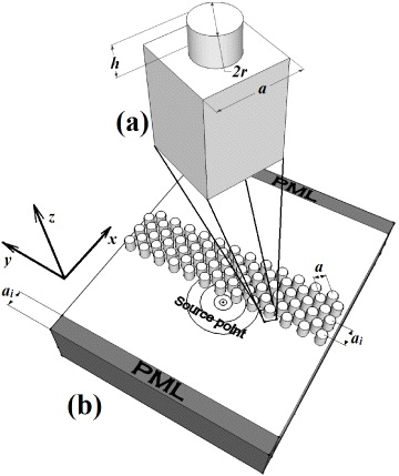
Figure 1. (a) Unit cell of pillar-based square array phononic crystals and (b) the model of a finite-size structure of the flat lens. The interface-parallel period  , where a is the lattice parameter of the square array of pillars.
Download figure:
Standard imageAccording to the Bloch–Floquet theorem, stress and deformation fields obey a periodicity law. Thereby, the mechanical displacements ui of the nodes on the boundary of the unit cell satisfy the following formula:

where (m,p) are the index of the unit cell and kx and ky are the components of the Bloch wave vectors in the x and y directions, respectively. With respect to the periodic boundary conditions above, the whole structure model has been reduced to an elementary unit cell depicted in figure 1(a), consisting of a single pillar deposited on the surface of a semi-infinite medium. The unit cell is meshed into unstructured small pieces (finite elements) connected by nodes in order to allow mechanical displacement (for elastic solids) and electrical potential (for piezoelectric solids) in the FE scheme.
In the case of monochromatic variation of mechanical and electrical fields with a time dependence ![$\exp [\mathrm {j}\omega t]$](https://content.cld.iop.org/journals/1367-2630/14/12/123030/revision1/nj447541ieqn2.gif) , where ω is the angular frequency, the general piezoelectric problem with no external applied force can be written as
, where ω is the angular frequency, the general piezoelectric problem with no external applied force can be written as

Here, Muu and Kuu are the mass and stiffness matrices of the purely elastic part of the formulation while the purely dielectric part is denoted by Kϕϕ. Kuϕ and Kϕu are piezoelectric coupling matrices. The vectors ϕ and u represent, respectively, the electrical potential and all displacements at the nodes of the mesh. As the angular frequency ω is a periodic function of the wave vector, the problem can be reduced to the first Brillouin zone. As a result, the degrees of freedom on the left edge can be related to the right one along the x direction (for instance), yielding the expression

where the wave vector kx varies in the interval (0,π/a) along the x direction. On the basis of this formula, we calculate the dispersion curves on the first Brillouin zone according to propagation directions. Therefore, we solve the eigenvalue problem to obtain the eigenfrequency solutions—angular pulsations ω. These solutions will then extend to the first Brillouin zone using symmetries.
Another model, illustrated in figure 1(b), is used to visualize negative refraction and the focusing of surface acoustic waves. It is a finite-size structure composed of a pillar array of 13a width and 6a thickness. With a specific polarization (ux,uz,uy), different shapes of the source (line, point) can be generated by applying an excitation on top of the surface at one or several nodes defining the shape of the source. To suppress reflections of the scattering wave from the edge, we apply a perfectly matched layer (PML) [33] on all sides of the simulation domain. The PMLs have the advantage of gradually absorbing the mechanical disturbances in the layers before they reach the outer boundaries. In this way, there will be no reflections that can disturb the propagation of the source wave. Indeed, we can write the governing equation which gives the stresses by Newton's second law as

where ρ is the density of the material. ux are the displacements and x are the coordinates. The parameter γj is an artificial damping at position xj in the PML. As the PML is added to attenuate the acoustic wave propagating in the plane (x,z) of the structure, only γx is different from 1 and is given by the expression

where xl is the coordinate at the interface between the regular domain and the PML and σx is a suitable constant. There is no damping outside the PMLs and here γx = 1. A suitable thickness of the PML as well as the value of σx must be found by calculations such that the mechanical disturbances are absorbed before reaching the outer boundaries. However, the absorption must also be sufficiently slow as reflections will occur at the interface between the regular domain and the PML if their material properties are not comparable. In our case, the width of the PML is equal to a in all domains and σx is fixed at 10−12, which ensures a very weak reflexion at the interfaces. The mechanical stresses Tjk depend on the strain as

where Cjklm are the elastic stiffness constants and the strain is related to the displacements as

These previous equations can be written as a PDE formulation and implemented in any free or commercial finite element software.
3. Results and discussion
In the concrete example, the pillars are arranged in a square lattice with two reduced heights h/a of 1 and 2. The reduced radius r/a is set to 0.4. These geometrical conditions make the pillars good candidates for local resonators to be used as building blocks of acoustic metamaterials. The band structure calculated along high-symmetry directions of the first irreducible Brillouin zone is plotted in figures 2(a) and (c) for h/a of 1 and 2, respectively. The thick black line represents the sound cone of the substrate. This limit is given by the smallest phase velocity in the substrate for all propagating directions. Basically, the resonant frequencies of pillars affect the surface-guided mode of the substrate. In particular, new surface modes appear in the non-radiative zone due to the interaction between the discrete vibration of pillars. Furthermore, locally resonant band gaps occur in the band diagram where no surface mode can propagate inside the periodic structure. As the reduced height of pillars increases from 1 to 2, we note that the branches shift to low frequency, leading to very large band gaps. Indeed, the arrays of pillars on a substrate behave in many ways as systems of springs and masses attached to a wall; then the longer the springs, the lower their resonant frequencies.

Figure 2. (a), (c) Band diagram of the out-of-plane polarization in the pillar-based phononic crystal made of lithium niobate, calculated along high-symmetry directions of the first irreducible Brillouin zone for pillar relative height h/a equal to 1 and 2, respectively. The color bar represents the normalized out-of-plane displacement U2z/(U2x + U2y + U2z). The z-axis is parallel to the pillars axis when the x- and y-axis define the plane of the periodicity. The relative radius is r/a = 0.4. The thick black line represents the sound cone of the substrate. This limit is given by the smallest phase velocity in the substrate for every propagation direction. (b), (d) The fourth branch frequency over all wave vector domains of the first Brillouin zone for pillar relative height h/a equal to 1 and 2, respectively. The color bar represents the frequency.
Download figure:
Standard imageMoreover, we have represented in figures 2(a) and (c) the out-of-plane polarization for all branches inside the non-radiative zone. These figures indicate that the fourth branch is mostly polarized in the z direction (parallel to the cylinders). We have selected this branch to explore the focusing effect, because it gives the possibility to transfer the acoustic energy through the crystal which is essential to achieve a negative refraction. The lower branches are mostly flat, indicating that the group velocity is very small, depicting a standing acoustic wave inside the phononic crystal. In figures 2(b) and (d), we have plotted the evolution of this branch in the interior of the first Brillouin zone (Γ–X–M–Y –Γ). The branch is covering with a positive slope a frequency range extending from 600/a to 1100/a (Hz) and from 200/a to 620/a (Hz) according to the two considered pillar heights. More precisely, we have calculated the group velocity (∂ω/∂k) along the high-symmetry directions of the Brillouin zone as shown in figure 3(a). We found that the group velocity is slowing down from the Γ point to reach a zero value in the X and M points. We also note that the group velocity is small along the XM direction, which is interesting for applications in ultra-refractive physics [34]. However, the group velocity always remains positive. The extended calculation of the group velocity of the fourth branch in the interior of the first Brillouin zone, shown in figure 3(b), confirms the observation that the group velocity of such a mode is positive in all wave vector domains.
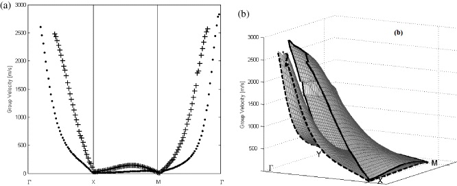
Figure 3. (a) The fourth branch group velocity ∂ω/∂k calculated along high-symmetry directions of the first irreducible Brillouin zone. Crossed and dotted curves were obtained for pillar relative height h/a equal to 1 and 2, respectively. (b) Extended group velocity calculation in all wave vector domains of the first Brillouin zone. The surfaces surrounded by solid and dashed blue correspond to pillar relative height h/a equal to 1 and 2, respectively.
Download figure:
Standard imageWe observe from figure 4 that in the ΓM direction the iso-frequency contours are convex in the vicinity of M having inward-pointing group velocities. Negative refraction can occur only over the lower frequency limit of fa = 1066 or 612 m s−1, according to the considered pillar heights (1 or 2), where the frequency contours start to become convex. It is well known that the refracted propagating modes are determined by the conservation of the frequency and the wave vector component parallel to the interface between the free surface and the pillar-based structure. If the surface normal is along the ΓM direction, and the contour is convex everywhere as illustrated for the reduced frequencies f1a = 1075 m s−1 (figure 4(a)) and f2a = 616 m s−1 (figure 4(b)), then an incoming plane wave from the free surface (i.e. without pillars) will couple to a single mode that propagates into this crystal on the negative side showing a negative refraction effect.

Figure 4. Several iso-frequency contours of the fourth branch of the pillar-based phononic crystal for pillar relative height h/a equal to 1 (a) and 2 (b). The black thick contour indicates the frequency lower limit with a convex shape. The blue line shows an example of an AANR at reduced frequencies of f1a = 1075 m s−1 (a) and f2a = 616 m s−1 (b). The dotted line represents the iso-frequency contour of an incoming wave from the free surface at the same frequencies (f1a and f2a).
Download figure:
Standard imageIn order to achieve an AANR for superlensing, the additional required condition is that the iso-frequency contour of the phononic crystal must be larger than the iso-frequency contours for the free surface. In such a case, all incoming wave vectors are included within the iso-frequency contour of the phononic crystal. Therefore, we have inserted in figure 4(a) a dotted circle representing the iso-frequency of the free surface medium at the reduced frequencies f1a and f2a. Consequently, at these frequencies we meet the conditions to obtain an AANR in the pillar-based structure. It is clear from this example that the selected mode has ∂ω/∂k ⩾ 0 everywhere within the first Brillouin zone, meaning that the group velocity is never in opposite direction to the phase velocity. In this sense, our phononic crystal is acting as a uniform medium with a positive effective index. Based on these conditions, we have evaluated the fractional frequency range of 1.5% around f1 and 1.3% around f2 where the AANR will occur.
Besides, there is a supplementary condition on the frequency to avoid diffraction and to obtain a single-beam behavior. In fact, the acoustic source must operate with reduced frequency fa lower than (0.5Csa/ai), where Cs is the surface wave velocity and ai is the interface-parallel period between the free surface and the pillar-based structure and is equal to ( ). In our case, this condition is obviously met since the branches in the band diagram are resulting from the interaction of acoustic resonances of the cylindrical pillars. Consequently, they can be shifted down to low frequencies by just increasing the height of the pillars while the array period of the crystal remains unchanged. The advantage of such a pillar-based structure will permit us to avoid the diffraction and achieve this phenomenon with sub-wavelength feature size structure which is highly desirable for high-resolution superlensing applications.
The main advantage of such an AANR is the possibility of designing a flat lens that can focus a point source onto an image on the other side of the lens. To study the focusing properties of the lens for the surface acoustic wave, we built a finite sized pillar-based structure with a width of 13ai and a thickness of six layers. A point source is placed close to the left side of the flat lens and is operating, according to the considered pillar heights (1 or 2), at the reduced frequencies f1a = 1075 m s−1 (figure 5(a)) or f2a = 616 m s−1 (figure 5(c)). The frequency of the incident wave is chosen where AANR may occur. Practically, an out-of-plane excitation is applied on one node of the meshing at 5.55a in the X direction and at 6.55a in the Y direction. It is important to note that the width of the point source is smaller than the wavelength of the surface at the operating frequency, making it suitable for the investigation of the super-resolution properties of the flat lens. In figure 5, we plot the field pattern of the out-of-plane displacement of the emitting wave and their images across the finite-size structure. We observe a high-quality image formed in the opposite side of the finite size of the structure. To evaluate the image resolution, figures 5(b) and (d) show a section of the magnitude of the displacement in the y direction at the maximum value of the displacement in the x direction. The ultimate resolution limit of a conventional imaging system is given by half of the spot wavelength λ/2 [21]. The effective resolution Δ/2 is evaluated by fitting at the point image the central lobe of the out-of-plane displacement with the sinc(2πx/Δ) function as illustrated in figures 5(b) and (d). The latter shows that one gets peak widths of 2.39a and 3.06a for pillar-reduced heights of 1 and 2, respectively. Considering the selected frequencies f1a = 1075 m s−1 and f2a = 616 m s−1 for these two pillar heights and the free surface wave velocity Cr = 3818 m s−1 along the ΓM direction, this corresponds to an effective resolution of Δ/2 = 0.34λ and 0.25λ, respectively. These resolutions are smaller than the diffraction limit λ/2 by a factor of up to 2 giving strong evidence for a sub-wavelength imaging with the surface acoustic wave.
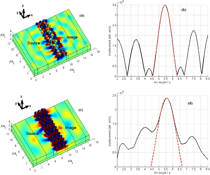
Figure 5. (a), (c) Out-of-plane displacement field of a point source and its image across a pillar-based phononic crystal flat lens. Dimensions are given according to the interface-parallel period ( ). The point source operates at f1a = 1075 m s−1 and f2a = 616 m s−1 for pillar relative height h/a equal to 1 (a), (b) and 2 (c), (d), respectively. The x-axis of figures (a) and (c) corresponds to the ΓM wave propagating direction on the surface of the phonic crystal unit cell. Blue, green and red correspond to negative, zero and positive displacement, respectively. (b), (d) Section of the out-of-plane magnitude of the displacement along the direction parallel to the lens interface. The x position of these sections corresponds to the maximum value of the displacement along the direction perpendicular to the lens interface. The data fit to a sinc function (dashed red line) gives a half-width of the primary peak,
  , of 0.34λ (a), (b) and 0.25λ (c), (d).
Download figure:
Standard imageFurthermore, we could note in figure 5(c) an intense out-of-plane displacement field inside the phononic structure where all pillars are vibrating with maximum magnitude. Thus, the mechanism by which this phenomenon occurs could be attributed to amplification of evanescent modes through the bound interface or slab modes of the pillar-based structure. These modes propagate only in the direction parallel to the free surface–pillars interface. The ability of the source to excite bound modes is an important parameter in this mechanism. For instance, the distance between the source and the lens is a critical condition as the source has to excite these evanescent waves which contribute to the reconstruction of the image.
4. Conclusion
In summary, we have demonstrated an AANR effect for surface acoustic waves in 2D phononic crystals made of cylindrical pillars assembled in a square lattice and deposited on the surface of a semi-infinite substrate. Based on the efficient FEM, the iso-frequency contour estimations showed the hallmark of the negative refraction effect without resorting to a negative effective index. Indeed, we obtained the negative refraction in a frequency range where the group velocity is never the opposite of the phase velocity. With respect to defined criteria, an AANR effect is highlighted in some frequency range. Thus, considering all incident angles, acoustic waves will be refracted in the opposite direction, ensuring the condition of focusing a point source is achieved. In addition, the use of cylindrical pillars acting as acoustic resonant elements on the surface permits us to achieve this phenomenon with a sub-wavelength feature size structure, overcoming the Rayleigh diffraction limit. This pillar-based structure could be a potential candidate to show other wave phenomena such as the super-prism effect or acoustic cloaking.