This paper proposes the analysis of the tolerances (values, types, datum) and their effects on a mechanical assembly, as a high-performance car engine, by means of a Computer-Aided Tolerancing software. The 3D tolerance stack-ups are investigated to assess the fulfillment of the functional requirements as well as the performance specifications of the assembly. Moreover, after identifying the tolerances that mainly affect the product variability, we finally propose some corrective actions on the tolerances and assess their functional allocation, tightening or relaxing their values, ensuring assemblability and cost reduction.
1 Introduction
In the global marketplace, the search for a perfect balance between performance fulfillment and economic feasibility is mandatory. Therefore, the assembly optimization as well as the reduction of the variation of the key dimensions of parts are primary goals to guarantee the product quality with cost and time savings. The application of geometric dimensioning and tolerancing (GD&T) specifications to a product still represents a typical industrial issue [1]. The difficulties in the definition of the correct GD&T scheme and in the tolerance allocation choice are due to the complexity of the real industrial cases, in which different requirements of product life cycle phases must be considered [2, 3]. Usually, the choice of the Datum Reference Frame (DRF) and of the tolerance specifications derives from previous experience and background trial and error tests, whose effectiveness is not always guaranteed. The literature presents some useful references, even if sometimes they are difficult to link with the real application. Thanks to advanced simulation such as Computer-Aided Tolerancing (CAT) software, the tolerance analysis approach improves the knowledge about the process and enables the optimization of the GD&T scheme and the assembly process. These tools represent a support during the early design phases to validate the product tolerance design. For industrial fields as automotive, the product optimization through CAT simulation can produce a consistent increase of quality levels and a reduction of unnecessary costs [4, 5]. For these reasons, this work aims at performing the tolerance analysis of an automotive assembly, suggesting corrective actions on the tolerance values and allocation schemes. A high-performance engine assembly is selected as a case study for its complexity and representativeness among industrial applications.
The final goal is to identify a set of general allocation schemes of typical industrial cases to be used as guidelines for the GD&T definition and for the selection of tolerances, considering the specific functional requirements of each application.
Advertisement
2 Method
To reach the expected levels of customer’s satisfaction, quality has become a design approach based on a group of procedures, first the Tolerance Design process. Tolerance Design process is mainly performed by CAT-based approach, which is integrated in the early design phases [6]. The general workflow has an input phase of preparation and setting-up, a modelling and simulation phase and the final output analysis and synthesis phase [6, 7], with their subphases here reported:
Preparation: Data collection, CAD models import in the CAT software, identification of parts geometry, elimination of non-contributing parts.
Functional analysis: Functional and technological requirements definition, identification of the measurements consistent with the targets, identification of the functional features of the parts and Datum Reference Frames (DRFs).
Assembly sequence definition: Relative positioning, clamping and fixing operations of the parts.
Tolerance set-up: Identification of the dimensional and geometrical tolerances (GD&T) on the parts, definition of the tolerance values.
Measurements set-up (i.e. stack-up analysis responses to be controlled).
Analysis and results: Simulation run and data analysis with the target values.
Synthesis: If necessary, optimization of tolerance values and types, final verification of the requirements.
3 Case Study: V12 Engine Assembly
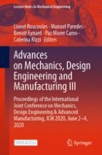
We selected a high-performance V12 engine assembly as a case study, performing a tolerance analysis to verify the effectiveness of its assembly operations. We focused on the bolting operations between the upper (UC) and lower crankcase (LC), and between the cylinder heads and the UC (Fig. 1).
Fig. 1.
V12 engine assembly: 1. UC, 2. LC bushings, 3. LC studs, 4. LC, 5. Cylinder head bushings, 6. Head gasket, 7. Cylinder head studs, 8. Cylinder head.
×
These operations are crucial during the assembly phases since they affect the performance and reliability of the engine itself. To fulfil the design requirements, we performed the 3D tolerance analysis of the engine assembly, then we assessed the adopted GD&T and tolerance allocation schemes, and the tolerance values.
The CAT software adopted is Cetol 6σ (Sigmetrix®), an add-in workbench integrated in CATIA V5 (Dassault Systemes®) platform, based on a vector loop approach [8]. The components to be simulated are treated as rigid models, without parts distortion. After the simulation, the statistical and the sensitivity analysis of the tolerances permit to identify the main contributors to variation.
Advertisement
In accordance with the proposed method, the following steps are performed.
Preparation and Setting Up: The CAT model includes the following main components: the UC, the LC, the head gasket and the cylinder heads, as well as the fixture elements, i.e. the crankcase bushings and the studs. There are 14 bushings and 28 studs on the LC side, and 2 bushing and 14 studs on the cylinder heads side. Since they achieve the positioning and bolting operations of the assembly, their interface with the other components is crucial. Non-contributing parts as the head gasket and one of the cylinder heads were not considered in the simulation.
The assembly sequence is identified: the UC is fixed (i.e. it is held in position by an external fixturing system), the bushings are inserted in their housings on the UC with interference fit, then the studs are inserted in their housings on the UC. Once these components are positioned, the LC and the cylinder heads are inserted. The bolting operations on the studs complete the assembly of the engine.
Modelling and Simulation: With respect to this assembly sequence, the Datum Reference Frames (DRFs) for the components (Fig. 2) are analysed.
Fig. 2.
Datum Reference Frame (DRF) identification on the UC.
Starting from the UC, the first reference A is the surface between the parts. Then, the holes corresponding to the two opposed external bushings are defined as references B and C. Finally, a position tolerance with respect to A, B, C locates the other housings of both bushings and studs. All the tolerances are transferred from the technical drawings to the 3D models, with respect to the DRF.
As functional measures, we set the gaps of both bushings and studs with respect to their housings in the engine components. We checked the absence of physical interferences between the parts (gap < 0), assessing a target value of ±3σ.
Analysis and Synthesis: The analysis of the simulation outputs provides the following results. We divided them in two groups: (A) the gap measurements between bushings and their housings, and (B) the gap measurements between studs and their housings, for both the UC-LC (1) and the UC-cylinder heads sides (2):
A.1 The target condition is not verified, with an average value of ±1.95σ (Fig. 3). The sensitive analysis identifies the main contributors of variation, the position tolerance of the bushing housings on both the UC and the LC.
A.2 The target condition is not verified, with an average value of ±1σ. The sensitive analysis identifies the main contributors of variation, the position and dimensional tolerance of the bushing housings on the cylinder head.
Fig. 3.
Simulation outputs of A.1 measurements, with main contributors to variation.
×
B.1 The target condition is completely verified, with a large safety margin, and an average value of ±4.63σ (Fig. 4). The main contributors of variation are the position tolerance of the stud threaded seats and of the stud housings on the LC.
B.2 The target condition is verified, with a lower safety margin compared to B.1, with an average value of ±3.5σ, near the limit of acceptance. The main contributors of variation are the position tolerance of the stud threaded seats and the dimensional tolerance of the stud housings on the cylinder head.
Fig. 4.
Simulation outputs of B.1 measurements, with main contributors to variation.
×
The outputs analysis leads to the following corrective actions (Tables 1 and 2).
Table 1.
Tolerance values of the main contributors need to be tightened (A.1 and A.2)
Tolerance
Original value
Corrected value
A.1
Position tolerance of bushing housings on the UC and LC
0.03
0 with M.M.C.
Dimensional tolerance of bushing housings on the LC
F7
E7
A.2
Dimensional tolerance of bushing housings on the UC
K6
P6
Dimensional tolerance of external diameter of the bushings
+0.025 +0.012
js8
Dimensional tolerance of bushing housings on cylinder heads
H7
E6
Position tolerance of bushing housings on cylinder heads
0.05
0.03
Table 2.
Tolerance values of the main contributors are relaxed (B.1 and B.2)
Tolerance
Original value
Corrected value
B.1 and B.2
Concentricity tolerance of studs
0.1
0.3
Position tolerance of stud housings on the LC
0.2
0.6 with MMC
Dimensional tolerance of stud housings on the LC
+0.1 −0.05
+0.2 −0.1
Dimensional tolerance of stud threaded seats on the LC
0.2
0.2 with MMC
Position tolerance of stud housings on the cylinder head
0.4
0.4 with MMC
After these corrective actions, the simulation shows the fulfillment of the functional targets for both the bushings and the studs. This result is also due to the introduction of the maximum material condition (MMC) and the relaxation of the tolerance ranges for the stud-related tolerances.
×
4 Discussion and Conclusions
The comparison between the resulting measurement ranges and the functional targets identifies two different scenarios. The outputs of A.1 and A.2 show a reduced capability of the engine assembly process compared to the target of ±3σ, therefore we tight the tolerance ranges of the main contributors to variation to improve the assembly performance. On the other hand, B.1 and B.2 show that the values of the stud-related tolerances are too tight, so it is possible to relax the tolerance values of the main contributors to variation, reducing the manufacturing cost of parts, and reaching the expected production target. Thanks to CAT simulation, the tolerance design of the assembly is checked and validated, providing corrective actions. Thanks to the sensitivity analysis, the most influencing tolerances and reference elements are identified, with respect to the functional requirements of the case study. These outputs will be useful for future works, to extract guidelines for the GD&T definition and for the allocation of tolerances in similar applications, developing an archetype for industrial cases of bolt assembly.
Open Access This chapter is licensed under the terms of the Creative Commons Attribution 4.0 International License (http://creativecommons.org/licenses/by/4.0/), which permits use, sharing, adaptation, distribution and reproduction in any medium or format, as long as you give appropriate credit to the original author(s) and the source, provide a link to the Creative Commons license and indicate if changes were made.
The images or other third party material in this chapter are included in the chapter's Creative Commons license, unless indicated otherwise in a credit line to the material. If material is not included in the chapter's Creative Commons license and your intended use is not permitted by statutory regulation or exceeds the permitted use, you will need to obtain permission directly from the copyright holder.